engine control system BMW 528i 1998 E39 Workshop Manual
[x] Cancel search | Manufacturer: BMW, Model Year: 1998, Model line: 528i, Model: BMW 528i 1998 E39Pages: 1002
Page 4 of 1002
Downloaded from www.Manualslib.com manuals search engine
Selected Boolcs and Repair Information from Bentley Publishers
MINI Cooper
MINI Cooper Service Manual: 2002-2004 Bc,illc!! Pirl~lisl!~~ ISBN 0-8376-1068-0 AlexZanardi - My Swectest Victory rllex Zmmrdi itjill! Ginrz11,cn Gns~x~ri,,i ISBN (1-8376-1249-7
BMW 3 Series IE36) Scrvire Manual: 1992-1998,318ilisliC. 323is/iC, 3?5i/is/iC, 328ilisliC, M3 Be~iili.!~ Pirl?lisliers ISBN 0-8376-0326-9
BMW
5 Series Scrvicc Manual: 1997-2002 525i, 528i. 530i. 540i, Sedan, Sport Wagon Bcrrlluy P~rlilishens ISBN 0-8376-0317-X
Porsclze Tl~c Unfair Advantage hlirrk Do,~ult,re ISBN 0-8376-0073-Iilrcj; Porsche: Excellcncc Was Expected I
Porschc 911 Enthusiast's CompanionT3' Aiirinri Slr~,tzlli~~r ISBN 0-8376-0293-9
BMW 6 Scries Enthusiasl's CompanionTh1 Jc~.li'iil!/ liV0l10li ISBN 0-8376-0193-2 Driving Tlw Skip Bizl.bul- Riicing Sclaiol ISBN 0-8376-0227-0
BMW 7 Series Servicc Manual:1988-1994, 735i,735iL, 74%. 740iL. 750iL Beritlc!/ I'irblislrens ISBN 0-8376-0328-5
A French I
Bosch 1-landbook for Automotive Elcctrics and Elcchonics Rillrcr I Bwcli, GrjilrH ISBN 0-8376-1050-8
Bosch Handbook for Diesel-Engine Managcmcnt Ril1iei.t Bosdl, ClrrbH ISBN 0-8376-1051-6
Bosch Handbook for
Gasolinc-Engine Management Robcrf Bosclr, G~ribH ISBN 0-8376-1052-4
'7
Battle for lhe Bcelle I
Jells, Golf, GTI Scrvicc Manual: 1999-2005 1.8L lurbo, 1.9LTDI diesel, PD dicscl, 2.0L ga5aline. 2.81 VRG B~.!iIlcy Pt,blislicrs ISBN 0-8376-125-9
New Bcctle ServiceManual:1998-20021.8L turbo, 1.91 TDI diesel, 2.0L gasoline Bailicy P~irirlishers ISBN 0-8376-0376-5
New Bcctle 1998-2005, New Beetle Convcrtible2003-2005 Official Factory
Rcpair Manual an CD-ROM
I~olkiatgurr ~JAriicricn ISBN 9784-8376-1265-2
Boscll Fuel Injection and Enginc Management Clml-Its 0. Pmbsi, SAE ISBN 0-8376-0300-5 Clzevrolet
Corvctlc Illustralcd Encyclopedia Torn Beifurli ISBN 0-8376-0928-3
Racc Car Aerodynamics losupli Kntz ISBN 0-8376-014>8
Road &Track Illustrated Automotive
Dictionary
Joltri Dilrkl ISBN 0-8376-11143-6
Scientific Design of Exl~aust and Intake Systems I'lrililr H. S,sillr 0-8376-0309-9 Corvette Fuel
Injection &Electronic Enginc Managcment 1982-2001: Clmrlcs 0. I1rol,sl, SAE ISBN 0-8376-0861-9
I'acrat Ser\,irc hl.>nu.~l: 1998-2004.1.81. lurbu, 2.RL Vb, .l.IIL \\'8, inrludinl: tv.~gc>n and 4blOTION Giiitlc!/ P~iiblislicrs ISBN 0-8376-0360-2 Zora Arkus-Duntov:Thc Lcgcnd Behind corvt.ttc Je1.q Birl-1011 ISBN 0-8376-0858-9
Ci~evmlcl by the Numbers 1965-1969: The
Essential Chcvrolct Paris Refcrcncc illn,i Cnl2i11 ISBN 0-8376-0956-9
Passat. Passat Waron 1998-2005 Official
Gnlf,
GTI, Jctta 1993-1999, Cabrio 199% 2002 Official Factory Repair Manual on
CD-ROM
Volhsiraigu>t oJA,rtrricn ISBN 978-0-8376-1263-8
Jetta, Golf, GTI: 1993-1999,
Cabtio: 1995- 2002 Scrvicc Manual ll~iillcy I'trblisln.~~~ ISBN 0-8376-0366-8
Alfa Romco All-Alloy Twin Cam
Companion 195G1994 1'nl Bncdulr ISBN 0-8376.0275-0
Alfa Romco Owner's Bibl~'~' 1'1~1 Bmrlul! ISBN 0-8376-0707-8
Ford
Ford Fuel Injection and Electronic Engine
Control: 1988-1993
Clinrlcs 0. Pmirsl, SrlE ISBN 0-8376-03Lll-3 Arldi
Audi A4 Repair Manual: 1996-2001.1.8L lurbo, 2.8L. including Avant and quatlro Buirile!/ Ptrhlislters ISBN 0-8376-0371-.I
EuroVan Official Factory Rcp.,ir Manual:
1992-1999
I/~llhio~sar, ifAii!wicn ISBN 0-8376-0335-8
Tbc Official Ford Mustang 5.0 Technical
Reference & I'crformancc Handbook:
1979-1993
A1 l
1998-2004, Avant 1999- 2004, allroad quallro 2001-2005, 56 Avant 2002-2004, RS6 2003-2004 Official
Factory Rcpair Manual on CD-ROM
Ai!dioJ/in,er.ini ISBN 978-0-8376-1257-7
Jccp CJ Rubuildcr's Manual: 1972-1986 MOSI~S Lltii~l ISBN 0-8376-0151-7
Jccp Owner's Biblen', Third Edition Moscs Lzrdel ISBN 0-8376-1117-2 Automotive Reference
Bcnlluy Publishers has published iewicc manualsand autornohilcboolissinrc 1950. Plcasc write to us at 1734 Mniincliusctts Ave..Cnmbridge, kIA02138,i~isit ourivcb sitc, ol-c,lll 1-800-12345'15 ini a free copy ofnurcolaiog.
BMW
BMW 23 Sarvicc Manual: 1996-2002. including 23 Roadster, 23 Coupe, M
Roadster, M Coupe
Be~illq Pi,blislicis ISBN 0-8376-1250-0
BMW 3 Scrics (Ed61 Scrvicc Manual:
Mcrcedes-Bcnz Technical C~mpanion'~~' Bu,rllu!! P,rlilislio.i ISBN 11-8376-1033-8
Mcrccdcs-Bcnz E-Class (W124) O~vner's BibleT>' : 1986-1995 llu~tilc!~ Pi~lriisiieis ISBN 11-8376-0230-(1
Urlilii-!~ P~~Blisi~~rs ISBN 11-8376-11772
Page 5 of 1002
Downloaded from www.Manualslib.com manuals search engine
Foreword
For the BMW owner with basic mechanical skills and for independent auto service professionals.
this manual includes many of the specifications and procedures that were available to an
authorized BMW dealer service deoartment as this manual went to
Dress. The BMW owner with , no intention of working on his or her car will find that owning and referring to this manual makes it
possible to be better informed and to more
Itnowledgeably discuss repairs with a professional
automotive technician.
If you are a BMW owner intending to do maintenance and repair work, make sure you have
screwdrivers, a set of metric wrenches and sockets and metric Allen and
Torx wrenches, since
these basic hand tools are needed for most of the work described in
this manual. Many procedures
also require a torque wrench to ensure that fasteners are tightened properly and in accordance
with specifications. Additional information on basic tools and other tips are in
010 General. In
some cases, the text refers to special tools that are recommended or required to accomplish
adjustments or repairs. These tools are usually identified by their
BMW special tool number and
illustrated.
Disclaimer
We have endeavored to ensure the accuracy of the information in this manual. When the vast
array of data presented in the manual is
talten into account, however, no claim to infallibility can
be made. We therefore cannot be responsible for the result of any errors that may have crept into
the text. Please also read the Important Safety Notice on the copyright page at the beginning of
this book.
Prior to starting a repair procedure, read the procedure,
001 General Warnings and Cautions
and the warnigns and cautions that accompany the procedure. Reading a procedure before
beginning
work will help you determine in advance the need for specific skills, identify hazards,
prepare for appropriate capture and handling of hazardous materials, and the need for particular
tools and replacement parts such as gasltets.
Bentley Publishers encourages comments from the readers of this manual with regard to errors,
and/or suggestions for improvement of our product. These communications have been and will be
carefully considered in the preparation of this and other manuals. If you identify inconsistencies in
the manual, you may have found an error. Please contact the publisher and we will endeavor to
post applicable corrections on our
website. Posted corrections (errata) should be reviewed before
beginning
worlc. Please see the following web address:
BMW offers extensive warranties, especially on components of the fuel delivery and emission
control systems. Therefore, before deciding to repair a BMW that may be covered wholly or in part
by any warranties issued by
BMW of North America, LLC, consult your authorized BMW dealer.
You may find that the dealer can
make the repair either free or at minimum cost. Regardless of its
age, or whether it is under warranty, your BMW
Is both an easy car to service and an easy car to
get serviced. So
if at any time a repair is needed that you feel is too difficult to do yourself, a trained
BMW technician is ready to do the job for you.
Bentley Publishers
Page 8 of 1002
Downloaded from www.Manualslib.com manuals search engine
I General Warnings and Cautions
WARNINGS (continued)
. The air conditioning system is filled with chemical refrigerant,
which is hazardous. The AIC system should be serviced only by
trained technicians using approved refrigerant recoverylrecycling
equipment, trained in related safety precautions, and familiar with
regulations governing the discharging and disposal of automotive
chemical refrigerants.
. Do not expose any part of the AIC system to high temperatures
such as open flame. Excessive heat will increase system pres-
sure and may cause the system to burst.
Some aerosol tire inflators are highly flammable. Be extremely
cautious when repairing a tire that may have been inflated using
an aerosol tire inflator. Keep sparks, open flame or other sources
of ignition away
from the tire repair area. Inflate and deflate the
tire at least four
times before breaking the bead from the rim.
Completely remove the tire from the rim before attempting any re-
pair.
Cars covered by this manual are equipped with a supplemental
restraint system (SRS), that automatically deploys
airbags and
pyrotechnic seat belt tensioners
In the event oi a frontal or side
impact. These are explosive devices. Handled improperly or with-
out adequate safeguards, they can be accidently activated and
cause serious injury.
- The ignition system produces high voltages that can be fatal.
Avoid contact with exposed terminals and use extreme care when
working on a car with the engine running or the ignition switched
on.
. Place jack stands only at locations specified by the manufacturer.
The vehicle
illtino iack su~olied with the vehicle is intended fortire -. , . changes only. A heavy duty floor jack should be used lo lift vehicle
before installing
jacl( stands. See 010 General.
- Battery acid (electrolyte) can cause severe burns. Flush contact
area
with water, seek medical attention.
Aerosol cleaners and solvents may contain hazardous or deadly
vapors and are highly flammable. Use only in a well ventilated ar-
ea. Do not use on hot surfaces (engines, brakes, etc.).
Do not remove
coolant reservoir or radiator cap with the engine
hot. Danger of burns and engine damage.
CAUTIONS-
See also WARNINGS
- if you lack the slqills, tools and equipment, or a suitable worl(shop
for any procedure described in this manual, leave such repairs to
an authorized BMW dealer or other qualified shop.
BMW is constantly improving its cars and sometimes these
changes, both in parts and specifications, are made applicable to
earlier models. Therefore, part numbers listed in this manual are
for reference only. Always check with your authorized BMW deal-
er parts department for the latest information.
Before starting a job, make certain that you have all the neces-
sary tools and parts on hand. Read ail the instructions thorough-
ly, and do not attempt shortcuts. Use tools appropriate to the
work and use only replacement parts meeting BMW specifica-
tions.
Use pneumatic and electric tools only to loosen threaded parts
and fasteners. Never use these tools to tighten fasteners, espe-
cially on light alloy parts. Always use a torque wrench to tighten
fasteners to the tightening torque specification listed.
Be mindful of the environment and ecology. Before you drain the
crankcase, find out the proper way to dispose of the
oil. Do not
pour
oil onto the ground, down a drain, or into a stream, pond or
lake. Dispose of waste in accordance with Federal, State and
Local laws.
The control module for the anti-lock brake system
(ABS) cannot
withstand temperatures from a paint-drying booth or a heat
lamp
in excess of 203" F (95°C) and should not be subjected to tem-
peratures in excess of 185°F
(8S°C) for more than two hours.
- Before doing any electrical welding on cars equipped with ABS,
disconnect the battery negative
(-) terminal (ground strap) and
the ABS control module connector.
- Always make sure ignition is off before disconnecting battery.
Label battery cables before disconnecting. On some models, bat-
tery cables are not color coded.
Disconnecting the battery may erase fault code@) stored in control
module memory. Using special BMW diagnoslic equipment, check
lor
iauit codes prior to disconnecting the battery cables. If the mal-
I.mct on ndicator Ignt (MIL) s I. ..minaled. see OBD On-Board
Diaanostics
Tl11s iant is iuenlfted as lne Check Ena~ne oht
(1997-2000 models jor~ervlce Engine Soon light (2061 andlater
models). If any other system iaults have been detected (indicated
by an illuminated warning light), see an authorized BMW dealer.
If a normal
or rapid charger is used to charge battery, the battery
must be disconnected and removed from the vehicle in order to
avoid damaging the vehicle.
- Do not quick-charge the battery (for boost starting) for longer
than one minute. Wait at least one minute before boosting the
battery a second time.
* Connect and disconnect a battery charger only with the battery
charger switched off.
- Sealed or "maintenance free" batteries should be slow-charged
only, at an amperage rate that is approximately 10% of the bat-
tery's ampere-hour (Ah)
rating.
. Do not allow battery charging voltage to exceed 16.5 volts. If the
battery begins producing gas or boiling violently, reduce the
charging rate.
Boosting a sulfated battery at a high charging rate
can cause an explosion.
Page 35 of 1002
Downloaded from www.Manualslib.com manuals search engine
Maintenance
Service Interval lndicator (Sll)
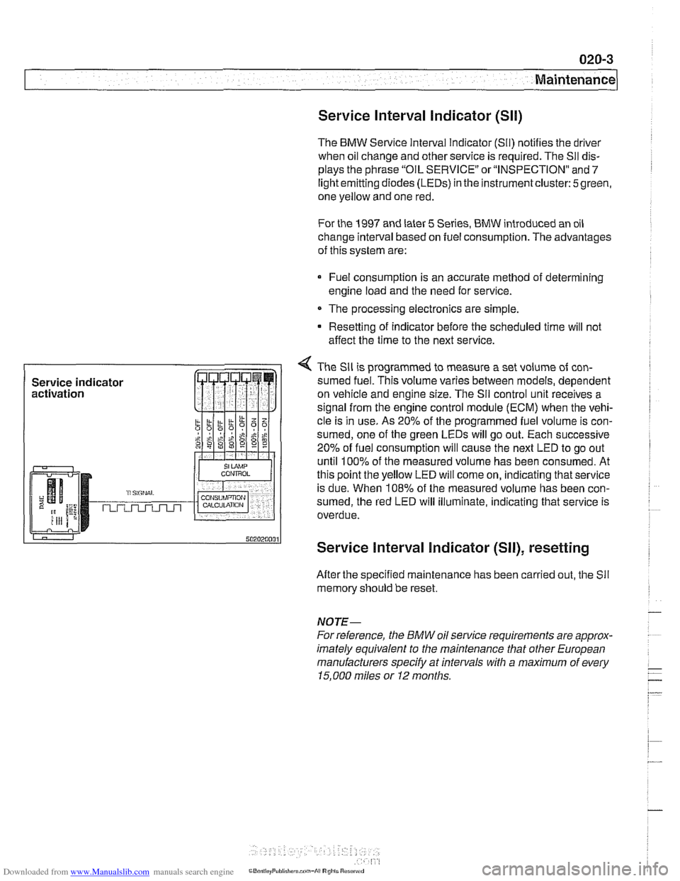
The BMW Service Interval lndicator (SII) notifies the driver
when oil change and other service is required. The
Sll dis-
plays the phrase "OIL SERVICE"
or"INSPECTI0N" and 7
light emitting diodes (LEDs) in the Instrumentcluster: 5green,
one yellow and one red.
For the
1997 and later 5 Series, BMW introduced an oil
change interval based on fuel consumption. The advantages
of this system are:
Fuel consumption is an accurate method of determining
engine load and the need for service.
The processing electronics are simple.
Resetting of indicator before the scheduled time will not
affect the time to the next service.
4 The Sll is programmed to measure a set volume of con-
sumed fuel. This volume varies between models, dependent
on vehicle and engine size. The
Sil control unit receives a
signal from the engine control module (ECM) when the vehi-
cle is in use. As
20% of the programmed fuel volume is con-
sumed, one of the green LEDs will go out. Each successive
20% of fuel consumption will cause the next LED to go out
until
100% of the measured volume has been consumed. At
this point the yellow LED will come on, indicating that service
is due. When
108% of the measured volume has been con-
sumed, the red LED will illuminate, indicating that service is
overdue.
Service Interval Indicator (SII), resetting
After the specified maintenance has been carried out, the Sll
memory should be reset.
NOTE-
For reference, the BMW oil service requirements are approx-
imately equivalent to the maintenance tliat other European
manufacturers specify at intervals with a maximum of every
15.000 miles or I2 months.
Page 39 of 1002
Downloaded from www.Manualslib.com manuals search engine
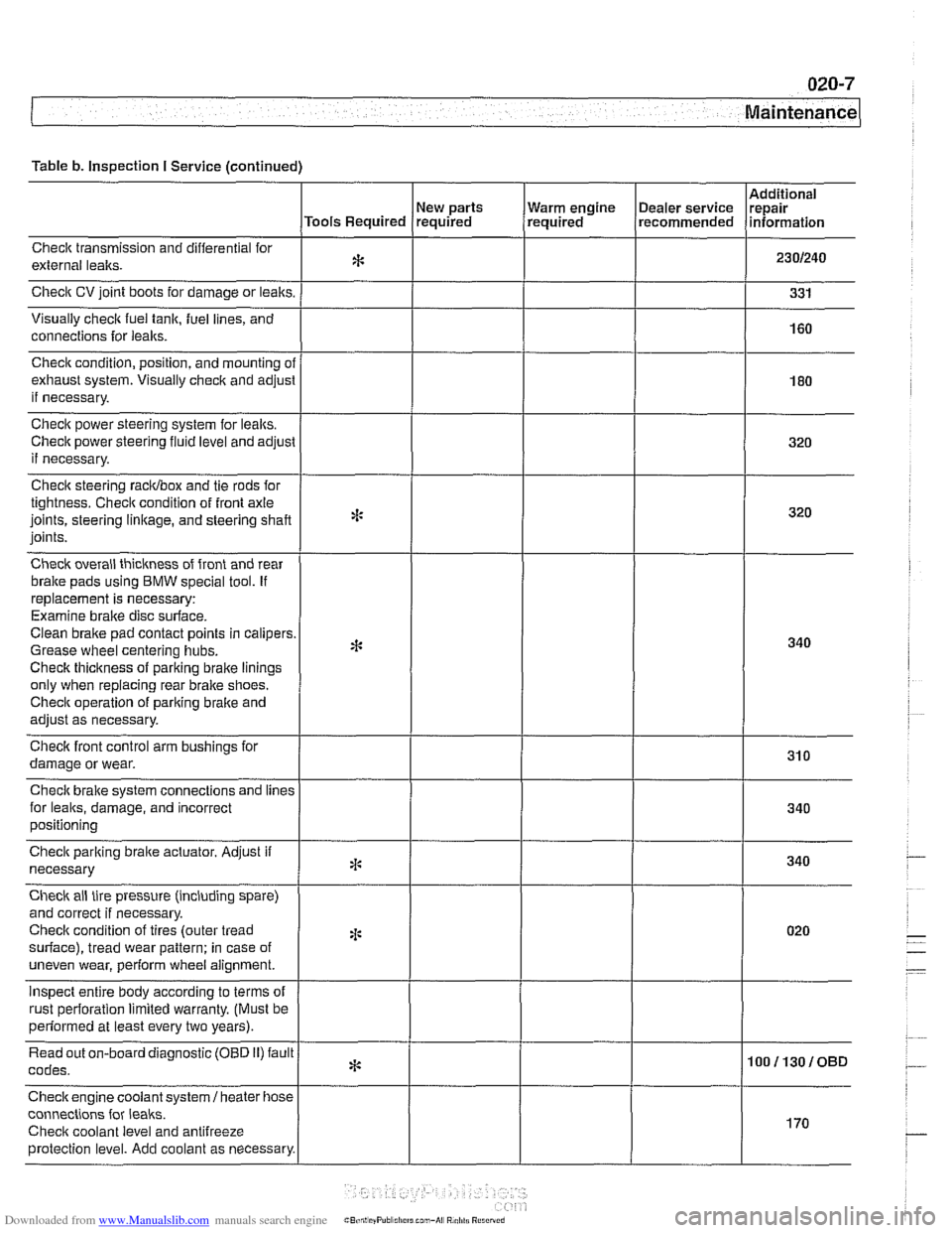
Table b. Inspection I Service (continued)
Checlt transmission and differential for
external lealts.
Check CV joint boots for damage or leaks.
Visually
check fuel tank, fuel lines, and
connections for
leaks.
New parts
Tools Required required
Check condition, position, and mounting
ol
exhaust system. Visually check and adjusl
if necessary.
Check power steering system for lealts.
Check power steering
fluid level and adjust
if necessary.
Check steering racidbox and tie rods for
tightness. Checit condition of front axle
joints, steering
linkage, and steering shaft
joints.
Check overall thickness of front and rear
bralte pads using
BMW special tool. If
replacement is necessary:
Examine brake disc surface.
Clean brake pad contact points in calipers
Grease wheel centering hubs.
Checlt thickness of parking brake linings
only when replacing rear brake shoes.
Checit operation of pariting brake and
adjust as necessary.
Checlt front control arm bushings for
damage or wear.
Check brake system connections and
lines
for leaks, damage, and incorrect
positioning Warm
engine
(~ealer service Irepair , required recommended lnformat~on
Check parking braite actuator. Adjust if
necessary
Check ail tire pressure (including spare)
and correct if necessary.
Checlt condition of tires (outer tread
surface), tread wear pattern: in case of
uneven wear, perform wheel alignment.
inspect entire body according to terms of
rust oerforation limited warrantv. (Must be
*:
4:
2 ~ perfdrmed at least every two years). I
Read out on-board diagnostic (OBD 11) fault
codes.
Checkengine coolant
system1 heater hose
connections for
leaks.
Checit coolant level and antifreeze
protection level. Add coolant as necessary.
* 100113010BD
I
170
Page 48 of 1002
Downloaded from www.Manualslib.com manuals search engine
020-1 6
Maintenance
loose, hose is damaged, or connection is dirty or corroded.
Dried coolant has achalky appearance. Hoses should be firm
and springy. Replace any hose that is cracked, has become
soft and limp, or has been contaminated by oil.
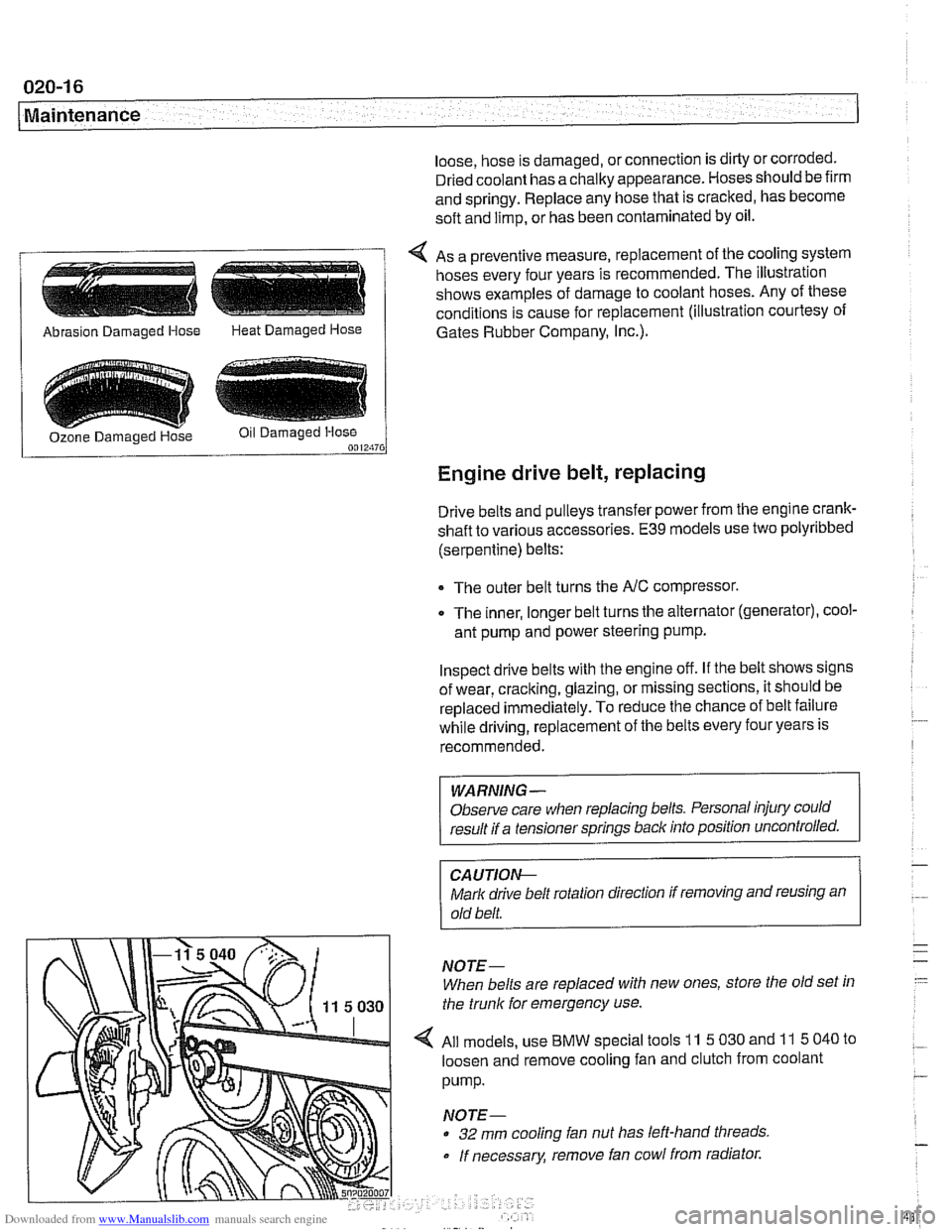
4 As a preventive measure, replacement of the cooling system
hoses every four years is recommended. The illustration
shows examples of damage to coolant hoses. Any of these
conditions is cause for replacement (illustration courtesy of
/ Abrasion Damaged Hose Heat Damaged Hose 1 Gates Rubber Company, I~c.).
Engine drive belt, replacing
Drive belts and pulleys transfer power from the engine crank-
shaft to various accessories.
E39 models use two polyribbed
(serpentine) belts:
The outer belt turns the
NC compressor.
0 The inner, longer belt turns the alternator (generator), cool-
ant pump and power steering pump.
Inspect drive belts with the engine off. If the belt shows signs
of wear, cracking, glazing, or missing sections, it should be
replaced
immediately. To reduce the chance of belt failure
while driving, replacement of the belts every four years is
recommended.
WARNING -
Observe care when replacing belts. Personal injury could
result if a tensioner springs back into position uncontrolled.
CA UTIOI\C
Mark drive belt rotation direction if removing and reusing an
old belt.
NOTE-
When belts are replaced with new ones, store the old set in
the trunk for emergency use.
All models, use
BMW special tools 11 5 030 and 11 5 040 to
loosen and remove cooling fan and clutch from coolant
pump.
NOTE-
32 mm cooling fan nut has left-hand threads
If necessary, remove fan cowl from radiator.
Page 51 of 1002
Downloaded from www.Manualslib.com manuals search engine
Maintenance
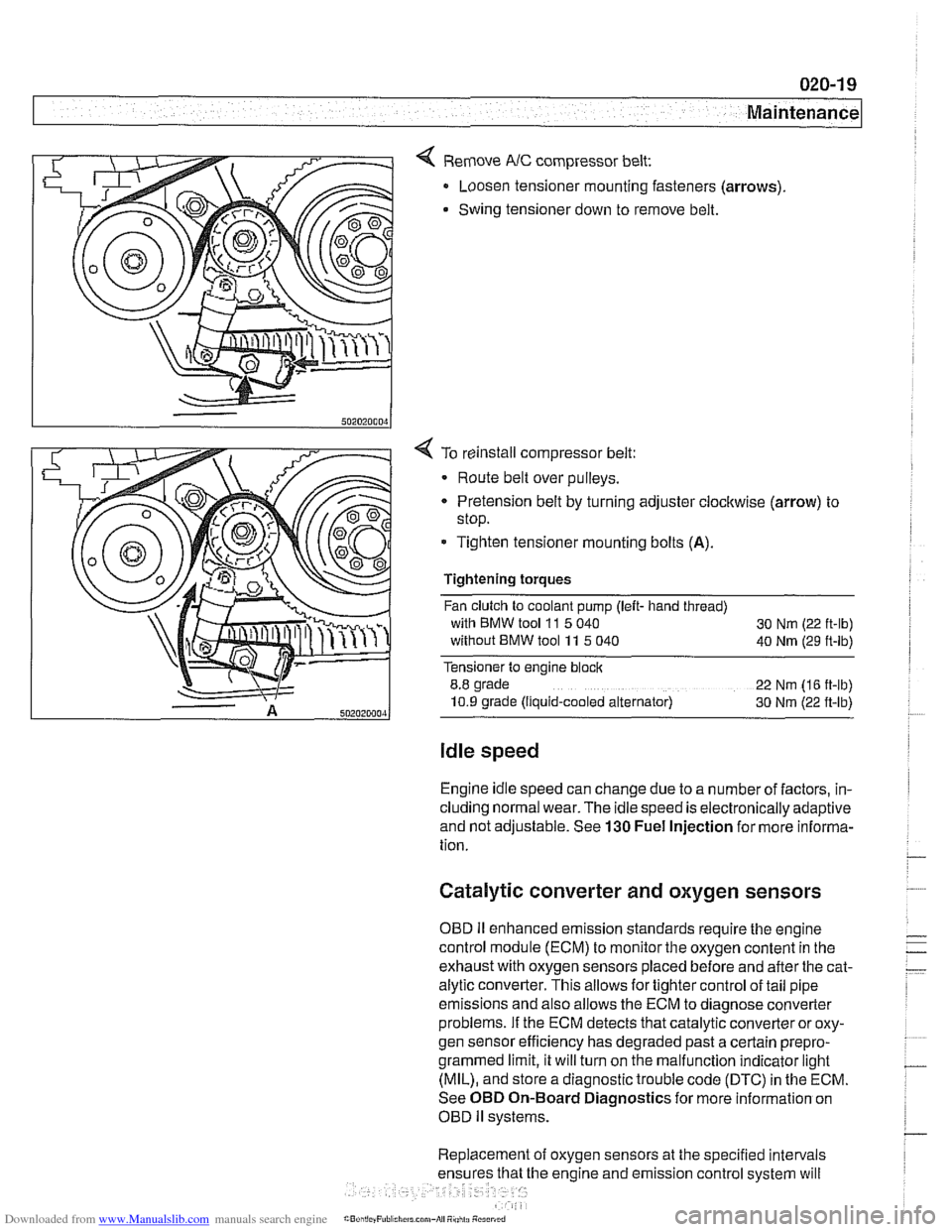
< Remove NC compressor belt:
Loosen tensioner mounting fasteners (arrows)
Swing tensioner down to remove belt.
4 To reinstall compressor belt:
Route belt over pulleys.
* Pretension belt by turning adjuster clockwise (arrow) to
stop.
- Tighten tensioner mounting bolts (A).
Tightening torques
Fan clutch to coolant pump (left- hand thread)
with BMW tool
11 5 040
30 Nm (22 ft-lb)
without BMW tool 11 5 040
40 Nm (29 ft-lb)
Tensioner to engine block
8.8 grade
22 Nm (16 ft-lb)
10.9 grade (Ilquid-cooled alternator) 30 Nm (22 ft-lb)
Idle speed
Engine idle speed can change due to a number of factors, in-
cluding normal wear. The idle speed is electronically adaptive
and not adjustable. See
130 Fuel Injection for more informa-
tion.
Catalytic converter and oxygen sensors
OBD II enhanced emission standards require the engine
control module (ECM) to monitor the oxygen content in the
exhaust with oxygen sensors placed before and after the cat-
alytic converter. This allows for tighter control of tail pipe
emissions and also allows the ECM to diagnose converter
problems. If the ECM detects that catalytic converter or oxy-
gen sensor efficiency has degraded past a certain
prepro-
grammed limit, it will turn on the malfunction indicator light
(MIL), and store a diagnostic trouble code (DTC) in the ECM.
See OBD On-Board Diagnostics for more information on
OBD
ll systems.
Replacement of oxygen sensors at the specified intervals
he engine and emission control system will
Page 52 of 1002
Downloaded from www.Manualslib.com manuals search engine
Maintenance
continue to operate as designed. Extending the replacement
interval may void the emission control warranty coverage.
See
180 Exhaust System for information on replacing the
oxygen sensors.
Tightening torque
Oxvoen sensor to exhaust
manifold 50 Nrn (37 ft-lb)
NOTE-
A special soclet for replacing the oxygen sensor is available
from most automotive parts stores. The soclet has
a groove
cut down one side to allow the sensor to be installed without
damaging the wire harness.
Power steering fluid, checking level
The power steering system is permanently filled and does not
have a drain. Routinely adding ATF is not required unless the
system is leaking.
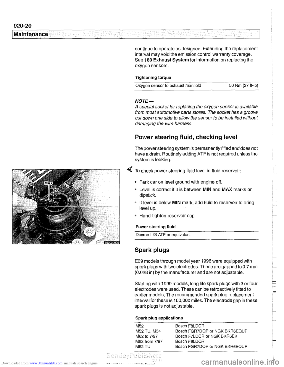
4 To check power steering fluid level in fluid reservoir:
Park car on level ground with engine off.
Level is correct
if it is between MlN and MAX marks on
dipstick.
If level is below
MlN mark, add fluid to reservoir to bring
level up.
* Hand-tighten reservoir cap.
Power steering fluid
Dexron
1iiO ATF or equivalent
Spark plugs
E39 models through model year 1998 were equipped with
spark plugs with two electrodes. These are gapped to
0.7 mm
(0.028 in) by the manufacturer and are not adjustable.
Starting with 1999 models, long life spark plugs with
3 or four
electrodes were used. These can be retroactively fitted to
earlier
models. The recommended spark plug replacement
interval
forthese is 100,000 miles.The electrode gap in these
spark plugs is not adjustable.
Spark plug applications
M52 Bosch FBLDCR
M52 TU, M54 Bosch FGR7DQP or NGK BKRBEQUP
M62 to 7/97 Bosch F7LDCR or NGK BKR6EK
M62 from 7/97 Bosch F9LDCR
M62 TU Bosch FGR7DQP or NGK BKRGEQUP
Page 59 of 1002
Downloaded from www.Manualslib.com manuals search engine
.-. -
Maintenance
Drive axle joint
(CV joint) boots, inspecting
CVjoint protective boots must be closely inspected forcracks
and any other damage that will allow contaminants to get into
the joint.
If the rubber boots fail, the water and dirt that enter
the joint will quickly damage it.
NOTE-
Replacement of the CVjoint boots and inspection of the
joints are described
in 331 Final Drive.
Exhaust system, inspecting
Exhaust system life varies widely according to driving habits
and environmental conditions. If short-distance driving pre-
dominates, the moisture and condensation in the system will
not fully dry out. This will lead to early corrosion damage and
more frequent replacement.
Scheduled maintenance of the exhaust system is limited to
inspection:
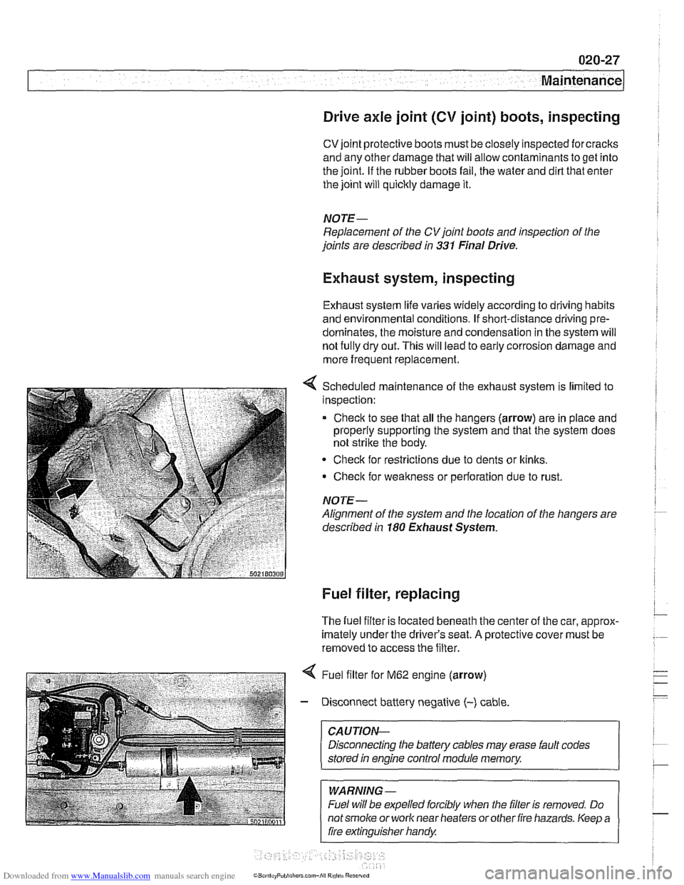
* Check to see that all the hangers (arrow) are in place and
properly supporting the system and that the system does
not strike the body.
Check for restrictions due to dents or
kinlts,
Check for weakness or perforation due to rust.
NOTE-
Alignment of the system and the location of the hangers are
described in
180 Exhaust System.
Fuel filter, replacing
The fuel filter is located beneath the center of the car, approx-
imately under the driver's seat.
A protective cover must be
removed to access the filter.
4 Fuel filter for M62 engine (arrow)
- Disconnect battery negative (-) cable
CAUTIOI\C
Disconnecting the battery cables may erase fault codes
stored
in engine control module memory.
WARNING -
Fuel will be expelled forcibly when the filter is removed. Do
notsmoke or work near heaters orother fire hazards. Keep a
fire extinguisher handy
Page 69 of 1002
Downloaded from www.Manualslib.com manuals search engine
Engine identifying features
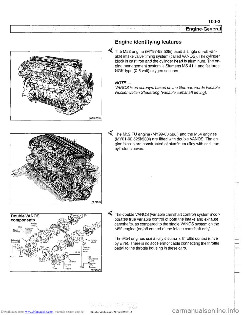
4 The M52 engine (MY97-98 528i) used a single on-off vari-
able intake valve timing system (called VANOS). The cylinder
block is cast iron and the cylinder head is aluminum. The en-
gine management system is Siemens MS 41
.I and features
NGK-type (0-5 volt) oxygen sensors.
NOTE-
VANOS is an acronym based on the German words Variable
Nocltenwellen Steuerung (variable camshaft timing).
4 The M52 TU engine (MY99-00 5281) and the M54 engines
(MY01-02 525il530i) are fitted with double VANOS. The en-
gine
blocits are constructed of aluminum alloy with cast iron
cylinder sleeves.
4 The double VANOS (variable camshaft control) system incor-
porates true variable control of both the
intake and exhaust
camshafts, as compared to the single VANOS system on the
M52 engine
(onloff control of the intaite camshaft only).
The M54 engines use a fully electronic throttle control (drive
by wire). There is no accelerator cable connecting the throttle
pedal to the throttle housing in these cars.