engine control system BMW 528i 1998 E39 Service Manual
[x] Cancel search | Manufacturer: BMW, Model Year: 1998, Model line: 528i, Model: BMW 528i 1998 E39Pages: 1002
Page 360 of 1002
Downloaded from www.Manualslib.com manuals search engine
120-1 2
ignition System
Crankshaftspeedsensor
Crankshaft speed sensor, replacing (M52, M52 TU and
M54 engines)
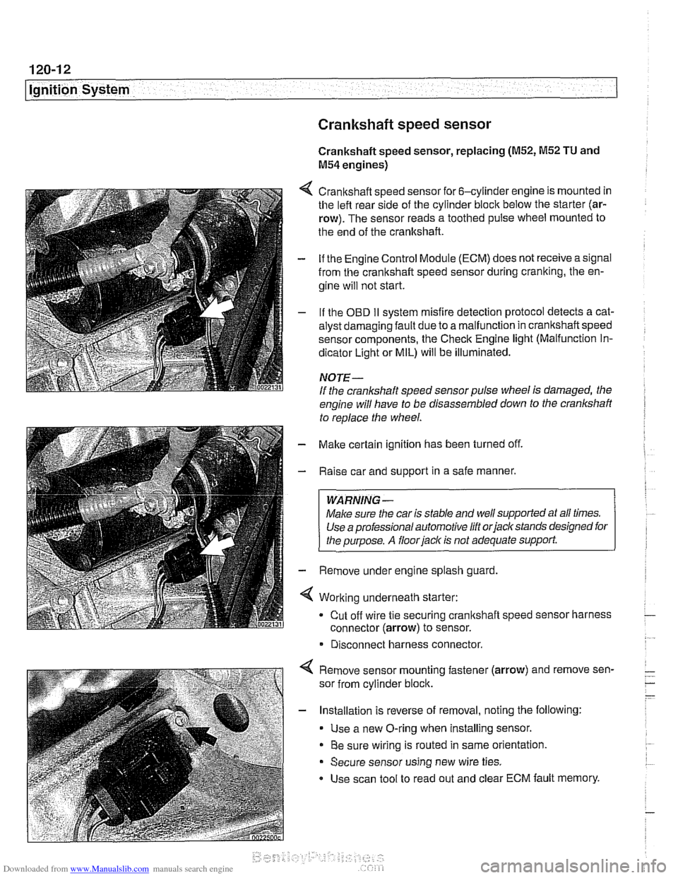
4 Crankshaft speed sensor for 6-cylinder engine is mounted in
the left rear side of the cylinder block below the starter (ar-
row). The sensor reads a toothed pulse wheel mounted to
the end of the crankshaft.
- if the Engine Control Module (ECM) does not receive a signal
from the crankshaft speed sensor during cranking, the en-
gine will not start.
- If the OBD II svstem misfire detection ~rotocol detects a cat- - - ~~
alysr oarnagin; faLlt oJe to a ma I-nclion in crandshafi speeo
sensor components. Ine Check Engine
lignr (Malfuncrion In-
dicator Light or MIL) will be illuminated.
NOTE-
If the crankshaft speed sensor pulse wheel is damaged, the
engine will have to be disassembled down to the crankshaft
to
reolace the wheel.
- Make certain ignition has been turned off.
- Raise car and support in a safe manner.
WARNING -
Make sure the car is stable and well supported at all times.
Use a professional automotive lift orjacltstands designed for
the ouroose.
A floor iaclc is not adequate support.
- Remove under engine splash guard
4 Working underneath starter:
Cut off wire tie securing crankshaft speed sensor harness
connector (arrow) to sensor.
* Disconnect harness connector.
4 Remove sensor mounting fastener (arrow) and remove sen-
sor from cylinder block.
- Installation is reverse of removal, noting the following:
Use a new O-ring when installing sensor.
Be sure wiring is routed in same orientation.
Secure sensor using new wire ties.
Use scan tool to read out and clear ECM fault memory.
Page 361 of 1002
Downloaded from www.Manualslib.com manuals search engine
ignition System
Crankshaft speed sensor, replacing (M62 and M62TU
engines)
The crankshaft speed sensor reads a toothed pulse wheel
mounted on the flywheel.
If the Engine Control Module(ECM)
does not receive an impulse signal from the crankshaft speed
sensor during
cranking, the engine will not start. If the OBD II
system misfire detection protocol detects a catalyst damag-
ing fault due to a malfunction in the crankshaft speed sensor
components, the Check Engine light (Malfunction
Indicator
Light or MIL) will be Illuminated.
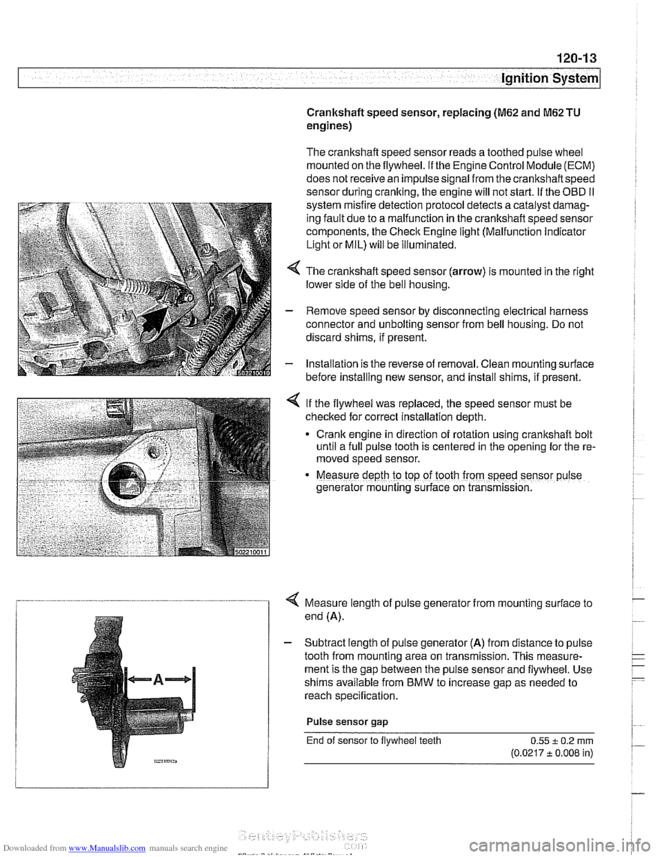
4 The crankshaft speed sensor (arrow) is mounted in the right
lower side of the bell housing.
- Remove speed sensor by disconnecting electrical harness
connector and unbolting sensor from bell housing. Do not
discard shims, if present.
- Installation is the reverse of removal. Clean mounting surface
before installing new sensor, and install shims, if present.
< If the flywheel was replaced, the speed sensor must be
checked for correct installation depth.
* Crank engine in direction of rotation using crankshaft bolt
until a full pulse tooth is centered in the opening for the re-
moved speed sensor.
Measure depth ro top of tooth from speed sensor p~lse
generator mounting s~rface on transmission.
4 Measure length of pulse generator from mounting surface to
end (A).
- Subtract length of pulse generator (A) from distance to pulse
tooth from mounting area on transmission. This measure-
ment is the gap between the pulse sensor and flywheel. Use
shims available from BMW to increase gap as needed to
reach specification.
Pulse sensor
gap
End of sensor to flywheel teeth 0.55 + 0.2 rnrn
(0.0217 t 0.008 in)
Page 362 of 1002
Downloaded from www.Manualslib.com manuals search engine
I Ignition System
Camshaft position sensors
The camshaft position sensors are used by the englne man-
agement system for VANOS control, sequential fuel injection
and knock control.
Intake camshaft position sensor, replacing
(M52,M52 TU
and M54 engines)
- Make certain ignition has been turned off.
- Remove plastic cover from above fuel injectors by prying off
bolt covers and removing cover mounting bolts.
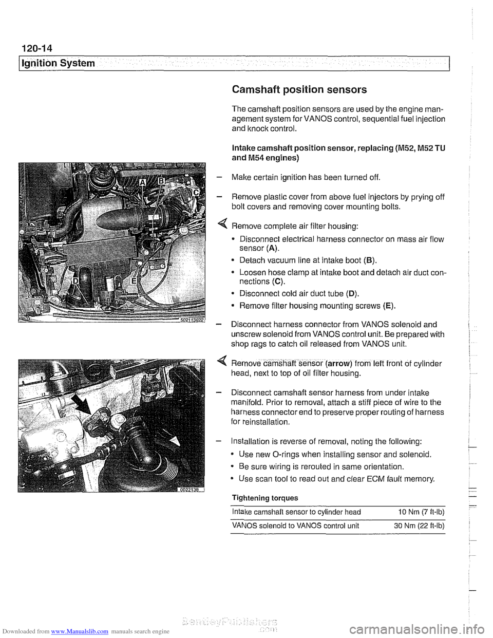
Remove complete air filter housing:
Disconnect electrical harness connector on mass air flow
sensor
(A).
Detach vacuum line at intake boot (B).
Loosen hose clamp at intake boot and detach air duct con-
nections
(C).
* Disconnect cold air duct tube (D).
Remove filter housing mounting screws (E).
- Disconnect harness connector from VANOS solenoid and
unscrew solenoid from VANOS control unit. Be prepared with
shop rags to catch oil released from VANOS unit.
Remove camshaft sensor (arrow) from
left front of cyl~nder
head, next to top of oil filter housing.
Disconnect camshaft sensor harness from under intake
manifold. Prior to removal, attach a stiff piece of wire to the
harness connector end to preserve proper routing of harness
for reinstallation.
Installation is reverse of removal, noting the following:
Use new O-rings when installing sensor and solenoid.
Be sure wiring is rerouted in same orientation.
Use scan tool to read out and clear
ECM fault memory
Tightening torques
-
Intake camshaft sensor to cylinder head 10 Nrn (7 ft-lb)
VANOS solenoid to VANOS control unit 30 Nm (22 ft-lb)
Page 367 of 1002
Downloaded from www.Manualslib.com manuals search engine
121-1
121 Battery. Starter. Alternator
General ........................... .I2 1.2
Special tools ........................ .I2 1.2
Engine electrical system ............... .I2 1.2
Battery Safety Terminal ............... .I2 1.3
Warnings and cautions ................. 121 -4
Battery ............................ 121-5
Battery testing ...................... .I2 1.5
Hydrometer testing ................... .I2 1.5
Battery open-circuit voltage test ......... .I2 1.6
Battery load voltage test ................ 121 -6
Closed-circuit current measurement ..... .I2 1.7
Battery charging ...................... 121 -9
Battery safety terminal, replacing ......... 121-9
Alternator (generator) ............. .I2 1.10
Alternator. basic .................... .I2 1.11
Alternator with multi-function
control (MFR)
...................... .I2 1.11
Water-cooled alternator ............... 121 -12
Charging System Troubleshooting . 121-12
Charging system quick-check .......... 121-13
Charging system. checking ............ 121-13
Alternator. removing and installing
(6-cylinder engine)
.................. 121 -1 5
Alternator. removing and installing
(M62 engine. air cooled)
.............. 121-16
Alternator. removing and installing
(M62 TU engine. water cooled) ......... 121-1 8
Starter ........................... 121 -1 9
Starter troubleshooting ............... 121 -1 9
Starter. removing and installing
(6-cylinder engine)
.................. 121-20
Starter. removing and installing
(V-8 engine)
........................ 121 -21
Solenoid switch. removing and installing . . 121-23
Page 369 of 1002
Downloaded from www.Manualslib.com manuals search engine
Battery, Starter, ~lternatorl
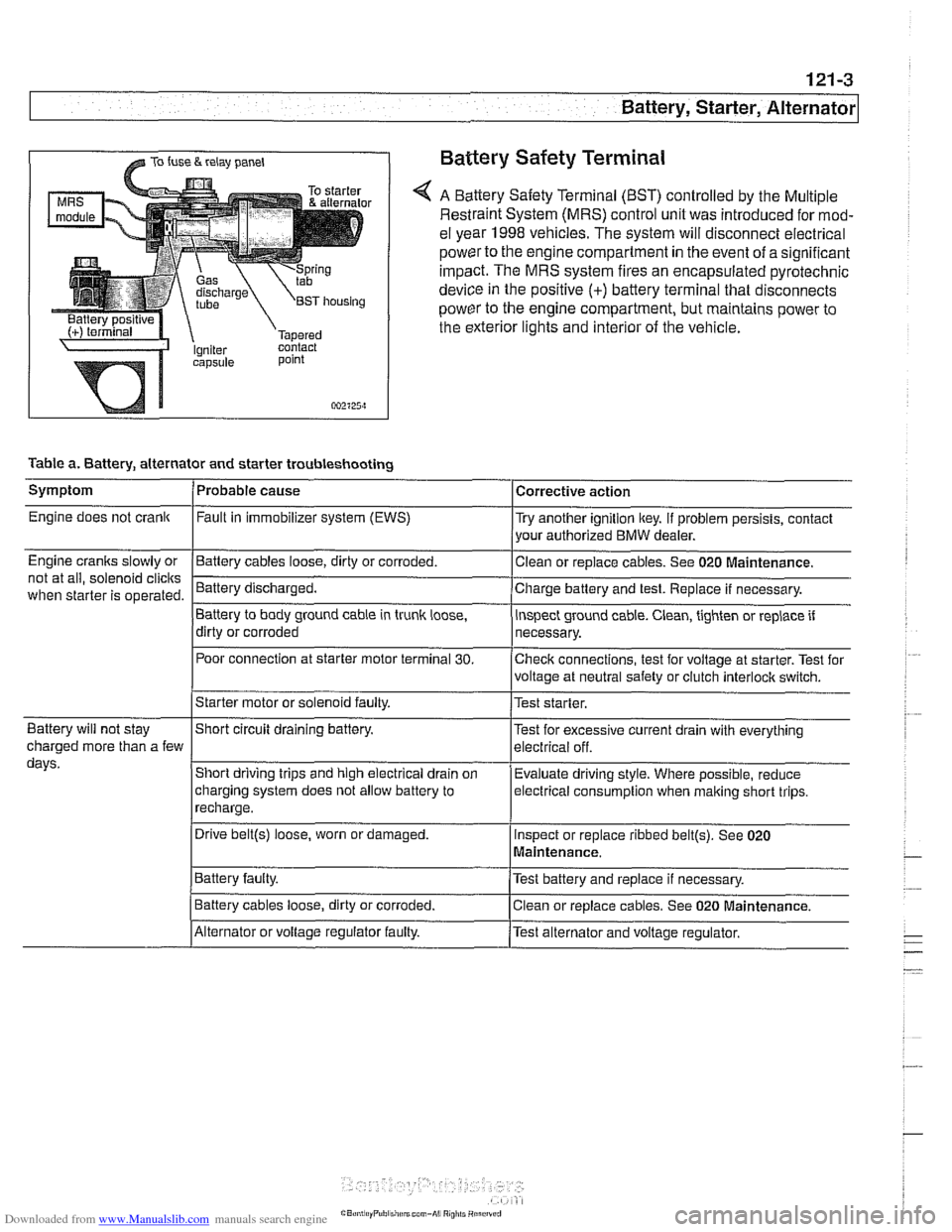
@ TO fuse & relay panel Battery Safety Terminal
A Battery Safety Terminal (BST) controlled by the Multiple
Restraint System (MRS) control unit was introduced for mod-
el year 1998
vehicles. The system will disconnect electrical
power to the engine compartment
in the event of a significant
impact. The MRS system fires an encapsulated pyrotechnic
device
in the positive (+) battery terminal that disconnects
power to the engine compartment, but maintains power to
the exterior lights and interior of the vehicle.
point
002125~1
Table a. Battery, alternator and starter troubleshooting
1-
/Starter motor or solenoid faulty. l~est starter.
Symptom
Engine does not crank
Engine cranks slowly or
not at all, solenoid
clicits
when starter is operated.
I I
Battery will not stay IShort circuit draining battery. l~est for excessive current drain with everything
Probable cause
Fault
in immobilizer system (EWS)
-Clean Battery cables loose, dirty or corroded.
Battery discharged.
Battery to body ground cable in trunk
loose,
dirty or corroded
Poor connection at starter motor terminal
30.
Corrective action
Try another ignition key. If problem persists, contact
your authorized BMW dealer.
or replace cables. See 020
~aintenance.
Charge battery and test. Replace if necessary.
inspect ground cable. Clean, tighten or replace if
necessary.
Checlc connections, test for voltage at starter. Test for
voltage at neutral safety or clutch
interloclc switch.
charged more than a few
days.
I~atter~ faulty. /Test battery and replace if necessary.
Short driving trips and high electrical drain
on
charging system does not allow battery to
recharge.
. I
I Battery cables loose, dirty or corroded. Iclean or replace cables. See 020 Maintenance.
Evaluate driving
style. Where possible, reduce
electrical
consumption when malting short trips.
Drive
belt@) loose, worn or damaged.
IAlternator or voltage regulator faulty. /Test alternator and voltage regulator.
Inspect
or replace ribbed
belt@). See 020
Maintenance.
Page 377 of 1002
Downloaded from www.Manualslib.com manuals search engine
121-11
Battery, Starter, ~lternatorl
Alternator 1997 - 98 5281 1997 540i
/-- -----,
I'
-----------
F15 / 7.5A/ :
&.. .... , 30 1 Xi0015
Battery
Hol in run 61 E (D+) Alternator
and stsrt
lBL
(Generator)
1 .--------,charge , . I , indicator I xGoli i
I <"9,7,a,T
Alternator, basic
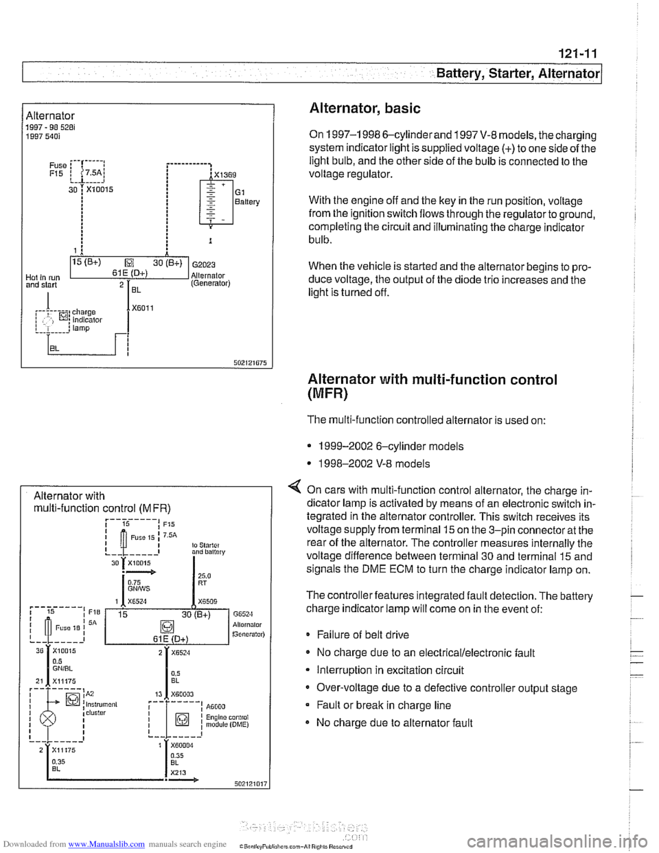
On 1997-1 998 6-cylinderand 1997 V-8 models, the charging
system indicator light is supplied voltage
(+) to one side of the
light bulb, and the other side of the bulb is connected to the
voltage regulator.
With the engine off and the key in the run position, voltage
from the ignition switch flows through the regulator to ground,
completing the circuit and illuminating the charge indicator
bulb.
When the vehicle is started and the alternator begins to pro-
duce voltage, the output of the diode trio increases and the
light is turned off.
Alternator with multi-function control
(MFR)
Alternator with multi-function control
(MFR)
The multi-function controlled alternator is used on:
* 1999-2002 6-cylinder models
* 1998-2002 V-8 models
4 On cars with multi-function control alternator, the charge in-
dicator lamp is activated by means of an electronic switch in-
tegrated in the alternator controller. This switch receives its
voltage supply from terminal
15 on the 3-pin connector at the
rear of the alternator. The controller measures internally the
voltage difference between terminal 30 and terminal
15 and
signals the DME ECM to turn the charge indicator lamp on.
The controller features integrated fault detection. The battery
charge indicator lamp will come on in the event of:
* Failure of belt drive
No charge due to an
electrical/electronic fault
Interruption in excitation circuit
Over-voltage due to a defective controller output stage Fault or break in charge line
No charge due to alternator fault
Page 379 of 1002
Downloaded from www.Manualslib.com manuals search engine
Battery, Starter, ~lternatorl
Charging system quick-check
Use a digital multimeter to measure voltage across the bat-
tery terminals with key off and then again with engine running.
Battery voltage should be about 12.6 volts with key off and be-
tween 13.5 and 14.5 volts with engine running.
NOTE-
The regulated voltage (engine running) should be between
13.2 and 14.5, depending on temperature andoperating con-
ditions.
If the voltage is higher than 14.8, the voltage regula-
tor or
mulitfunction controller is most likely faulty
Check for clean and tight battery cables. Check ground cable
running from negative
(-) battery terminal to chassis and
ground cable running from engine to chassis. Check alterna-
tor drive belt condition and tension.
Charging system, checking
CAUTIOI\C
* Do not disconnect the battery while the engine is running.
Damage to the alternator and/or engine electronic systems
may result.
Only use a digital multimeter when testing charging
system components.
--7
4 Turn ignition key on. Check that battery warning light comes
on.
NOTE-
If the warning light does not come on, repair bulb or wiring
faults before continuing to checlc the charging system.
/ Charge indicator
502820805
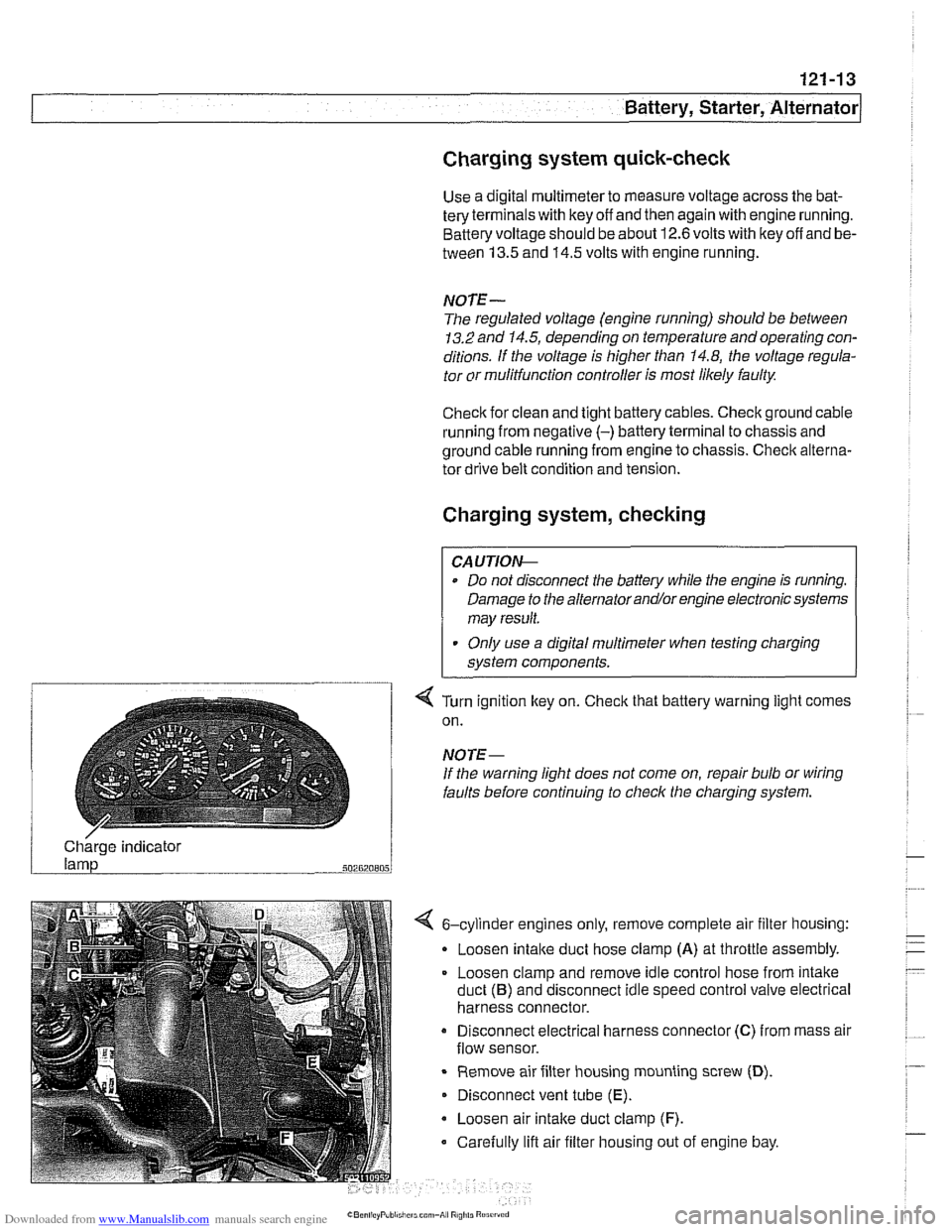
4 6-cylinder engines only, remove complete air filter housing:
Loosen
intake duct hose clamp (A) at throttle assembly.
Loosen clamp and remove idle control hose from intake
duct
(B) and disconnect idle speed control valve electrical
harness connector.
Disconnect electrical harness connector
(C) from mass air
flow sensor.
Remove air filter housing mounting screw
(D).
Disconnect vent tube (E).
Loosen air intake duct clamp (F).
Carefully lift air filter housing out of engine bay.
Page 381 of 1002
Downloaded from www.Manualslib.com manuals search engine
Battery, Starter, ~lternatorl
Alternator, removing and installing
(6-cylinder engine)
A replacement alternator should have the same rating as the
original. Alternator manufacturer and ampere rating are nor-
mally marked on the alternator housing.
- Disconnect negative (-) battery cable.
CAUTION-
Prior to disconnecting the batteg read the battery discon-
nection cautions given
in 001 General Warnings and Cau-
I tions.
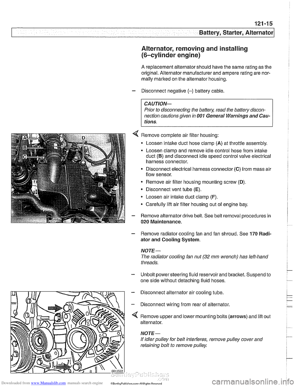
Remove complete air filter housing:
Loosen intake duct hose clamp
(A) at throttle assembly.
Loosen clamp and remove idle control hose from intake
duct
(B) and disconnect idle speed control valve electrical
harness connector.
Disconnect electrical harness connector
(C) from mass air
flow sensor.
* Remove air filter housing mounting screw (D),
Disconnect vent tube (E).
Loosen air intake duct clamp (F).
Carefully lifl air filter housing out of engine bay.
Remove alternator drive belt. See belt removal procedures in
020 Maintenance.
- Remove radiator cooling fan and fan shroud. See 170 Radi-
ator and Cooling System.
NOTE-
The radiator cooling fan nut (32 mm wrench) has left-hand
threads.
- Unbolt power steering fluid reservoir and bracket. Suspend to
one side without detaching fluid hoses.
- Disconnect alternator air cooling tube.
- Disconnect wiring from rear of alternator.
'4 Remove upper and lower mounting bolts (arrows) and lift
alternator.
If idler pulley for belt interferes, remove pulley cover and
retaining bolt to remove pulley. out
Page 386 of 1002
Downloaded from www.Manualslib.com manuals search engine
I Battery, Starter, Alternator
- Check for battery voltage at terminal 50 of starter motor with
key in start position. If voltage is not present, check wiring be-
tween ignition switch and starter terminal. Check the EWS
system and other inputs that disrupt terminal
56 to the start-
er. See ELE Electrical
Wiring Diagrams. If voltage is
present and no other visible wiring faults can be found, prob-
lem is most likely in starter motor.
Starter, removing and installing
(6-cylinder engine)
The starter is removed from below. Access to starter bolts is
difficult. Be sure to have the proper tools on hand before pro-
ceeding.
NOTE-
Access to the starter wiring is very limited. Forbetteraccess,
it may be necessary to remove the intake manifold.
- Disconnect negative (-) battery cable.
CAUTIOI\C
Prior to disconnecting the battern read the baltery discon-
nection cautions
in OOlGeneral Cautions and Warnings.
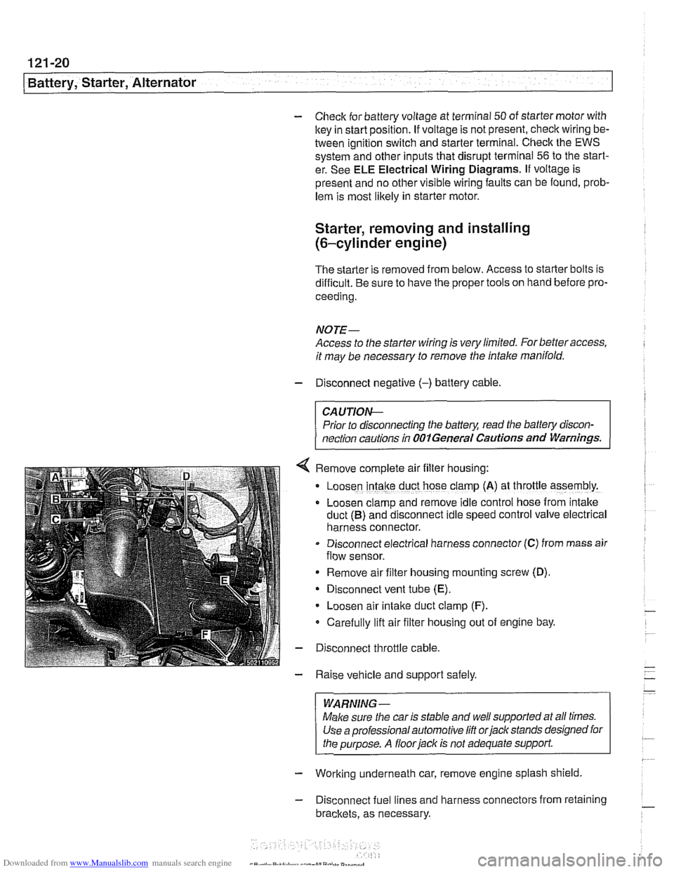
Remove complete air filter hous~ng:
Loosen intake duct hose clamp (A) at throttle assembly.
Loosen clamp and remove idle control hose from intake
duct
(B) and disconnect idle speed control valve electrical
harness connector.
Disconnect electrical harness connector
(C) from mass air
flow sensor.
Remove air filter housing mounting screw (D)
Disconnect vent tube
(E).
Loosen air intake duct clamp (F).
Carefully lift air filter housing out of engine bay.
Disconnect throttle cable.
Raise vehicle and support safely.
WARNING-
Make sure the car is stable and well supported at all times.
Use a professional automotive
lift orjack stands designed for
the purpose. A
floorjaclc is not adequate support
- Working underneath car, remove engine splash shield
- Disconnect fuel lines and harness connectors from retaining
brackets, as necessary.
Page 391 of 1002
Downloaded from www.Manualslib.com manuals search engine
130-1
130 Fuel injection
General ........................... .I3 0.2
Tools and test equipment .............. .I3 0.3
Warnings and cautions ................ .I3 0.5
Fuel Supply ....................... .I3 0.6
Relieving system fuel pressure .......... .I3 0.6
Siemens MS 41 . 1. ................... 1 30-7
ECM relay. testing .................... .I3 0.7
Mass air flow (MAF) sensor.
checking and replacing
................ .I3 0.9
Engine coolant temperature (ECT) sensor.
testing and replacing
.................. 130-10
Intake air temperature (IAT) sensor.
testing and replacing
................. .I3 0.1 1
Throttle position sensor (TPS).
testing and replacing
.................. 130-1 2
ldle speed control valve.
checking and replacing
............... .I3 0.1 3
Fuel injectors. checking and replacing .... 130-15
Evaporative emissions. overview ....... .I3 0.1 6
Secondary air injection. overview ....... .I3 0-17
Engine control module (ECM).
removing and installing
................ 130-18
Siemens MS 41.1 ECM pin assignments . .I3 0.19
Siemens MS 42.0 and MS 43.0. ..... .I3 0.23
ECM relay. testing ................... .I3 0.27
Mass air flow (MAF) sensor.
checking and replacing
............... .I3 0.28
Engine coolant temperature (ECT) sensor.
testing and replacing
................. .I3 0.30
Intake air temperature (IAT) sensor.
testing and replacing
................. .I3 0.31
MS 42.0 throttle valve assembly. replacing . 130-32
MS 43.0 throttle valve assembly. replacing . 130-35
Throttle cable. adjusting (MS 42.0) ...... .I3 0.38
ldle speed control valve. checking
and replacing
....................... .I3 0.38
Evaporative emissions control diagrams . . 130- 39
Evaporative emissions control.
(MS
42.0 and MS 43.0). .............. .I3 0.39
Engine control module (ECM).
removing and installing
................ 130-40
Siemens MS 42.0 and MS 43.0
ECM pin assignments ................. 130-41
Bosch M5.2 (M62 up to 911997)
BOSC~ M5.2.1 (M62 911997 to 911998) 130-46
M5.2 system features ................. 130-47
M5.2.1 system features ............... 130-47
ECM relay. testing ................... 130-49
Oxygen sensors. checking ............. 130-51
Fuel injectors. checking and replacing .... 130-52
Mass air flow (MAF) sensor. replacing .... 130-53
ldle speed control valve. testing
and replacing
....................... 130-54
Throttle position sensor (TPS).
testing and replacing
................. 130-55
Engine coolant temperature (ECT) sensor.
testing and replacing
................. 130-55
Intake air temperature (IAT) sensor.
testing and replacing
................. 130-57
Auxiliary throttle valve (ADS) (M62 and
M62 TU engine). replacing ..... 130-57
Evaporative system pressure
leak diagnosis. overview
(5.2.1 only) ..... 130-58
Bosch 5.2 ECM pin assignments
(M62 UP to 911 997) ................... 130-59
~osch 5.2.1 ECM pin assignments
(M62 911 997 to 911 998) ............... 130-62
BOSC~ ME 7.2 ..................... 1 30-66
ME 7.2 system overview ............... 130-67
EDK adaptation ..................... 130-69
ECM relay. checking .................. 130-69
Engine coolant temperature
(ECT) sensor. testing
................. 130-71
Engine coolant temperature
(ECT) sensor. replacing
............... 130-71
Oxygen sensors. replacing ............. 130-72
Fuel injectors. removing and installing .... 130-72
Mass air flow (MAF) sensor.
removing and installing
................ 130-73
Evaporative system pressure
leak diagnosis. overview
............... 130-74
Secondary air injection. overview ........ 130-75
Bosch ME 7.2 ECM pin assignments .... 130-76