engine control system BMW 528i 1998 E39 Owner's Guide
[x] Cancel search | Manufacturer: BMW, Model Year: 1998, Model line: 528i, Model: BMW 528i 1998 E39Pages: 1002
Page 287 of 1002
Downloaded from www.Manualslib.com manuals search engine
... -.
Camshaft Timing chain1
Timing chains, removing
(M52 TU and M54 engines)
Camshaft timing chain removal requires that the oil pan be re-
moved. See
119 Lubrication System. Also required is re-
moval of the VANOS control
unit and disassembly of the
intake and exhaust camshaft sprocket assemblies as de-
scribed earlier in this repair group.
Special BMW
service tools are needed for timing chain re-
moval and installation. The special tools assure proper timing
of the valvetrain. Precise
marlts to set the timing on the cam:
shafts are not provided for reassembly. Read the procedures
through before beginning the job.
CA
UTION-
If the camshafts are not properly timed, the pistons can con-
tact the valves.
- D~sconnect negative (-) cable from battery.
CAUTION-
* Disconnecting the battery may erase fault code@) stored in
control module memory. Check for fault codes using spe-
cial
BMW diagnostic equipment.
Prior to disconnecting the battery, read the battery dis-
connection
cautfons given in 001 General Cautions
and
Warninqs.
- Remove VANOS control unit. See VANOS control unit, re-
moving
(M52 TU and M54 engines).
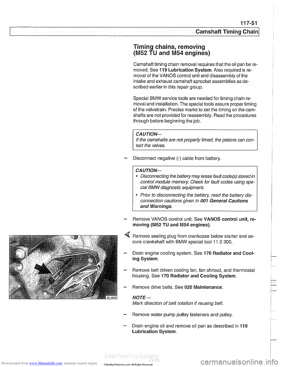
Remove sealing plug from crankcase below starter and se-
cure crankshaft with
BMW special tool ll 2 300.
Drain engine cooling system. See 170 Radiator and Cool-
ing System.
Remove belt driven cooling fan, fan shroud, and thermostat
housing. See
170 Radiator and Cooling System.
Remove drive belts. See
020 Maintenance.
NOTE-
Mark direction of belt rotation if reusing belt.
- Remove water pump pulley fasteners and pulley.
- Drain engine oil and remove oil pan as described in 119
Lubrication System.
Page 302 of 1002
Downloaded from www.Manualslib.com manuals search engine
11 7-66
I Camshaft Timing Chain
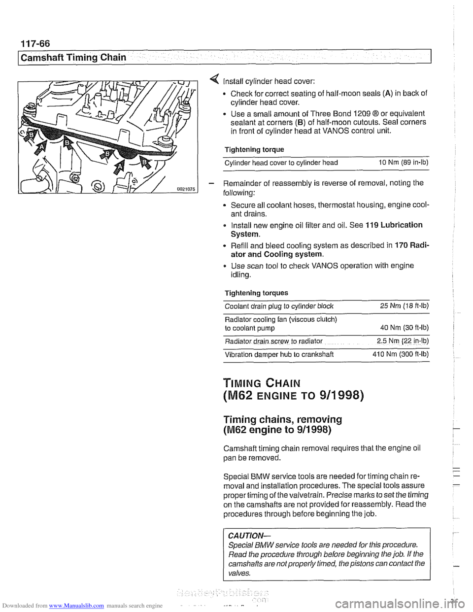
4 install cylinder head cover:
Check for correct seating of half-moon seals
(A) in back of
cylinder head cover.
Use a small amount of Three Bond
1209 8 or equivalent
sealant at corners
(B) of half-moon cutouts. Seal corners
in front of cylinder head at VANOS control unit.
Tightening torque
Cylinder head cover to cylinder head
10 Nm (89 in-lb)
- Remainder of reassembly is reverse of removal, noting the
following:
Secure all coolant hoses, thermostat housing, engine cool-
ant drains.
Install new engine oil filter and oil. See
119 Lubrication
System.
Refill and bleed cooling system as described in
170 Radi-
ator and Cooling system.
Use scan tool to check VANOS operation with engine
idling.
Tightening torques Coolant drain plug to cylinder block
25 Nm (18 ft-lb)
Radiator cooling fan (viscous clutch)
to coolant pump
40 Nm (30 ft-lb)
Radiator drain screw to radrator 2.5 Nm (22 in-lb)
Vibration damper hub to crankshaft 41 0 Nm
(300 ft-ib)
TIMING CHAIN
(M62 ENGINE TO 911998)
Timing chains, removing
(M62 engine to 911 998)
Camshaft timing chain removal requires that the engine oil
pan be removed.
Special
BMW service tools are needed for timing chain re-
moval and installation procedures. The special tools assure
propertiming of thevaivetrain. Precise marks to set the timing
on the camshafts are not provided for reassembly. Read the
procedures through before beginning the job.
CAUTION-
Special BMW service tools are needed for this procedure.
Read the procedure through before beginning the job. If the
camshafts are notproperly timed, the pistons can contact the
valves.
Page 307 of 1002
Downloaded from www.Manualslib.com manuals search engine
Camshaft Timing chain1
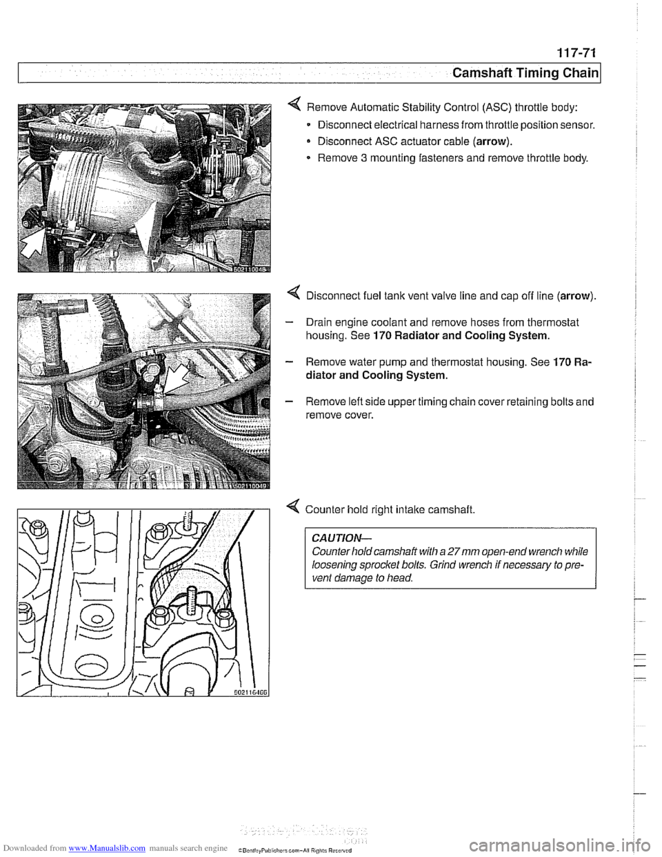
< Remove Automatic Stability Control (ASC) throttle body:
Disconnect electrical harness from throttle position sensor.
Disconnect ASC actuator cable (arrow).
Remove
3 mounting fasteners and remove throttle body.
4 Disconnect fuel tank vent valve line and cap off line (arrow).
- Drain engine coolant and remove hoses from thermostat
housing. See
170 Radiator and Cooling System.
- Remove water pump and thermostat housing. See 170 Ra-
diator and Cooling System.
- Remove left side upper timing chain cover retaining bolts and
remove cover.
4 Counter hold right intake camshaft
CAUTION-
Counter hold camshaft with a 27mm open-end wrench while
loosening sprocket bolts. Grind wrench if necessary to pre-
vent damage to head.
Page 342 of 1002
Downloaded from www.Manualslib.com manuals search engine
/Lubrication System
Oil pump, removing and installing
(&cylinder)
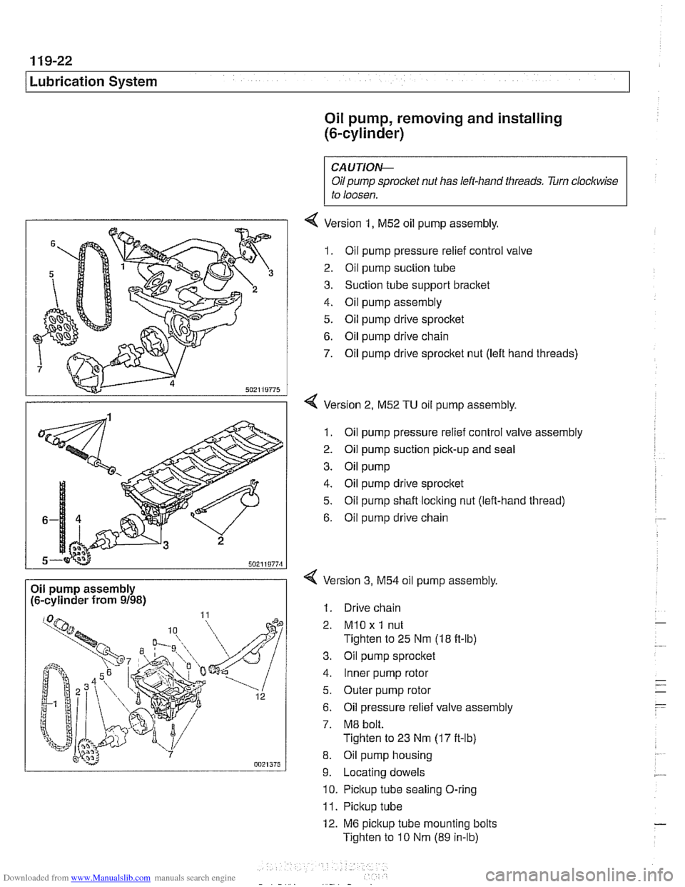
Oil pump assembly
(6-cylinder from 9/98)
CAUTIOI\C
Oil pump sproclcet nut has left-hand threads. Turn clockwise
to loosen.
4 Version 1, M52 oil pump assembly.
1. Oil pump pressure relief control valve
2. Oil pump suction tube
3. Suction tube support bracket
4. Oil pump assembly
5. Oil pump drive sprocltet
6. Oil pump drive chain
7. Oil pump drive sprocket nut (left hand threads)
4 Version 2, M52 TU oil pump assembly.
1. Oil pump pressure relief control valve assembly
2. Oil pump suction pick-up and seal
3. Oil pump
4. Oil pump drive sprocket
5. Oil pump shaft locking nut (left-hand thread)
6. Oil pump drive chain
Version
3, M54 oil pump assembly,
1. Drive chain
2.
MlO x 1 nut
Tighten to 25 Nm (18 ft-lb)
3. Oil pump sprocket
4. Inner pump rotor
5. Outer pump rotor
6. Oil pressure relief valve assembly
7. M8 bolt.
Tighten to 23 Nm
(17 it-lb)
8. Oil pump housing
9. Locating dowels
10. Pickup tube sealing O-ring
11. Pickup tube
12. M6 pickup tube mounting bolts
Tighten to
10 Nm (89 in-lb)
Page 346 of 1002
Downloaded from www.Manualslib.com manuals search engine
11 9-26
/Lubrication System
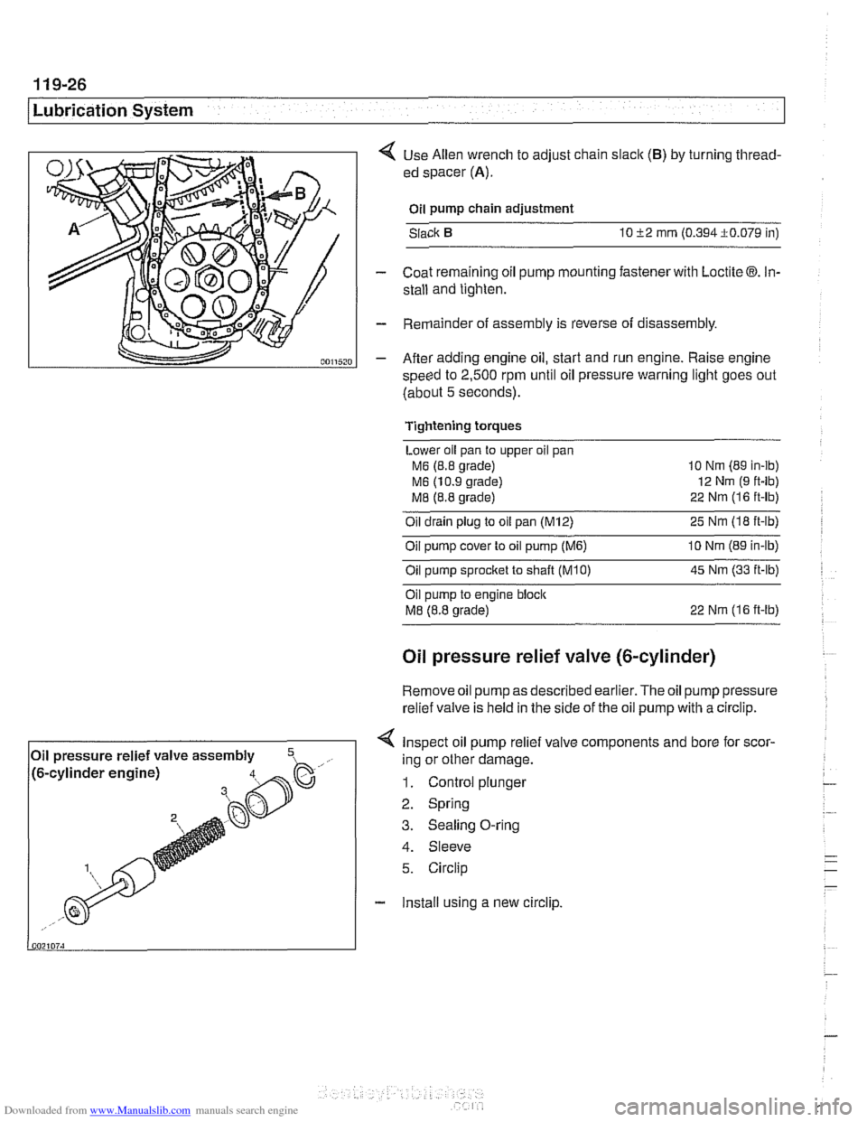
< Use Allen wrench to adjust chain slaclc (B) by turning thread-
ed spacer
(A).
Oil pump chain adjustment
Slack
10 52 mrn (0.394i0.079 in)
- Coat remaining oil pump mounting fastener with Loctite 03. In-
stall and tighten.
- Remainder of assembly is reverse of disassembly.
- After adding engine oil, start and run engine. Raise engine
speed to
2,500 rpm until oil pressure warning light goes out
(about
5 seconds).
Tightening torques
Lower oil pan to upper oil pan
M6 (8.8 grade) 10
Nm (89 in-ib)
M6 (10.9 grade) 12
Nm (9 ft-lb)
M8 (8.8 grade) 22
Nrn (1 6 ft-lb)
Oil drain plug to oil pan (M12) 25 Nm (I8 ft-lb)
Oil pump cover to oil pump
(M6) 10 Nrn (89 in-lb)
Oilpump sprocket to shaft TKO) 45 Nm (33 it-lb)
Oil pump to engine bloclc
M8 (8.8 grade) 22 Nrn (16 ft-lb)
Oil pressure relief valve (&cylinder)
Remove oil
pump as described earlier. The oil pump pressure
relief valve is held in the side of the
oil pump with a circlip.
< Inspect oil pump relief valve components and bore for scor-
4. Sleeve
5. Circlip
- Install using a new circlip.
Oil
pressure relief valve assembly
,- ..., !~. -.-~. - ~- -~!~~-% h. .- .,, /to-cy~~noer engrnej ing or other damage.
1. Control plunger
2. Spring
3. Sealing O-ring
Page 347 of 1002
Downloaded from www.Manualslib.com manuals search engine
11 9-27
Lubrication System
Oil pressure relief valve (V-8)
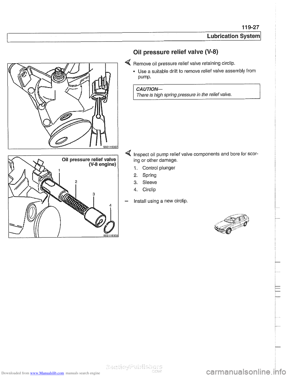
4 Remove oil pressure relief valve retaining circlip.
Use a suitable drift to remove relief valve assembly from
pump.
CAUTION--
There is high spring pressure in the relief valve.
4 Inspect oil pump relief valve components and bore lor scor-
ing or other damage.
1. Control plunger
2. Spring
3. Sleeve
4. Circlip
- Install using a new circlip.
Page 351 of 1002
Downloaded from www.Manualslib.com manuals search engine
120-3
Ignition System
Warnings and cautions
The ignition system produces dangerous high voltage. In ad-
dition the sensitive electronic components can be damaged
if
proper precautions are not adhered to.
WARNING-
* Do not touch or disconnect any cables from the coils while
the engine is running or being
cranked by the starter.
The ignition system produces high voltages that can be
fatal. Avoid contact with exposed terminals. Use ex-
treme caution when working on a car with the ignition
switched on or the engine running.
- Connect and disconnect tlie DME system wiring and
test equipment leads only when the ignition is
OFF:
Before operating the starter without starting the engine
(for example when
making a compression test) always
disable the ignition.
CA
U TIOW-
Do not attempt to disable the ignition by removing the coils
from the spark plugs.
Connect or disconnect ignition system wires, multiple
wire connectors, and ignition test equipment leads only
while the ignition is
off Switch multimeter functions or
measurement ranges only with the test probes discon-
nected.
* Do not disconnect the battery while the engine is run-
ning.
A high impedance digital multimeter should be used for
all voltage and resistance tests. An LED test light
should be used in place of an incandescent-type test
lamp.
In general, make test connections only as specified by
BMW as described in this manual, or as described by
the instrument manufacturer.
Engine management
BMW €39 engines use an advanced engine management
system known as Digital Motor Electronics (DME). DME in-
corporates on-board diagnostics, fuel injection, ignition and
other engine control functions. DME variants are listed in
Table a. Engine management systems.
Second generation On-Board Diagnostics
(OED II) is incor-
porated into the engine management systems used on the
cars covered by this manual. Use a BMW-specific electronic
scan tool, or a "Generic"
OED II scan tool to access Diagnos-
tic Trouble Codes (DTCs). DTCs can help pinpoint ignition
ine management problems.
Page 352 of 1002
Downloaded from www.Manualslib.com manuals search engine
I lgnition System
Additional information about DTCs and engine management
system electronic system diagnosis is provided in
OBD On-
Board Diagnostics.
Table a. Engine management systems
Year
l~ngine I Engine type IDME svstem I - I - . . I
Ignition system
1997-1 998
1997
1998
1999-2002
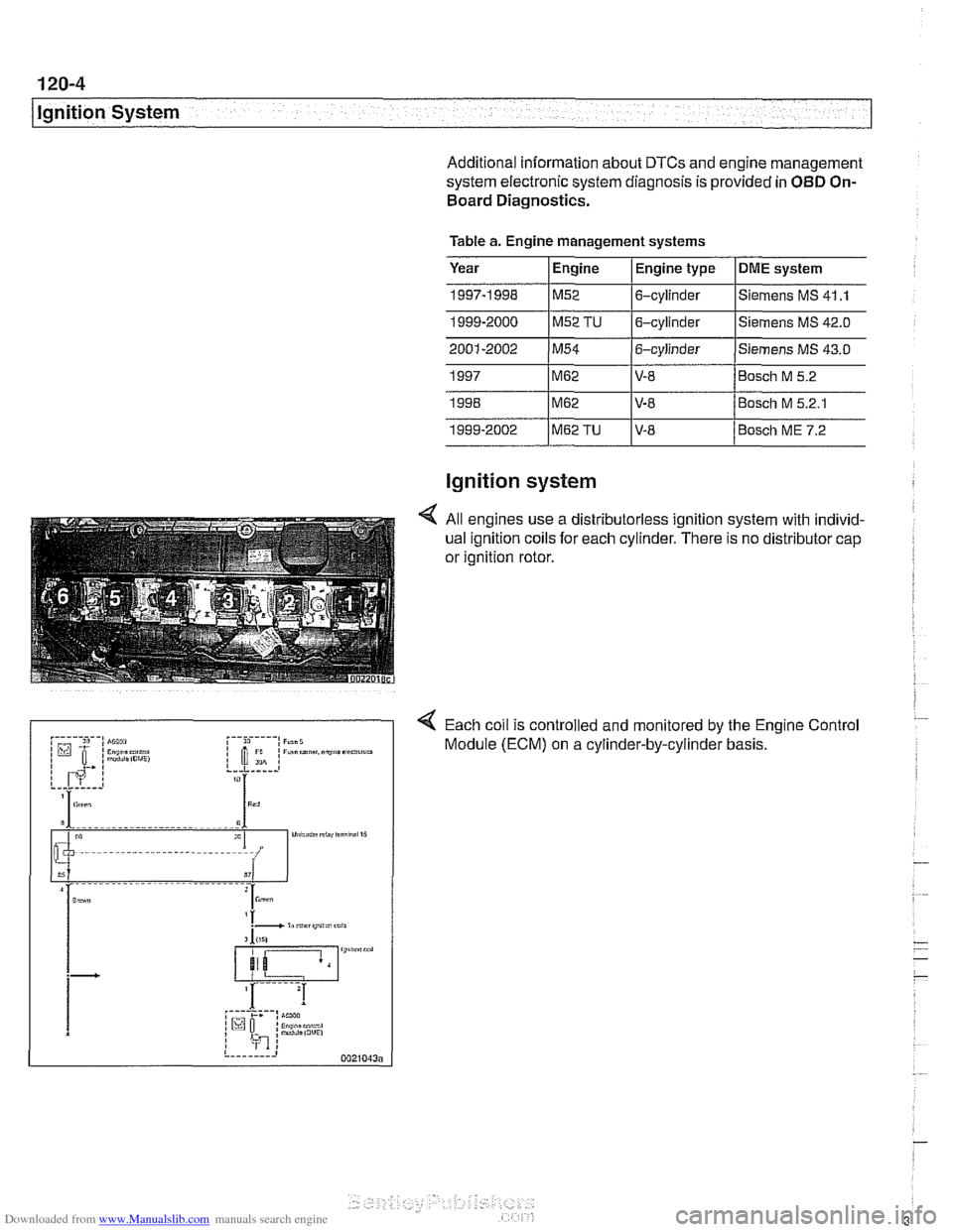
4 All engines use a distributorless ignition system with individ-
ual ignition coils for each cylinder. There is no distributor cap
or ignition rotor.
4 Each coil is controlled and monitored by the Engine Control
Module (ECM) on a cylinder-by-cylinder basis.
1999-2000
1~52 TU 16-cylinder l~iemens MS
42.0
M62
M62
M62TU
Siemens MS 41 .I M52 6-cylinder
V-8
V-8 V-8 Bosch
M 5.2
Bosch M 5.2.1
Bosch ME 7.2
Page 353 of 1002
Downloaded from www.Manualslib.com manuals search engine
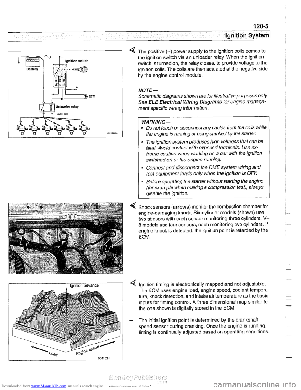
Lnition switch
4 The positive (+) power supply to the ignition coils comes to
the ignition switch via an unloader relay. When the ignition
switch is turned on, the relay closes, to provide voltage to the
ignition coils. The coils are then actuated at the negative side
by the engine control module.
NOTE-
Schematic diagrams shown are for illustrative purposes only.
See ELE Electrical Wiring Diagrams for engine manage-
ment specific wiring information.
WARNING- Do not touch or disconnect any cables from the coils while
the engine is running or being cranked by the starter:
The ignition system produces high voltages that can be
fatal. Avoid contact with exposed terminals. Use ex-
treme caution when
working on a car with the ignition
switched on or the engine running.
* Connect and disconnect the DME system wiring and
test equipment leads only when the ignition is
OFF
Before operating the starter without starting the engine
(for example when
making a compression test), always
disable the ignition.
4 Knock sensors (arrows) monitor the combustion chamber for
engine-damaging knock. Six-cylinder models (shown) use
two sensors with each sensor monitoring three cylinders.
V-
8 models use four sensors, each monitoring two cylinders. If
engine
knock is detected, the ignition point is retarded by the
ECM.
I Ignition advance Ignition timing is electronically mapped and not adjustable.
The ECM uses engine load, engine speed, coolant tempera-
ture, knock detection, and intake air temperature as the basic
inputs for timing control.
A three dimensional map similar to
the one shown is digitally stored in the ECM.
- The initial ignition point is determined by the crankshaft
speed sensor during cranking. Once the engine is running.
timing is continually adjusted based on operating conditions.
Page 359 of 1002
Downloaded from www.Manualslib.com manuals search engine
Ignition System
- Turn ignition on and check for battery voltage,
If battery voltage is not present,
checlt wire between termi-
nal
15 and the unloader relay. See ELE Electrical Wiring
Diagrams.
- Turn ignition off.
Remove coil and inspect coil housing for hairline
cracks or
leaking casting material. Replace any
cracked or leaking coil.
NOTE-
A leaky coil may indicate a faulty Engine Control Module
(ECM). Check ECM before installing a new coil.
CAUTION-
Note location of coilground straps before coil removal; rein-
stall in the same location.
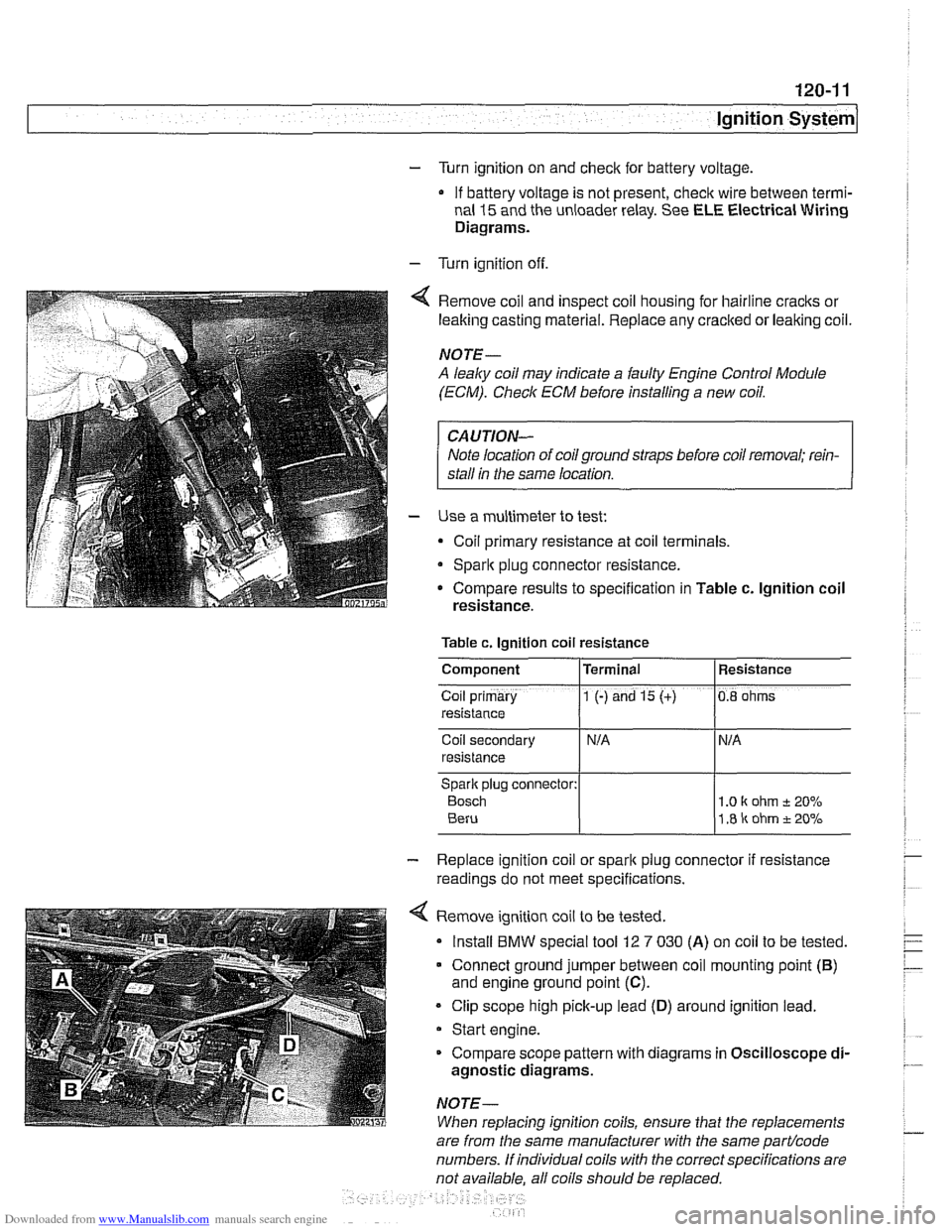
Use a multimeter to test:
Coil primary resistance at coil terminals.
Sparlt plug connector resistance.
* Compare results to specification in Table c. lgnition coil
resistance.
Table c. Ignition coil resistance
Coil secondary
resistance
Spark plug connector:
Bosch 1 .O I( ohm t 20%
1.8 ir ohm t 20%
Component
Co~l prlmary
resistance
- Replace ignition coil or sparlt plug connector if resistance
readings do not meet specifications.
4 Remove ignition coil to be tested.
Install
BMW special tool 12 7 030 (A) on coil to be tested.
Connect ground jumper between coil mounting point
(B)
and engine ground point (C).
Clip scope high pick-up lead (D) around ignition lead.
Start engine.
Compare scope pattern with diagrams in Oscilloscope
di-
agnostic diagrams.
NOTE-
When replacing ignition coils, ensure that the replacements
Terminal
1 (-) and 15 (+)
are
from the same manufacturer with the same partlcode
numbers. If individual coils with the correct specifications are
not available. all coils should be
re~laced.
Resistance
0.8 ohms