bolt BMW 528i 1999 E39 Workshop Manual
[x] Cancel search | Manufacturer: BMW, Model Year: 1999, Model line: 528i, Model: BMW 528i 1999 E39Pages: 1002
Page 614 of 1002
Downloaded from www.Manualslib.com manuals search engine
-.- .
/ Driveshaft Driveshaft, removing
CAUTION-
. Be sure the wheels are off the ground before removing the
driveshak Set the parl(ing brake before removing the
driveshaft.
Once the driveshaft has been removed, the vehicle can
roll regardless of whether the transmission is in gear or
not.
The driveshaft is mounted to the transmission and final
drive
with self-locliing nuts. These nuts are designed to
be used only once and should be replaced during reas-
sembly.
Remove complete exhaust system. See
180 Exhaust
System.
- Remove exhaust heat shields.
- Support transmission with transmission jack.
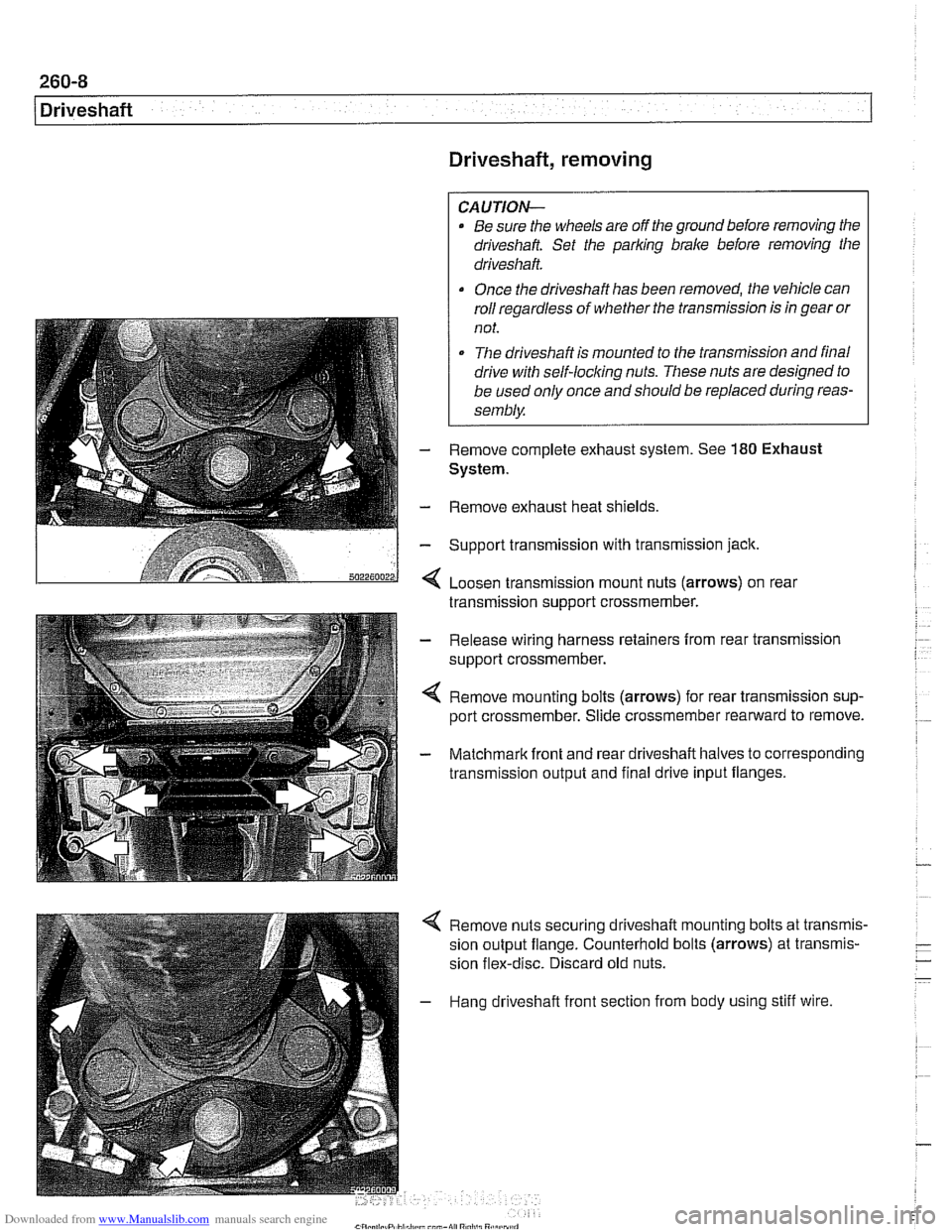
< Loosen transmission mount nuts (arrows) on real
transmission support crossmember.
- Release wiring harness retainers from rear transmission
support crossmember.
< Remove mounting bolts (arrows) for rear transmission sup-
port crossmember. Slide crossmember rearward to remove.
- Matchmark front and rear driveshaft halves to corresponding
transmission output and final drive input flanges.
4 Remove nuts securing driveshaft mounting bolts at transmis-
sion output flange. Counterhold bolts (arrows) at transmis-
sion flex-disc. Discard old nuts.
- Hang driveshaft front section from body using stiff wire.
Page 615 of 1002
Downloaded from www.Manualslib.com manuals search engine
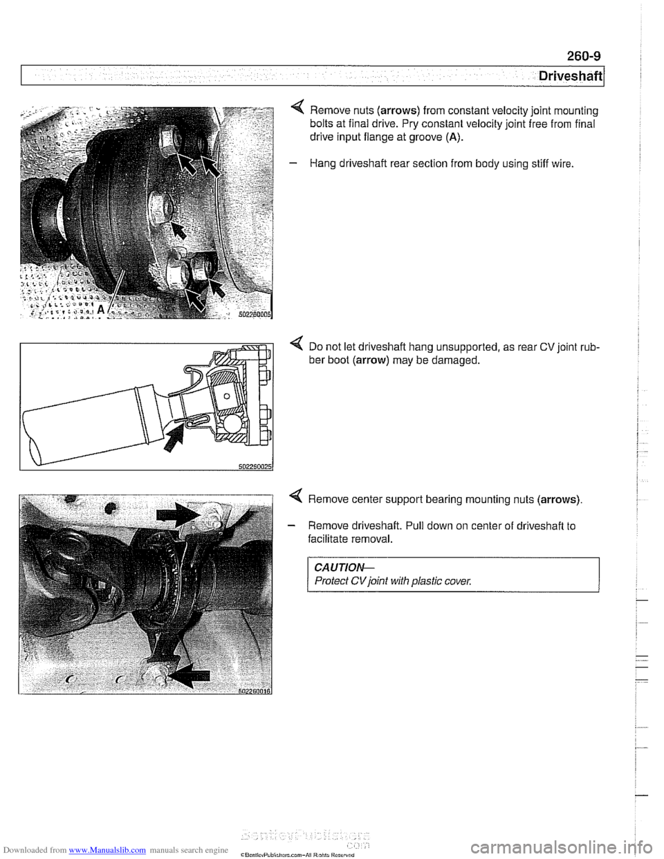
4 Remove nuts (arrows) from constant velocity joint mounting
bolts at final drive. Pry constant velocity joint free from final
drive input flange at groove
(A).
- Hang driveshaft rear section from body using stiff wire.
< Do not let driveshaft hang unsupported, as rear CV joint rub-
ber boot (arrow) may be damaged.
4 Remove center support bearing mounting nuts (arrows)
- Remove driveshaft. Pull down on center of driveshaft to
facilitate removal.
CAUTIOI\C
Protect CVjoint with plastic cover.
Page 616 of 1002
Downloaded from www.Manualslib.com manuals search engine
260-1 0
/ Driveshaft
Driveshaft, installing
- Prepare CV joint for reinstallation:
Extend joint to limit.
Clean off old grease and fill with fresh grease
Install new seal.
- Bend driveshaft slightly at center universal joint to install
CAUTION-
Do not allow CVjoint seal to become displaced.
- Align matchmarlts on driveshaft to matchmarks on final drive
and transmission flanges.
- Fit constant velocity joint to final drive input flange. Alternate-
ly tighten two opposite nuts to draw constant velocity joint
evenly into the final drive input flange. Once seated, tighten
down remaining nuts.
I CAUTION-
I Do not reuse self-locking nuts. These nuts are designed to be /
I used onlv once. 1
- Insert bolts in front of driveshafl to transmission output
flange. Counterhold each bolt while tightening nut.
CAUTION-
. Do not reuse self-locking nuts. These nuts are designed to
be used only once.
Avoid stressing the flex-disc when torquing the bolts.
Do this by counterholding the bolts and turning the nuts
on the flange side.
- Position center support bearing and install mounting nuts.
Use new self-locking nuts.
- Install heat shields.
- Install rear transmission support crossmember.
- Install exhaust system. See 180 Exhaust System.
Reconnect oxygen sensor wiring harnesses and reattach
wiring harness retainers to rear transmission support
crossrnernber.
Page 617 of 1002
Downloaded from www.Manualslib.com manuals search engine
Driveshaft
- Road test vehicle to check for noise or vibration
CAUTION-
Do not reuse self-locking nuts. These nuts are designed to
be used only once.
Avoid stressing the flex-disc when torquing the bolts.
Do this by counterholding the bolts and turning the nuts
on the flange side.
Tightening torques
Alunlinum driveshaft to flex-disc
- MI2 (use coated washers)
90 Nm (66 ft-lb)
Driveshaft
CV joint to final drive flange
Mi0 (Tom bolt)
70 Nm (51 ft-lb)
M8 (compression nut) 32 Nm (24 ft-lb)
Flex-disc to transmission flange or driveshaft
MI0 (8.8 grade) 48 Nm (35 ft-lb)
MI 0 (1 0.9 grade) 60 Nm (44 ft-lb)
- Mi2 (8.8 grade)
81 Nm (60 ft-lb)
- MI2 (10.9 grade) I00 Nm (74 ft-lb)
MI4 140 Nm (103 ft-lb)
Transmission
crossmember
to transmission (ME) 21 Nm (15 ft-lb)
. to chassis (M10) 42 Nm (30 ft-lb)
NOTE-
Boltgrade is marked on the bolt head. When replacing bolts,
only use bolts of the same strength and hardness as the orig-
inals installed.
Flex-disc, replacing
- Checlc flex-disc between front section of driveshafl and trans-
mission output flange for craclts, tears, missing pieces, or
distortion. Check for worn bolt hole bores in flange.
- If flex-disc needs replacement, remove driveshafl as de-
scribed earlier.
- Unbolt flex-disc from driveshaft.
NOTE-
Removal andinstallation of the bolts may be made easier by
placing a large hose clamp around the flex-disc, and tighten-
ing the clamp slightly to compress the rubber.
Page 618 of 1002
Downloaded from www.Manualslib.com manuals search engine
260-1 2
1 Driveshaft
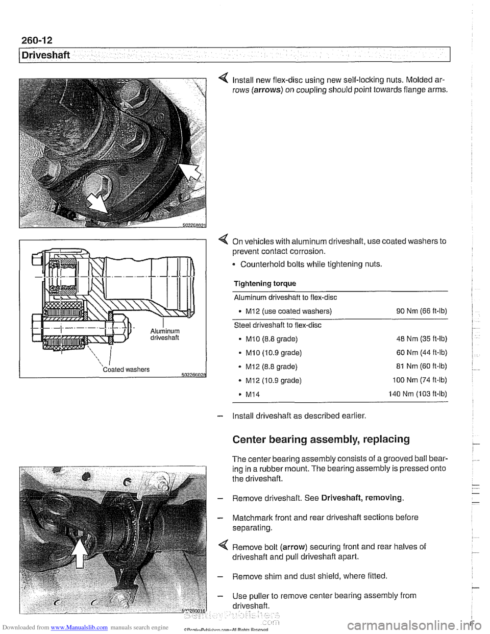
Install new flex-disc using new self-locking nuts. Molded ar-
rows (arrows) on coupling should point towards flange arms.
4 On vehicles with aluminum driveshaft, use coated washers to
prevent contact corrosion.
- Counterhold bolts while tightening nuts.
Tightening torque
Aluminum driveshaft to flex-disc
M12 (use coated washers) 90
Nm (66 ft-lb)
Steel driveshaft to flex-disc
MI0 (8.8 grade) 48
Nm (35 ft-lb)
- MI0 (10.9 grade) 60 Nm (44 ft-lb)
Coated washers - MI2 (8.8 grade) 5027500 . Mi2 (10.9 grade)
M14 81
Nm (60 ft-lb) 100 Nm (74 ft-lb)
140 Nm (103 ft-lb)
- Install driveshaft as described earlier
Center bearing assembly, replacing
The center bearing assembly consists of a grooved ball bear-
ing in a rubber mount. The bearing assembly is pressed
the driveshaft.
- Remove driveshaft. See Driveshaft, removing
- Matchmark front and rear driveshaft sections before
separating.
Remove bolt (arrow) securing front and rear halves of
driveshaft and pull driveshaft apart.
- Remove shim and dust shield, where fitted
- Use puller to remove center bearing assembly from
driveshaft. onto
Page 619 of 1002
Downloaded from www.Manualslib.com manuals search engine
- On installation, drive new center bearing firmly to stop.
Reassemble driveshaft using matchmarks made prior to
disassembly.
- Clean threads and install bolt securing driveshaft halves.
Use thread locking compound
LoctiteO or equivalent.
Tightening torque Driveshaft front half to rear half
(use thread locking compound) 97
Nm (72 fl-lb)
- Install driveshaft as described earlier.
Front centering guide, replacing
The front centering guide centers the driveshafl in relation to
the transmission. The guide is press-fit into a cavity in the
front of the driveshafl and slides onto the transmission output
shaft.
No specifications are given
forwear of the guide, but general-
ly the guide should fit snugly on the transmission output shafl.
NOTE-
Some driveshafts have a dust cap installed on the end of the
driveshaft, over the centering guide. The dust cap may be-
come bent or distorted when the driveshaft is removed or
in-
stalled. Damage to the dust cap should not affect the
centering guide and should not be mistaken for guide wear.
- Remove driveshafl as described earlier
- Pack cavity behind centering guide with heavy grease until
grease is flush with bottom edge of guide.
- Insert 14 mm (approximately 9/16 in.) diameter mandrel or
metal rod into guide. Strike guide with hammer to force cen-
tering guide out.
NOTE-
Tlie mandrel should fit snugly in the centering guide so that
the grease cannot escape around the sides of the mandrel.
- Remove old grease from driveshaft, lubricate new centering
guide with molybdenum disulfide grease
(MolykoteO, Long-
term8 2 or equivalent) and drive it into driveshaft.
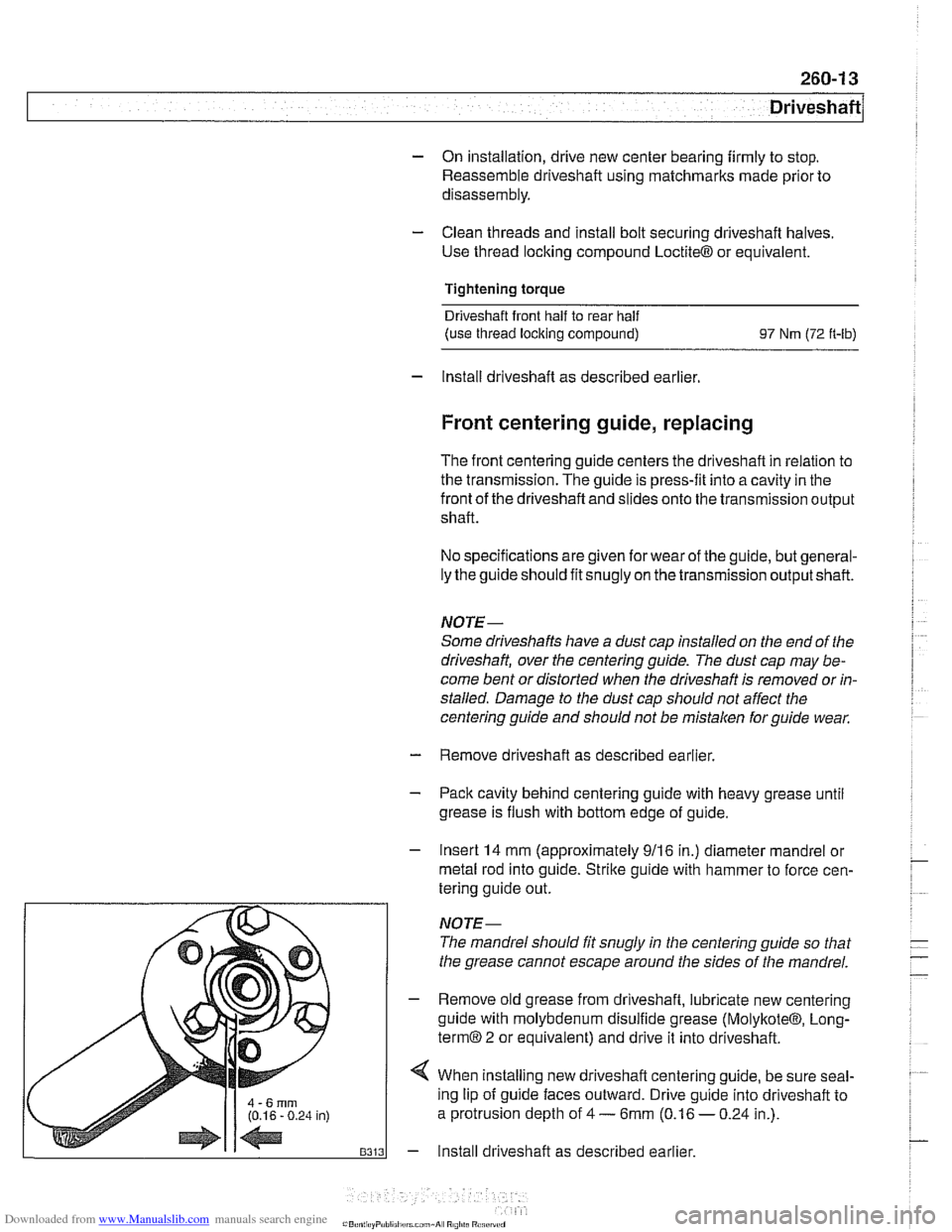
4 When installing new driveshafl centering guide, be sure seal-
ing lip of guide faces outward. Drive guide into driveshaft to
a protrusion depth of
4 - 6mm (0.16 - 0.24 in.).
- Install driveshaft as described earlier.
Page 620 of 1002
Downloaded from www.Manualslib.com manuals search engine
260-14
Driveshaft
Constant velocity (CV) joint, replacing
The CV joint at the rear of the driveshaft is available from
BMW as a separate part.
- Remove complete driveshaft as described earlier in this
section.
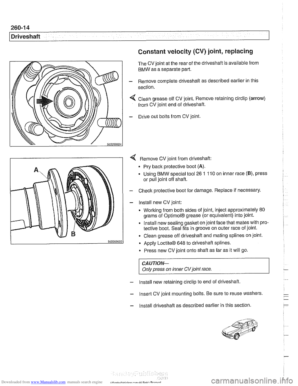
< Clean grease off CV joint. Remove retaining circlip (arrow)
from CV joint end of driveshaft.
- Drive out bolts from CV joint.
4 Remove CV joint from driveshaft:
Pry back protective boot
(A).
- Using BMW special tool 26 1 110 on inner race (B), press
or pull joint off shaft.
- Check protective boot for damage. Replace if necessary.
- lnstall new CV joint:
. Working from both sides of joint, inject approximately 80
grams of
OptimolB grease (or equivalent) into joint.
Install new sealing gasket on joint face that mates with pro-
tective boot. Seal fits in groove on outer race of joint.
Clean grease off driveshaft and mating splines on joint.
Apply
LoctiteO 648 to driveshaft splines.
Press new CV joint onto shaft as far as it will go.
CAUTIOI\C
Only press on inner CVjoint race.
- Install new retaining circlip to end of driveshaft,
- Insert CV joint mounting bolts. Be sure to reuse washers.
- Install driveshaft as described earlier in this section.
Page 622 of 1002
Downloaded from www.Manualslib.com manuals search engine
[~us~ension, Steering and Brakes - General
This section of the manual covers front and rear suspension,
braking and steering systems, and contains wheel, tire and
wheel alignment information and specifications. Also covered
here are the integrated braking and suspension systems in-
cluding
antilock braking (ABS), traction control (ASCIDSC),
and electronic height control (EHC).
Vehicle ride height information is at the end of this repair
group. Alignment information is in
320 Steering and Wheel
Alignment.
Aluminum suspension components
In order to reduce vehicle weight, aluminum suspension com-
ponents are used in some models. A test with a magnet will
easily reveal the metal used. If working with aluminum com-
ponents, be sure to read and follow the cautions below.
CAUTION-
* Due to the chemical and corrosion characteristics of alumi-
num, do not bring into contact with battery acid.
Do not use wire brushes with brass or iron bristles.
Only use brushes with stainless steel bristles.
Do not expose to flying sparks from
grinding/cutting op-
erations.
Do not subject to steel welding splashes.
Do not expose to temperatures over
80°C (176"F),
even for short periods. Temperatures in painting facili-
ties are not a problem.
The E39 front suspension subframe is used as a rigid mount-
ing platform for the front suspension arms, stabilizer bar and
steering gear.
The suspension arms, known as the lower control arms and
the tension struts (thrust arms), are connected to the
sub-
frame through rubber bushings. The arms are connected to
the steering
knucltles in a double pivot configuration.
Each front strut assembly includes a tubular strut and a coil
spring. The upper strut mount includes a bearing. The lower
end of each strut housing is fitted to the steering knuckle. The
integral wheel bearing and hub are bolted to the steering
Iknucltle.
6-cylinder and V-8 models use different steering systems and
other front suspension components.
Page 625 of 1002
Downloaded from www.Manualslib.com manuals search engine
300-5
Suspension, Steering and Brakes - ~enerall
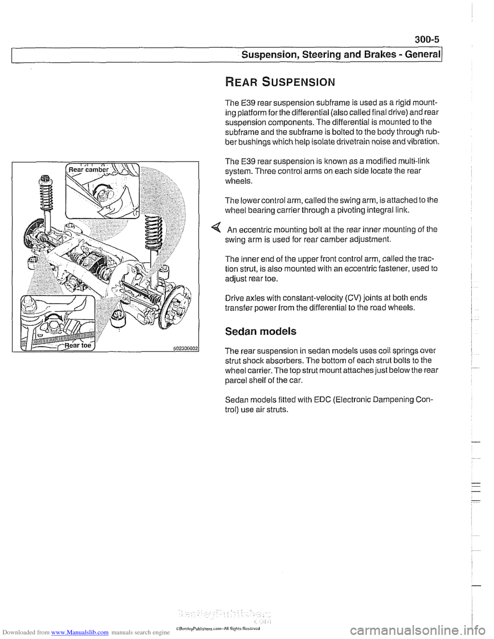
The E39 rear suspension subframe is used as a rigid mount-
ing platform
forthe differential (also called final drive) and rear
suspension components. The differential is mounted to the
subframe and the subframe is bolted to the body through rub-
ber bushings which help isolate drivetrain noise and vibration.
The
€39 rear suspension is known as a modified multi-link
system. Three control arms on each side locate the rear
wheels.
The lowercontrol arm, called the swing arm, is attached to the
wheel bearing carrier through a pivoting integral link.
An eccentric mounting bolt at the rear inner mounting of the
swing arm is used for rear camber adjustment.
The inner end of the upper front control arm, called the trac-
tion strut, is also mounted with an eccentric fastener, used to
adjust rear toe.
Drive axles with constant-velocity (CV) joints at both ends
transfer power
from the differential to the road wheels.
Sedan models
The rear suspension in sedan models uses coil springs over
strut shock absorbers. The bottom of each strut bolts to the
wheel
carrier.The top strut mount attaches just below the rear
parcel shelf of the car.
Sedan models fitted with EDC (Electronic Dampening Con-
trol) use air struts.
Page 641 of 1002
Downloaded from www.Manualslib.com manuals search engine
31 0-5
Front ~uspensionl
Front strut assembly, removing and
installing
- Raise car and remove front wheel.
WARNING-
Make sure that the car is firmly supported on jack stands de-
signed for the purpose. Place jack stands underneath struc-
tural chassis points.
Do not place jack stands under
suspension
parts.
- Unbolt bralte caliper assembly, lkeeping bralte hose connect-
ed. Secure brake caliper to body with wire. Do not let it hang
from brake hose. See
340 Brakes.
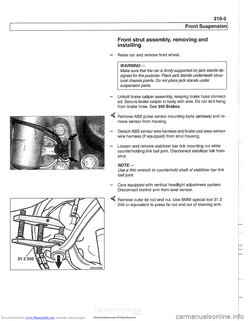
Remove ABS pulse sensor mounting bolts (arrows) and re-
move sensor from housing.
Detach ABS sensor wire harness and bralte pad wear sensor
wire harness (if equipped) from strut housing.
Loosen and remove stabilizer bar link mounting nut while
counterholding
link ball joint. Disconnect stabilizer link from
strut.
NOTE-
Use a thin wrench to counterhold shaft of stabilizer bar link
ball joint.
- Cars equipped with vertical headlight adjustment system:
Disconnect control arm from level sensor.
4 Remove outer tie rod end nut. Use BMW special tool 31 2
240 or equivalent to press tie rod end out of steering arm.