bolt BMW 528i 1999 E39 Workshop Manual
[x] Cancel search | Manufacturer: BMW, Model Year: 1999, Model line: 528i, Model: BMW 528i 1999 E39Pages: 1002
Page 592 of 1002
Downloaded from www.Manualslib.com manuals search engine
Automatic Transmission
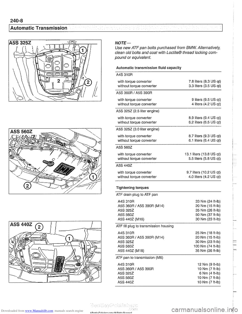
NOTE-
Use new ATF pan bolts purchased from BMW Alternatively,
clean old bolts and coat with
LoctiteB thread locl
Automatic transmission fluid capacity
with torque converter
7.8 liters (8.3 US qt)
without torque converter
3.3 liters (3.5 US qt)
A5S 360R 1 A5S 390R
with torque converter
without torque converter 9 liters (9.5 US qt)
4 liters (4.2 US qt)
A5S 3252 (2.5 liter engine)
with torque converter
without torque converter
8.9 liters (9.4 US qt)
6.2 liters (6.5 US qt)
A5S 3252 (3.0 liter engine)
with torque converter
8.7 liters (9.3 US qt)
without torque converter
6.1 liters (6.4 US qt)
A5S 5602
with torque converter 13.1 liters (13.8 US qt)
without torque converter
5.5 liters (5.8 US qt)
A5S 4402
with torque converter
without torque converter 9.7 liters (10.2 US qt)
4.0 liters (4.2 US qt)
Tightening torques
ATF drain plug to ATF pan
A4S 310R 33 Nm (24 ft-lb)
A5S 360R I A5S 390R (M14) 20 Nm (15 It-lb)
A5S
3252 35 Nm (26 ft-lb)
A5S 560Z 50 Nm (37 ft-lb)
A5S
4402 (MI 6) 30 Nm (23 ft-lb)
ATF fill plug
to transmission housing
A4S 31 OR 25 Nm (I8 ft-lb)
A5S 360R 1 A5S 390R (M14) 20 Nm (1 5 ft-lb)
A5S 3252 30 Nm (23 ft-ib)
A5S 5602 100 Nm (74 ft-lb)
A5S 4402 (M18) 35 Nm (26 ft-lb)
ATF pan to transmission (M6)
A4S 310R
A5S
360R 1 A5S 390R
A5S 3252
A5S
5602
A5S 4402
12 Nm (9 ft-lb)
10 Nm (7 ft-ib)
6 Nm (4 ft-lb)
10 Nm (7 ft-lb)
10 Nm (7 ft-lb)
Page 594 of 1002
Downloaded from www.Manualslib.com manuals search engine
240-1 0
Automatic Transmission
TRANSMISSION REMOVAL AND
INSTALLATION
Removal and installation of the transmission is best accorn-
plished on an automotive lift using a transmission jack. Use
caution and safe workshop practices when working beneath
car and lowering transmission.
Torx-head bolts are used to mount the transmission to the
bellhousing.
Besure to have appropriate tools on hand before
starting the job.
WARNING-
Be sure the vehicle is properly supported. The removal of the
transmission may upset the balance of the vehicle on a lift
CAUJION-
Tilting the engine to remove the transmission can lead to
damaae to various components due to
laclc of clearance. 1
Transmission, removing and installing
WARNING -
Allow engine and transmission to cool down before starting
work on the transmission.
- Disconnect negative (-) cable from battery.
CAUTION-
Prior to disconnecting the battery, read the battery discon-
nection cautions given in
001 General Cautions and
Warninas.
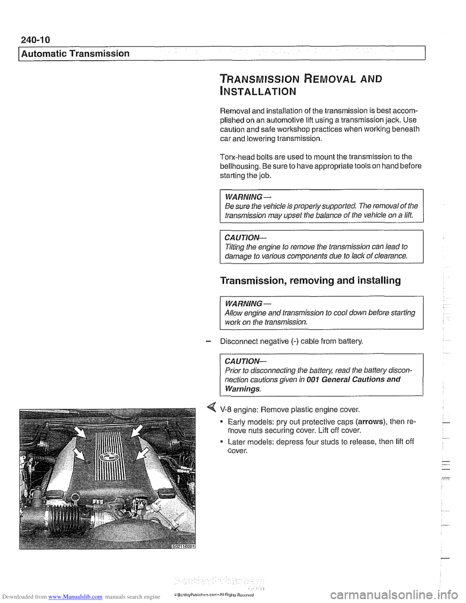
4 V-8 engine: Remove plastic engine cover.
Early models: pry out protective caps
(arrows), then re-
move nuts securing cover.
Lift off cover.
Later models: depress four studs to release, then lift off
cover.
Page 595 of 1002
Downloaded from www.Manualslib.com manuals search engine
Automatic ~ransmissionl
II I
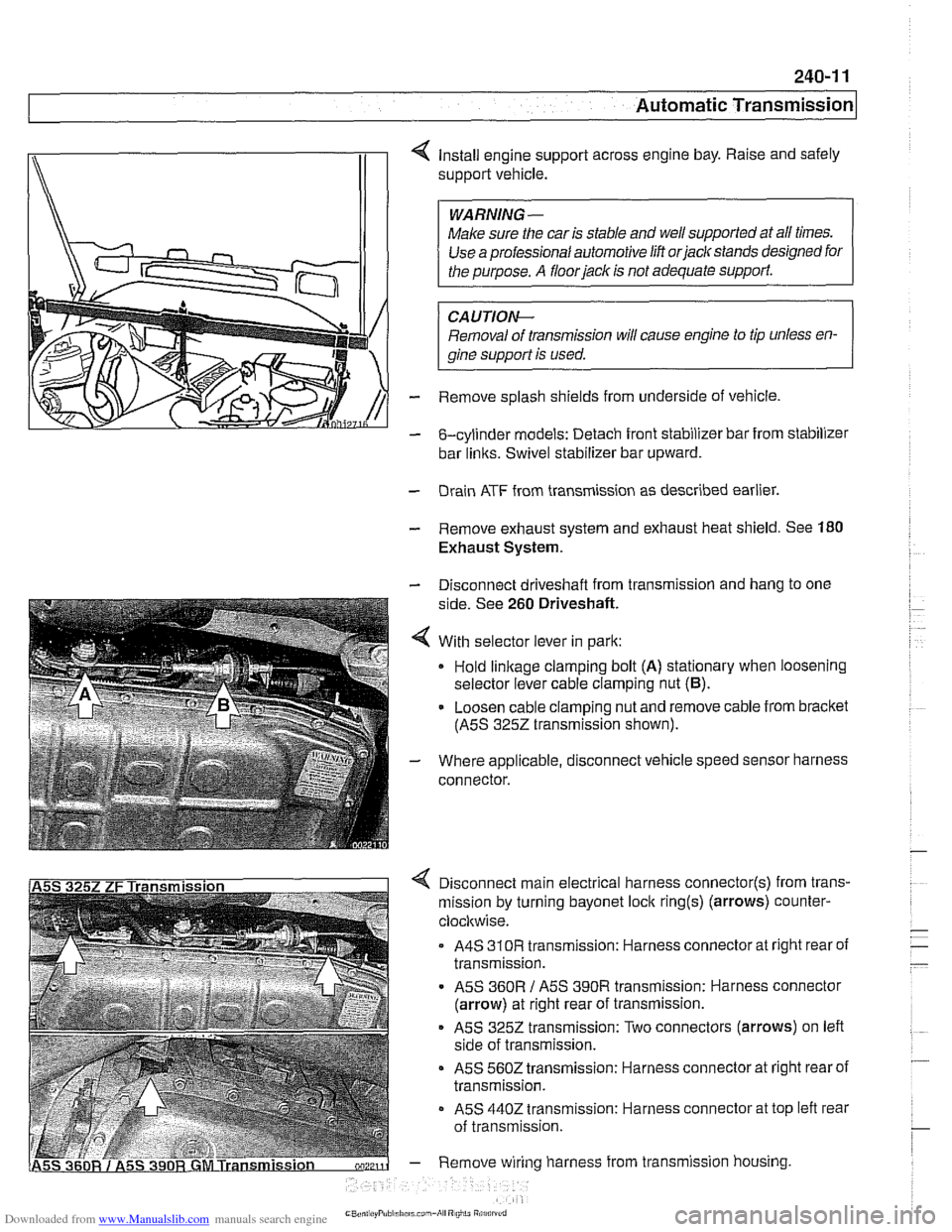
4 Install engine support across engine bay. Raise and safely
support vehicle.
Make sure the car is stable and
we1 supported at all times.
Use a professional automotive lift
orjaclc stands designed for
CAUTIOI\C
Removal of transmission will cause engine to tip unless en-
gine support is used.
- Remove splash shields from underside of vehicle.
- &cylinder models: Detach front stabilizer bar from stabilizer
bar
links. Swivel stabilizer bar upward.
- Drain ATF from transmission as described earlier.
- Remove exhaust system and exhaust heat shield. See 180
Exhaust System.
- Disconnect driveshaft from transmission and hang to one
side. See
260 Driveshaft.
4 With selector lever in park:
Hold
linkage clamping bolt (A) stationary when loosening
selector lever cable clamping nut
(6).
- Loosen cable clamping nut and remove cable from bracket
(ASS
3252 transmission shown).
- Where applicable, disconnect vehicle speed sensor harness
connector.
4 Disconnect main electrical harness connector(s) from trans-
mission by turning bayonet lock
ring(s) (arrows) counter-
clocltwise.
A4S
310R transmission: Harness connector at right rear of
transmission.
ASS
360R / ASS 390R transmission: Harness connector
(arrow) at right rear of transmission.
ASS 3252 transmission: Two connectors (arrows) on left
side of transmission.
ASS 5602 transmission: Harness connector at right rear of
transmission.
- ASS 4402 transmission: Harness connector at top left rear
of transmission.
- Remove wiring harness from transmission housing
Page 596 of 1002
Downloaded from www.Manualslib.com manuals search engine
Automatic Transmission
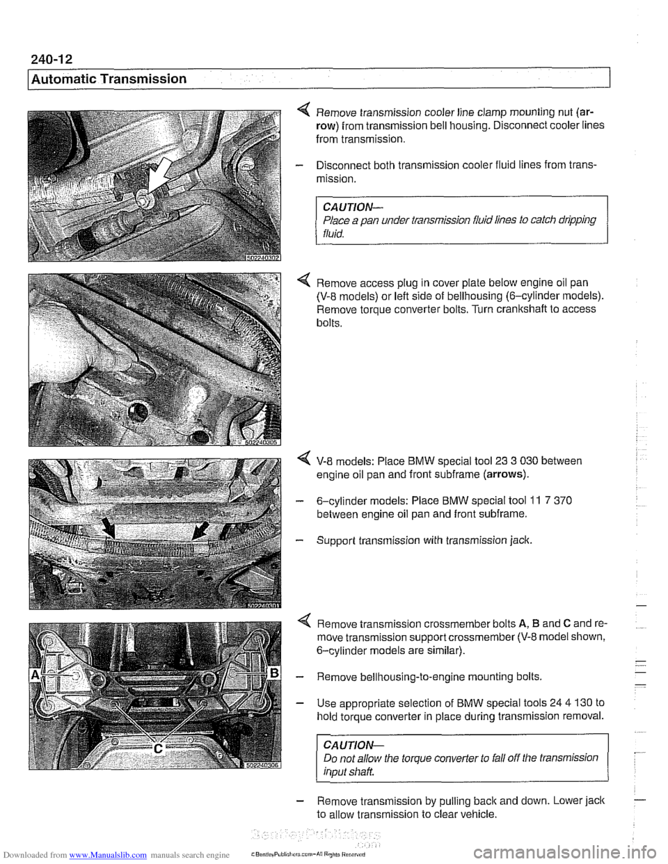
4 Remove transmission cooler line clamp mounting nut (ar-
row) from transmission bell housing. Disconnect cooler lines
from transmission.
- Disconnect both transmission cooler fluid lines from trans-
mission.
CAUTION-
Place a pan under transmission fluid lines to catch dripping
fluid.
4 Remove access plug in cover plate below engine oil pan
(V-8 models) or left side of bellhousing (6-cylinder models).
Remove torque converter bolts. Turn
cranltshaft to access
bolts.
V-8 models: Place BMW special tool 23 3 030 between
engine oil pan and front
subframe (arrows).
- 6-cylinder models: Place BMW special tool 11 7 370
between engine oil pan and front subframe.
- Support transmission with transmission jack.
4 Remove transmission crossmember bolts A, B and C and re-
move transmission support crossmember
(V-8 model shown,
6-cylinder models are similar).
- Remove bellhousing-to-engine mounting bolts.
- Use appropriate selection of BMW special tools 24 4 130 to
hold torque converter in place during transmission removal.
CAUTION-
Do not allow the torque converter to fall off the transmission
input shaft
- Remove transmlsslon by pull~ng back and down. Lower jack
to allow transmiss~on to clear vehicle.
rrs corn-hi8 Rniiti Riranrd
Page 597 of 1002
Downloaded from www.Manualslib.com manuals search engine
240-1 3
Automatic ~ransmissionl
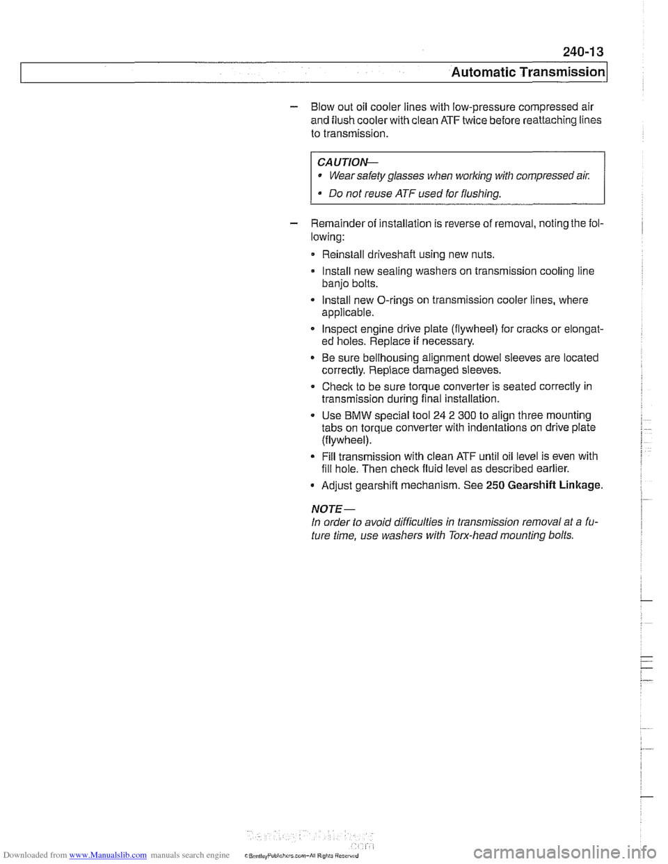
- Blow out oil cooler lines with low-pressure compressed air
and flush cooler with clean ATF twice before reattaching lines
to transmission.
CA UTIOG
Wear safety glasses when worling with compressed air:
@ Do not reuse ATF used for flushing.
- Remainder of installation is reverse of removal, noting the fol-
lowing:
Reinstall driveshafl using new nuts.
Install new sealing washers on transmission cooling line
banjo bolts.
Install new O-rings on transmission cooler lines, where
applicable.
Inspect engine drive plate (flywheel) for cracks or elongat-
ed holes. Replace
if necessary.
Be sure bellhousing alignment dowel sleeves are located
correctly. Replace damaged sleeves.
Checlc to be sure torque converter is seated correctly in
transmission during final installation.
Use
BMW special tool 24 2 300 to align three mounting
tabs on torque converter with indentations on drive plate
(flywheel).
Fill transmission with clean ATF until oil level is even with
fill hole. Then check fluid level as described earlier.
Adjust gearshift mechanism. See
250 Gearshift Linkage.
NOTE-
In order to avoid difficulties in transmission removal at a fu-
ture time, use washers with Torx-head mounting bolts.
Page 598 of 1002
Downloaded from www.Manualslib.com manuals search engine
. .
l~utomatic Transmission
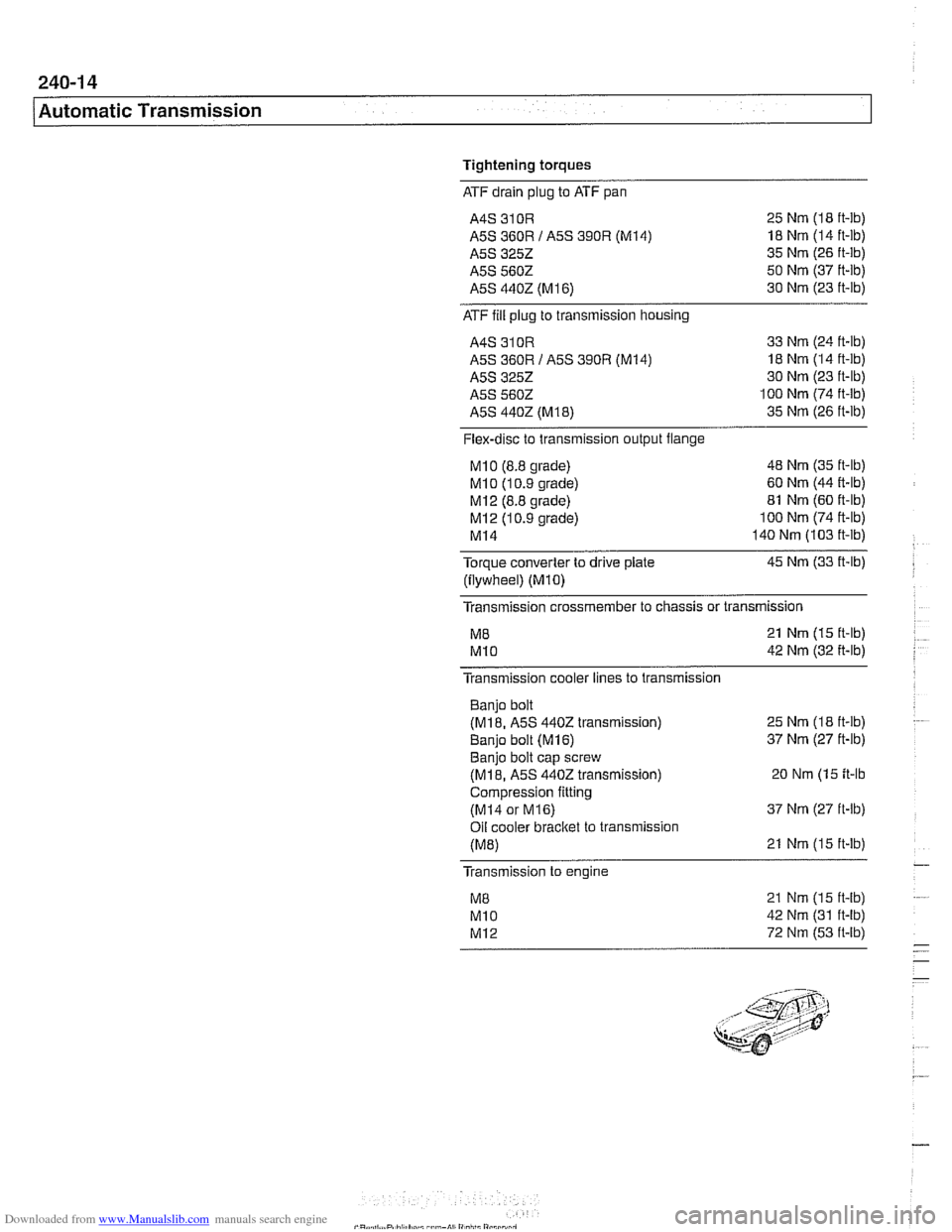
Tightening torques
ATF drain plug to ATF pan
A4S 310R 25 Nm (I8 ft-lb)
A5S 360R I A5S
390R (M14) 18 Nm (14 ft-lb)
A5S 3252 35 Nm (26 ft-lb)
A5S 5602 50 Nm (37 ft-lb)
A5S 4402 (M
16) 30 Nm (23 ft-lb)
ATF fill plug
to transmission housing
A4S 310R 33 Nm (24 ft-lb)
A5S 360R I A5S 390R (M14) 18 Nm (14 ft-lb)
A5S
3252 30 Nm (23 ft-lb)
A5S 5602 100 Nm (74 ft-lb)
A5S
4402 (M18) 35 Nm (26 ft-lb)
Flex-disc to transmission output flange
MI0 (8.8 grade) 48 Nm (35 it-lb)
MI 0 (1 0.9 grade) 60 Nm (44 R-lb)
MI2 (8.8 grade) 81 Nm (60 ft-lb)
MI 2 (1 0.9 grade) 100 Nm (74 ft-lb)
MI4 140 Nm (103 it-lb)
Torque converter to drive plate 45 Nm (33 ft-lb)
(flywheel)
(MIO)
Transmission crossmember to chassis or transmission
M8 21 Nm (15 ft-lb)
MI0 42 Nm (32 it-lb)
Transmission cooler lines to transmission
Banjo bolt
(M18. A5S 4402 transmission)
Banio bolt
(M16)
25 Nm (18 ft-lb)
37 Nm (27 ft-lb) . . Banjo bolt cap screw
(M18, A5S 4402 transmission) 20 Nm (15 it-lb
Compression fitting
(MI4 or M16) 37 Nm (27 ft-lb)
Oil cooler
bracket to transmission
(M8) 21 Nm (15 ft-lb)
Transmission to engine
21 Nm (15 ft-lb)
42 Nm (31 ft-lb)
72 Nm (53 ft-lb)
Page 603 of 1002
Downloaded from www.Manualslib.com manuals search engine
Gearshift Linkage
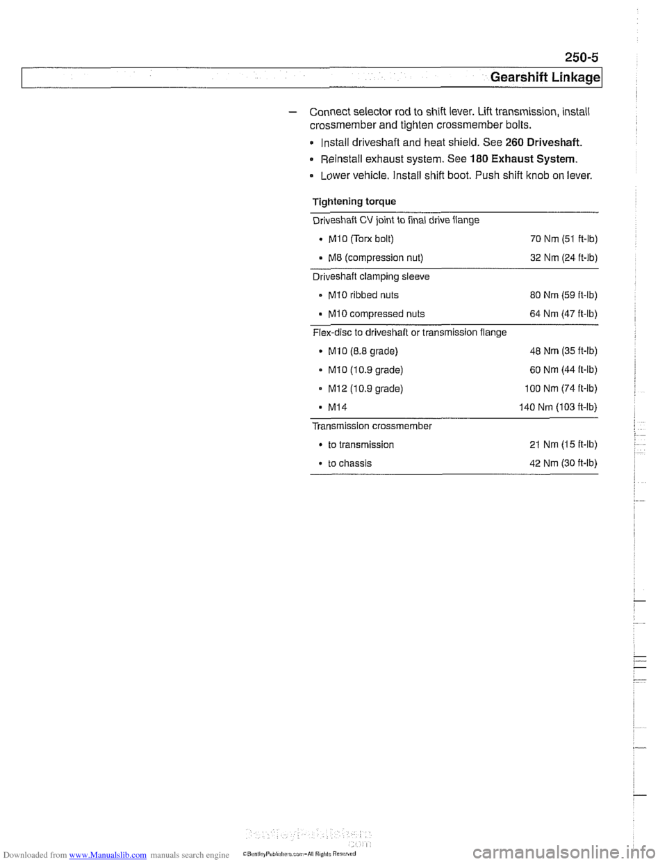
- Connect selector rod to shift lever. Lift transmission, install
crossmember and tighten crossmember bolts.
Install driveshaft and heat shield. See
260 Driveshaft.
Reinstall exhaust system. See 180 Exhaust System.
. Lower vehicle. Install shift boot. Push shift ltnob on lever.
Tightening torque
Driveshaft
CV joint to final drive flange
. MI0 (Tom bolt)
70 Nm (51 ft-lb)
. M8 (compression nut) 32 Nm (24 ft-lb) - Driveshaft clamping sleeve
- MI0 ribbed nuts
80 Nm (59 ft-lb)
MI0 compressed nuts 64 Nm (47 ft-lb)
Flex-disc to driveshaft or transmission flange
MlO (8.8 grade) 48
Nm (35 ft-lb)
. MI0 (10.9 grade) 60
Nm (44 ft-lb)
- MI2 (10.9 grade) 100 Nm (74 ft-ib)
MI4 140 Nm (103 fi-lb)
Transmission crossmember
. to transmission 21 Nm (15 ft-lb)
. to chassis 42 Nm (30 ft-lb)
Page 610 of 1002
Downloaded from www.Manualslib.com manuals search engine
1 Driveshaft
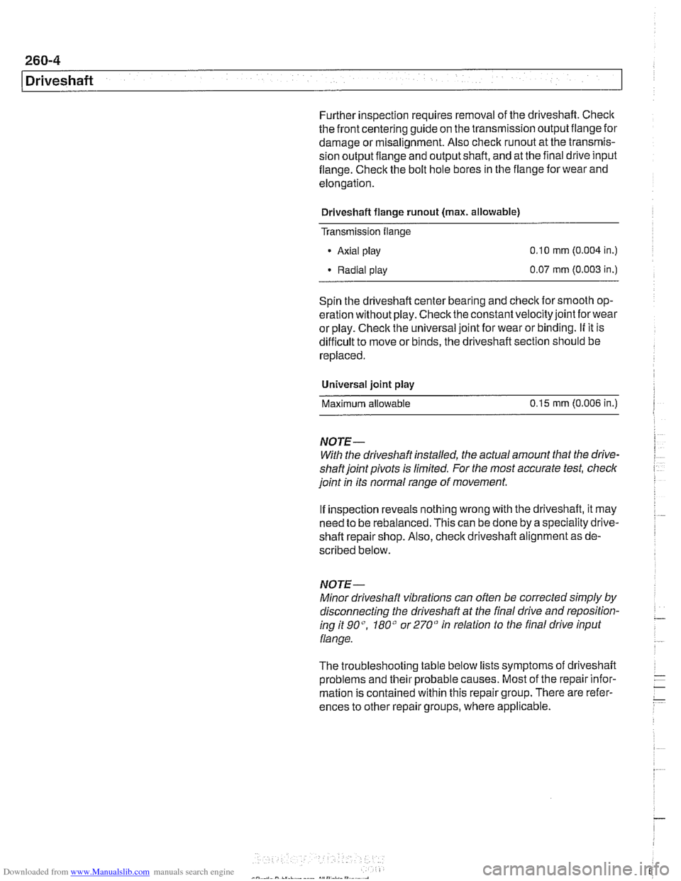
Further inspection requires removal of the driveshaft. Checlc
the front centering guide on the transmission output flange for
damage or
misalignment. Also check runout at the transmis-
sion output fiange and output shaft, and at the final drive input
fiange. Check the bolt hole bores in the flange for wear and
elongation.
Driveshaft flange
runout (max. allowable)
Transmission
flange
- Axial play 0.10 mm (0.004 in.)
Radial play 0.07
mm (0.003 in.)
Spin the driveshaft center bearing and
check ior smooth op-
eration without play. Check the constant velocity joint
forwear
or play. Checlc the universal joint for wear or binding. If it is
difficult to move or binds, the driveshaft section should be
replaced.
Universal joint
play
Maximum allowable 0.15
mm (0.006 in.)
NOTE-
With the driveshaft installed, the actual amount that the drive-
shaftjoint pivots is limited. For the most accurate test, check
joint
in its normal range of movement.
If inspection reveals nothing wrong with the driveshaft, it may
need to be rebalanced. This can be done by a speciality drive-
shaft repair shop. Also,
checlc driveshaft alignment as de-
scribed below.
NOTE-
Minor driveshaft vibrations can often be corrected simply by
disconnecting the driveshaft at the final drive and reposition-
ing it go", 180" or 270" in relation to the final drive input
flange.
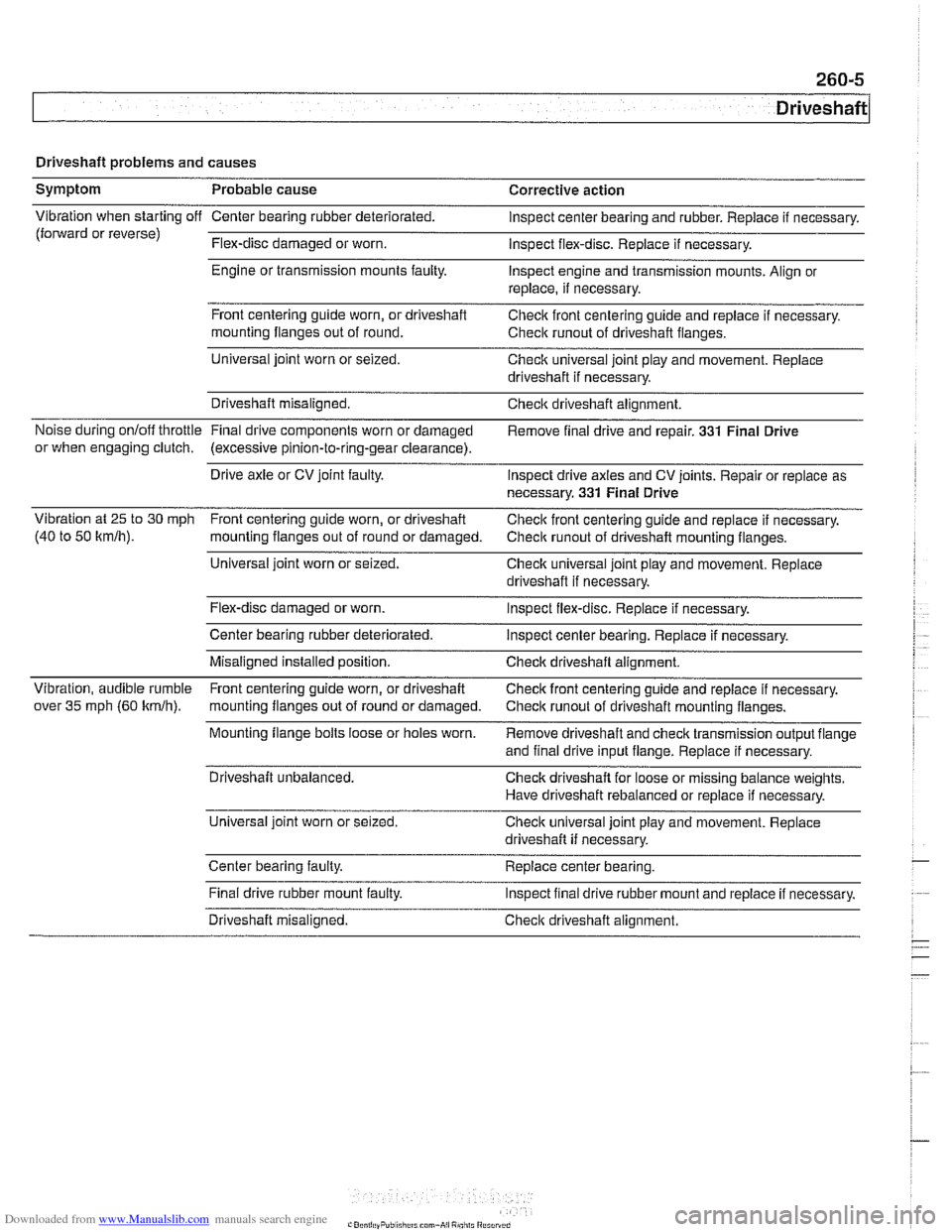
The troubleshooting table below lists symptoms
oi driveshaft
problems and their probable causes. Most of the repair infor-
mation is contained within this repair group. There are refer-
ences to other repair groups, where applicable.
Page 611 of 1002
Downloaded from www.Manualslib.com manuals search engine
Driveshaft
Driveshaft problems and causes
Symptom Probable cause Corrective action
Vibration when starting off Center bearing rubber deteriorated. Inspect center bearing and rubber. Replace if necessary.
(forward or reverse)
Flex-disc damaged or worn.
Inspect flex-disc. Replace
if necessary.
Engine or transmission mounts
faulty. Inspect engine and transmission mounts. Align or
replace, if necessary.
Front centering guide worn, or driveshaft
Checic front centering guide and replace
if necessary.
mounting flanges out of round.
Check
runout of driveshaft flanges.
Universal joint worn or seized.
Check universal joint play and movement. Replace
driveshaft if necessary.
Driveshaft misaligned. Check driveshaft alignment.
Noise during onloff throttle Final
drive components worn or damaged
Remove final drive and repair. 331 Final Drive
or when engaging clutch. (excessive pinion-to-ring-gear clearance).
Drive axle or CV joint faulty.
Inspect drive axles and CV joints. Repair or replace as
necessary.
331 Final Drive
Vibration at 25 to
30 mph
Front centering guide worn, or driveshaft
Check front centering guide and replace if necessary.
(40 to 50
kmlh). mounting flanges out of round or damaged.
Check runout of driveshaft mounting flanges.
Universal joint worn or seized.
Check universal joint play and movement. Replace
driveshaft if necessary.
Flex-disc damaged or worn.
Inspect flex-disc. Replace if necessary.
Center bearing rubber deteriorated.
Inspect center bearing. Replace if necessary.
Misaligned installed position. Check driveshaft alignment.
Vibration, audible rumble Front centering guide worn, or driveshaft
Check front centering guide and replace
if necessary.
over
35 mph (60 kmlh). mounting flanges out of rouncl or damaged.
Check runout of driveshaft mounting flanges. - -
Mounting flange bolts loose or holes worn.
Remove driveshaft and check transmission output flange
and final drive input flange. Replace if necessary.
Driveshaft unbalanced. Check driveshaft for loose or missing balance weights.
Have driveshaft rebalanced or replace if necessary.
Universal ioint worn or seized.
Check universal ioint
~lav and movement. Reolace ' .. driveshaft if necessary.
Center bearing faulty.
Replace center bearing.
.
Final drive rubber mount faulty.
Inspect final drive rubber mount and repiace if necessary.
Driveshaft misaligned.
Check driveshaft alignment.
Page 612 of 1002
Downloaded from www.Manualslib.com manuals search engine
Driveshaft
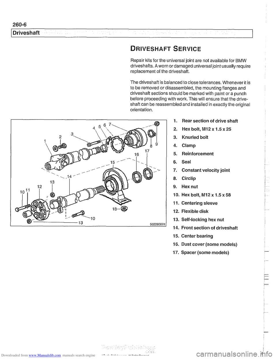
Repair kits for the universal joint are not available for BMW
driveshafts.
A worn or damaged universal joint usually require
replacement of the driveshaft.
The driveshaft is balanced to close tolerances. Whenever it is
to be removed or disassembled, the mounting flanges and
driveshaft sections should be marked with paint or a punch
before proceeding with work. This will ensure that the
drive-
shaft can be reassembled and installed in exactly the original
orientation.
1. Rear section of drive shaft
2. Hex bolt, MI2 x 1.5 x 25
3. Knurled bolt
4. Clamp
5. Reinforcement
6. Seal
7. Constant velocity joint
8. Circlip
9. Hex nut
10. Hex bolt, M12x 1.5~58
11. Centering sleeve
12. Flexible disk
13. Self-locking hex nut
14. Front section of driveshaft
15. Center bearing
16. Dust cover (some models)
17. Spacer (some models) -