bolt BMW 528i 1999 E39 Workshop Manual
[x] Cancel search | Manufacturer: BMW, Model Year: 1999, Model line: 528i, Model: BMW 528i 1999 E39Pages: 1002
Page 526 of 1002
Downloaded from www.Manualslib.com manuals search engine
/Exhaust System Muffler, replacing
BMW offers individual mufflers as replacement parts for the
original one-piece assembly. Replacement of a rear muffler
may be possible with the system installed on the car. Re-
placement of the front or middle muffler should only be done
with the exhaust removed from the car.
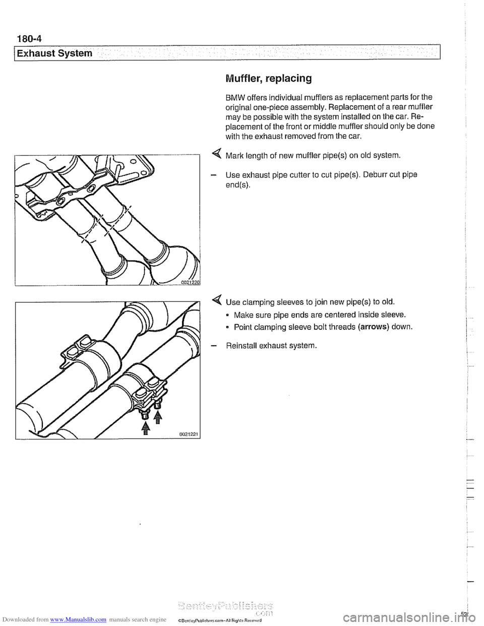
< Mark length of new muffler pipe(s) on old system.
- Use exhaust pipe cutter to cut pipe(s). Deburr cut pipe
end@).
4 Use clamping sleeves to join new pipe(s) to old.
Make sure pipe ends are centered inside sleeve.
Point clamping sleeve bolt threads
(arrows) down.
- Reinstall exhaust system.
Page 527 of 1002
Downloaded from www.Manualslib.com manuals search engine
Exhaust system1
Exhaust manifold removal procedures are organized accord-
ing to engine code. If necessary, see
100 Engine-General
for engine code and application information.
Exhaust manifolds, removing and installing
(M52 engine)
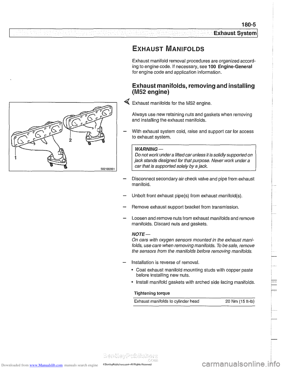
4 Exhaust manifolds for the M52 engine.
Always use new retaining nuts and gaskets when removing
and installing the exhaust manifolds.
- With exhaust system cold, raise and support car for access
to exhaust system.
WARNING -
Do not work under a lined car unless it is solidly supported on
jack stands designed for that purpose. Never work under a
car that is supported solely by a jack.
- Disconnect secondary air check valve and pipe from exhaust
manifold.
- Unbolt front exhaust pipe@) from exhaust rnanifold(s)
- Remove exhaust support bracket from transmission.
- Loosen and remove nuts from exhaust manifolds and remove
manifolds. Discard nuts and gaskets.
NOTE-
On cars with oxygen sensors mounted in the exhaust mani-
folds, use care when removing manifolds.
To be safe, remove
the sensors from the manifolds before removing manifolds.
- Installation is reverse of removal
Coat exhaust manifold mounting studs with copper paste
before installing new nuts.
Install manifold gaskets with arched side facing manifolds.
Tightening torque
Exhaust manifolds
to cylinder head 20 Nm (15 ft-lb)
Page 528 of 1002
Downloaded from www.Manualslib.com manuals search engine
180-6
Exhaust System
Exhaust manifolds, removing and installing
(M52 TU and M54 engines)
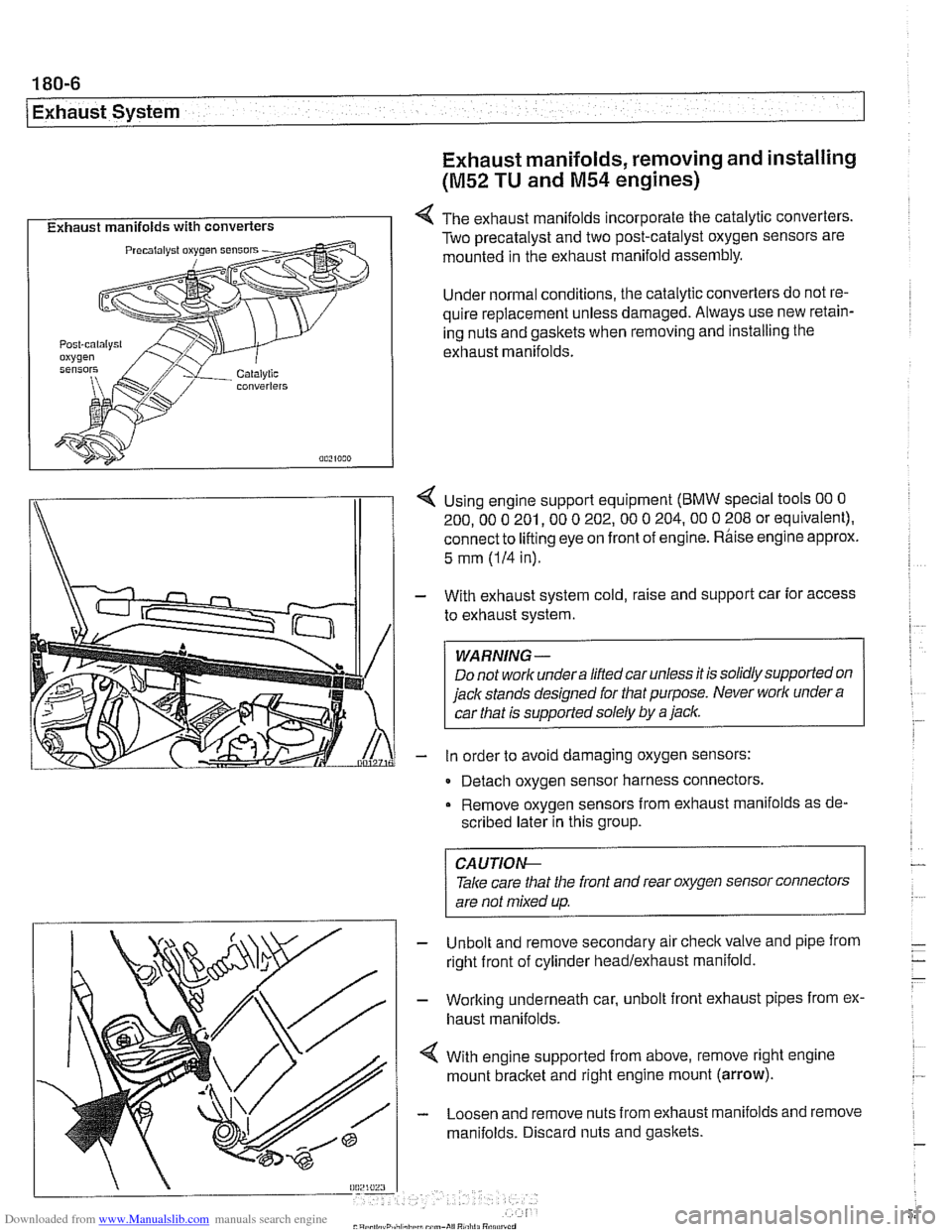
I Exhaust manifolds with converters I 4 The exhaust manifolds incorporate the catalytic converters.
Two precatalyst and two post-catalyst oxygen sensors are
mounted in the exhaust manifold assembly.
Under normal conditions, the catalytic converters do not re-
quire replacement unless damaged. Always use new retain-
ing nuts and gaskets when removing and installing the
exhaust manifolds.
I\
1 4 Using engine support equipment (BMW special tools 00 0
200. 00 0 201. 00 0 202.00 0 204.00 0 208 or equivalent).
connect to
lifting eye on front of engine. Rhise engine approx.
/I 1
5 mm (IH in).
With exhaust system cold, raise and support car for access
to exhaust system.
WARNING-
Do not worlc undera liftedcar unless it is solidly supported on
jack stands designed for that purpose. Never worlc under
a
car that is supported solely by a jaclc.
in order to avoid damaging oxygen sensors:
- Detach oxygen sensor harness connectors,
Remove oxygen sensors from exhaust manifolds as de-
scribed later in this group.
Unbolt and remove secondary air
checkvalve and pipe from
right front of cylinder headlexhaust manifold.
Working underneath car, unbolt front exhaust pipes from ex.
haust manifolds.
With engine supported from above, remove right engine
mount
bracket and right engine mount (arrow).
Loosen and remove nuts from exhaust manifolds and remove
manifolds. Discard nuts and gaskets.
CA UTIOG
Take care tliat the front and rear oxygen sensor connectors
are not mixed up.
-
Page 530 of 1002
Downloaded from www.Manualslib.com manuals search engine
- Removing left side exhaust manifolds (cylinder bank 5-8):
- Remove heat baffle plate on left side.
Remove oxygen sensor using
BMW special tool 11 7 030
or similar oxygen sensor socket.
Install
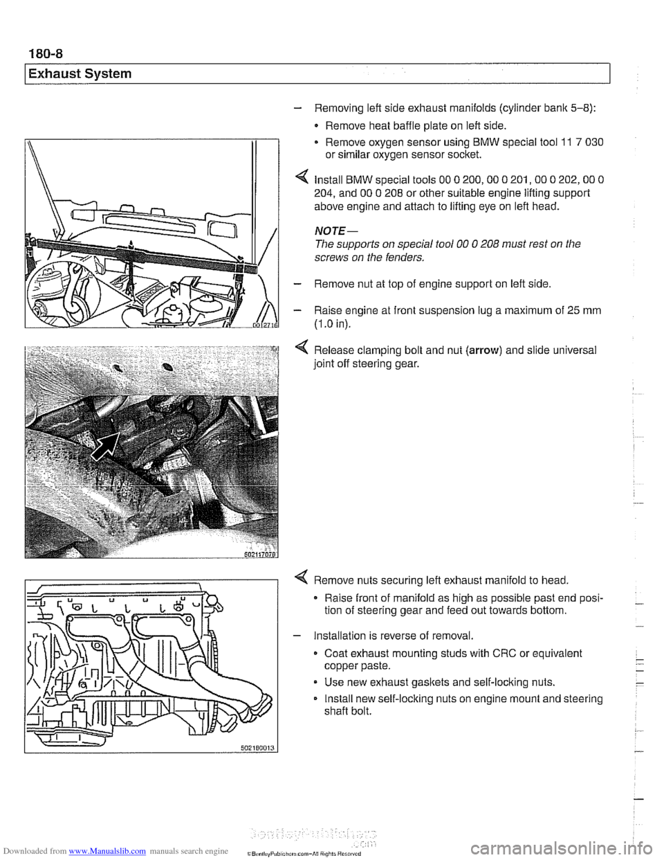
BMW special tools 00 0 200,OO 0 201,OO 0 202,OO 0
204, and 00 0 208 or other suitable engine lifting support
above engine and attach to lifting eye on left head.
NOTE-
The supports on special tool 00 0 208 must rest on the
screws on the fenders.
- Remove nut at top of engine support on left side
- Raise engine at front suspension lug a maximum of 25 mm
(I
.O in).
Release clamping bolt and nut
(arrow) and slide universal
joint off steering gear.
4 Remove nuts securing left exhaust manifold to head,
Raise front of manifold as high as possible past end posi-
tion of steering gear and feed out towards bottom.
- Installation is reverse of removal.
Coat exhaust mounting studs with CRC or equivalent
copper paste.
Use new exhaust gaskets and self-locking nuts.
Install new self-locking nuts on engine mount and steering
shaft bolt.
Page 540 of 1002
Downloaded from www.Manualslib.com manuals search engine
This repair group covers general application information for
the clutch, manual and automatic transmissions, shift linkag-
es and driveshaft.
Drivetrain
I ZF manual transmission I
BMW E39 models are equipped with a longitudinal drivetrain.
The transmission is bolted directly to the rear of the engine.
A
driveshaft connects the output shaft of the transmission to the
rear final drive. Individual drive axles with integrated constant
velocity joints transfer rotational power from the final drive
unit to the rear wheels.
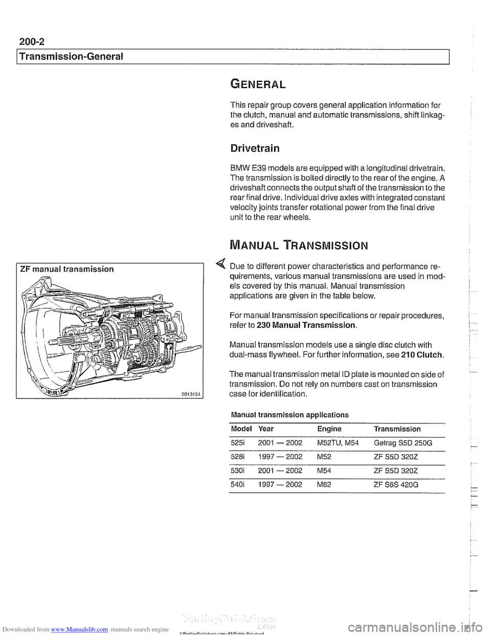
4 Due to different power characteristics and performance re-
quirements, various manual transmissions are used in mod-
els covered by this manual. Manual transmission
applications are given in the table below.
For manual transmission specifications or repair procedures,
refer to
230 Manual Transmission.
Manual transmission models use a single disc clutch with
dual-mass flywheel. For further information, see
210 Clutch.
The manual transmission metal ID plate is mounted on side of
transmission. Do not rely on numbers cast on transmission
case for identification.
Manual transmission applications
Model Year Engine Transmission
5251 2001 - 2002 M52TU, M54 Getrag S5D 250G
528i 1997-2002 M52 ZF S5D 3202
Page 545 of 1002
Downloaded from www.Manualslib.com manuals search engine
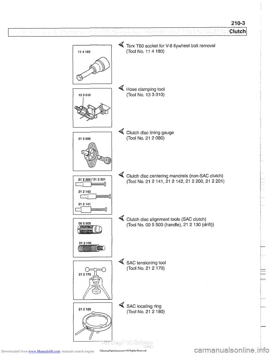
4 Tom T60 socket for V-8 flywheel bolt removal
(Tool No. 1 1 4 180)
4 Hose clamping tool
(Tool No. 13 3
01 0)
4 Clutch disc lining gauge
(Tool No. 21 2 080)
4 Clutch disc centering mandrels (non-SAC clutch)
(Tool No. 21 2
141,21 2 142,21 2 200,21 2 201)
4 Clutch disc alignment tools (SAC clutch)
(Tool No. 00 5 500 (handle). 21 2 130 (drift))
4 SAC tensioning tool
(Tool No. 21 2 170)
4 SAC locating ring
(Tool No. 21 2 180)
Page 549 of 1002
Downloaded from www.Manualslib.com manuals search engine
21 0-7
Clutch
- Remove brake fluid reservoir cap. Using a clean syringe.
remove brake fluid from reservoir to below level of clutch
hydraulic supply hose.
- Detach clutch hydraulic supply hose from brake fluid reser-
voir. Plug reservoir outlet and hose.
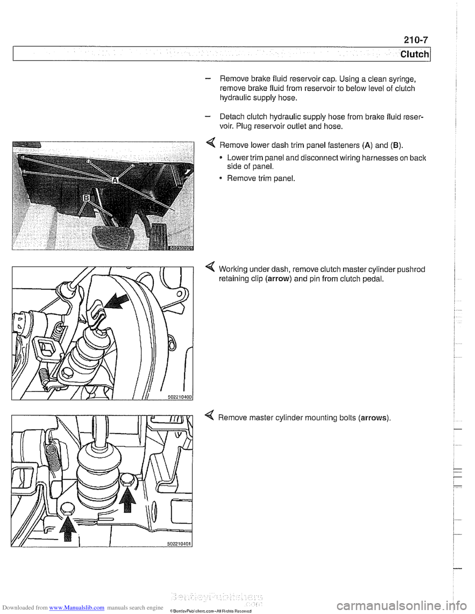
4 Remove lower dash trim panel fasteners (A) and (B).
Lower trim panel and disconnect wiring harnesses on back
side of panel.
Remove trim panel.
4 Working under dash, remove clutch master cylinder pushrod
retaining clip (arrow) and pin from clutch pedal.
4 Remove master cylinder mounting bolts (arrows)
Page 553 of 1002
Downloaded from www.Manualslib.com manuals search engine
Clutch, removing
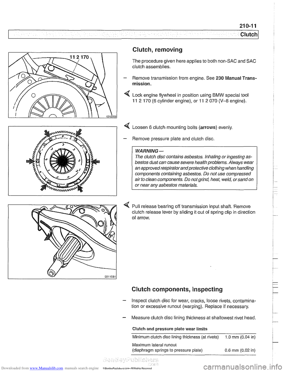
The procedure given here applies to both non-SAC and SAC
clutch assemblies.
- Remove transmission from engine. See 230 Manual Trans-
mission.
4 Loosen 6 clutch mounting bolts (arrows) evenly
- Remove pressure plate and clutch disc.
WARNING-
The clutch disc contains asbestos. Inhaling or ingesting as-
bestos dust can cause severe health problems. Always wear
an approved respiratorandprotective clothing when handling
components containing asbestos. Do not use compressed
air to clean components. Do not
grind, heat, weld, or sand on
or near anv asbestos materials.
Pull release bearing off transmission input shaft. Remove
clutch release lever by sliding it out of spring clip in direction
of arrow.
Clutch components, inspecting
- Inspect clutch disc for wear, cracks, loose rivets, contamina-
tion or excessive
runout (warping). Replace if necessary.
- Measure clutch disc lining thickness at shallowest rivet head. 7
Clutch and pressure plate wear limits
Minimum clutch disc lining thickness (at rivets)
1.0
mm (0.04 in) - Maxtmum lateral runout
(d~aphragm sprtngs to pressure plate) 0 6 mm (0 02 in)
Page 554 of 1002
Downloaded from www.Manualslib.com manuals search engine
21 0-1 2
Clutch
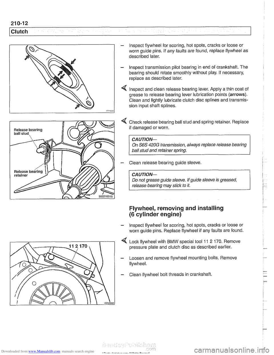
Release bearing
Release
bearin
- lnspect flywheel for scoring, hot spots, cracks or loose or
worn guide pins. If any faults are found, replace flywheel as
described later.
- lnspect transmission pilot bearing in end of crankshaft. The
bearing should rotate smoothly without play. If necessary,
replace as described later.
4 lnspect and clean release bearing lever. Apply a thin coat of
grease to release bearing lever lubrication points (arrows).
Clean and lightly lubricate clutch disc splines and transmis-
sion input
shaft splines.
4 Checlc release bearing ball stud and spring retainer. Replace
if damaged or worn.
CAUTION--
On S6S 420G transmission, always replace release bearing
ball stud and retainer spring.
- Clean release bearing guide sleeve.
CA U TIOG
Do not grease guide sleeve. If guide sleeve is greased,
release bearing may stick to it.
Flywheel, removing and installing
(6 cylinder engine)
- lnspect flywheel for scoring, hot spots, cracks or loose or
worn guide pins. Replace flywheel if any faults are found.
Lock flywheel with BMW special tool
11 2 170. Remove
pressure plate and clutch disc as described earlier.
- Loosen and remove flywheel mounting bolts. Remove
flywheel.
- Clean flywheel bolt threads in crankshaft.
Page 555 of 1002
Downloaded from www.Manualslib.com manuals search engine
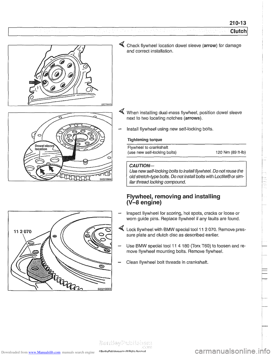
Checlc flywheel location dowel
and correct installation. sleeve (arrow) for
damage
4 When installing dual-mass flywheel, position dowel sleeve
next to two locating notches
(arrows).
- Install flywheel using new self-locking bolts,
Tightening torque Flywheel to cranltshaft
(use new self-locking bolts)
120 Nm (89 ft-lb)
Use new self-lock~ng bolls lo rnslall llylvheel Do not reuse llle
old slrelch-lype bolls Do nor rnsrall bolls wrlh Loct~lo@ or srm-
I ilar thread licking compound. 1
Flywheel, removing and installing
(V-8 engine)
- Inspect flywheel for scoring, hot spots, cracks or loose or
worn guide pins. Replace flywheel if any faults are found.
4 Loclcflywheel with BMW special tool 11 2 070. Remove pres-
sure plate and clutch disc as described earlier.
- Use BMW special tool 11 4 180 (Ton. T60) to loosen and re-
move flywheel mounting bolts. Remove flywheel.
- Clean flywheel bolt threads in crankshaft