light BMW 540i 1998 E39 Owners Manual
[x] Cancel search | Manufacturer: BMW, Model Year: 1998, Model line: 540i, Model: BMW 540i 1998 E39Pages: 1002
Page 648 of 1002
Downloaded from www.Manualslib.com manuals search engine
/~ront Susaension
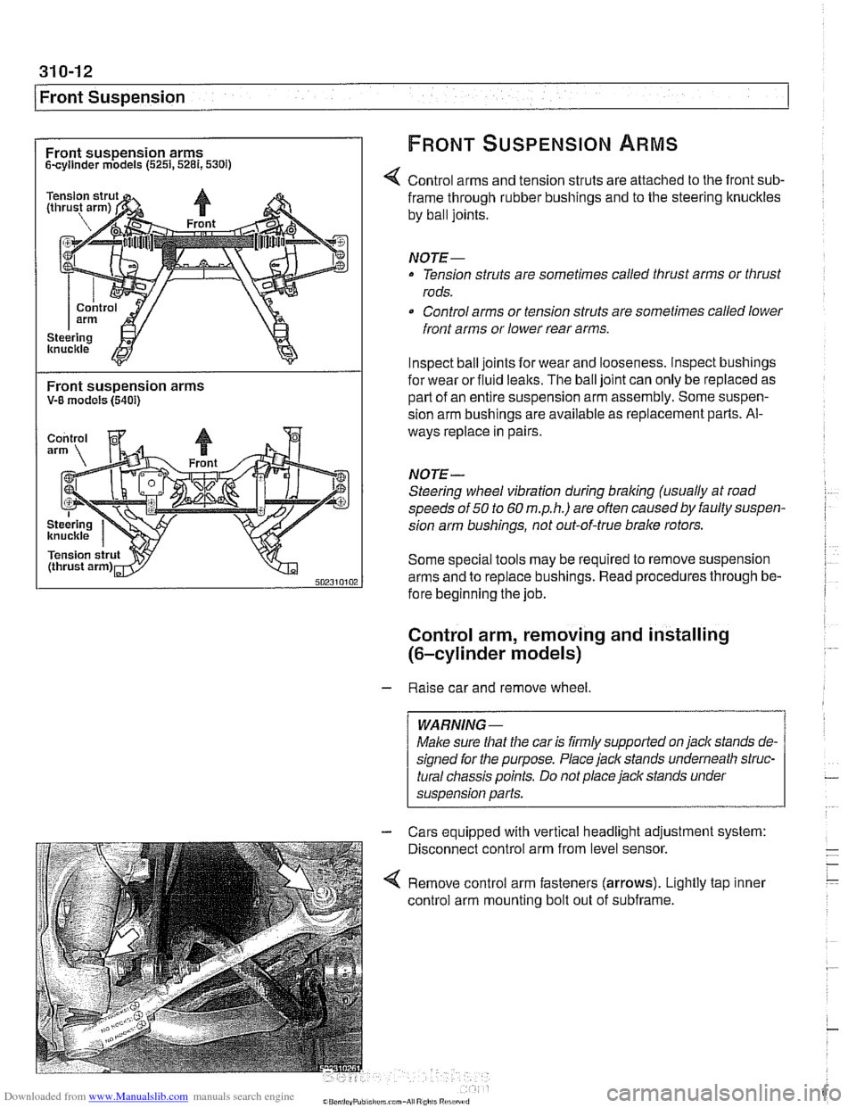
Front suspension arms FRONT SUSPENSION ARMS
Scyllnder models (5251,5281,530i)
Control arms and tension struts are attached to the front sub-
Front suspension arms V-8 models (5401)
frame through rubber bushings and to the steering ltnuckles
by ball joints.
NOTE-
Tension struts are sometimes called thrust arms or thrust
rods.
Control arms or tension struts are sometimes called lower
front arms or lower rear arms.
Inspect ball joints for wear and looseness. lnspect bushings
for wear or fluid
lealts. The ball joint can only be replaced as
part of an entire suspension arm assembly. Some suspen-
sion arm
bushinas are available as re~lacement Darts. Al-
ways replace in pairs
NOTE-
Steering wheel vibration during braking (usually at road
speeds of
50 to 60 m.p.h.) are often causedby faulty suspen-
sion arm bushings, not out-of-true brake rotors.
Some special tools may be required to remove suspension
arms and to replace bushings. Read procedures through be-
fore beginning the job.
Control arm, removing and installing
(6-cylinder models)
- Raise car and remove wheel
Male sure
that the car is firmly supported on jack stands de-
signed for the purpose. Place jack stands underneath struc-
tural chassis points. Do not place jack stands under
suspension
parfs.
Cars equipped with vertical headlight adjustment system:
Disconnect control arm from level sensor.
Remove control arm fasteners (arrows). Lightly tap inner
control arm mounting bolt out of subframe.
Page 649 of 1002
Downloaded from www.Manualslib.com manuals search engine
Front Suspension
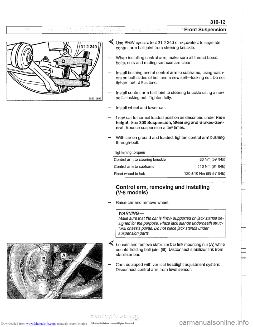
< Use BMW special tool 31 2 240 or equivalent to separate
control arm ball joint from steering ltnuckle.
- When installing control arm, make sure all thread bores.
bolts, nuts and mating surfaces are clean.
- Install bushing end of control arm to subframe, using wash-
ers on both sides of bolt and a new self-locking nut. Do not
tighten nut at this time.
- Install control arm ball joint to steering lknucltle using a new
self-locking nut. Tighten fully.
- Install wheel and lower car.
- Load car to normal loaded position as described under Ride
height. See
300 Suspension, Steering and Brakes-Gen-
eral. Bounce suspension a few times.
- With car on ground and loaded, tighten control arm bushing
through-bolt.
Tightening torques
Control arm to steering ltnuckle
80 Nm (59 ft-lb)
Control arm to subframe 110 Nm (81 It-lb)
Road wheel to hub 120ilO Nm (8957 it-lb)
Control arm, removing and installing
(V-8 models)
- Raise car and remove wheel
WARNING-
Make sure that the car is firmly supported on jack stands de-
signed for the purpose. Place jack stands underneath struc-
tural
cliassis points. Do not place jack stands under
suspension parts.
Loosen and remove stabilizer bar link mounting nut
(A) while
counterholding ball joint
(B). Disconnect stabilizer link from
stabilizer bar.
- Cars equipped with vertical headlight adjustment system:
Disconnect control arm from level sensor.
Page 651 of 1002
Downloaded from www.Manualslib.com manuals search engine
310-1 5
Front ~us~ension/
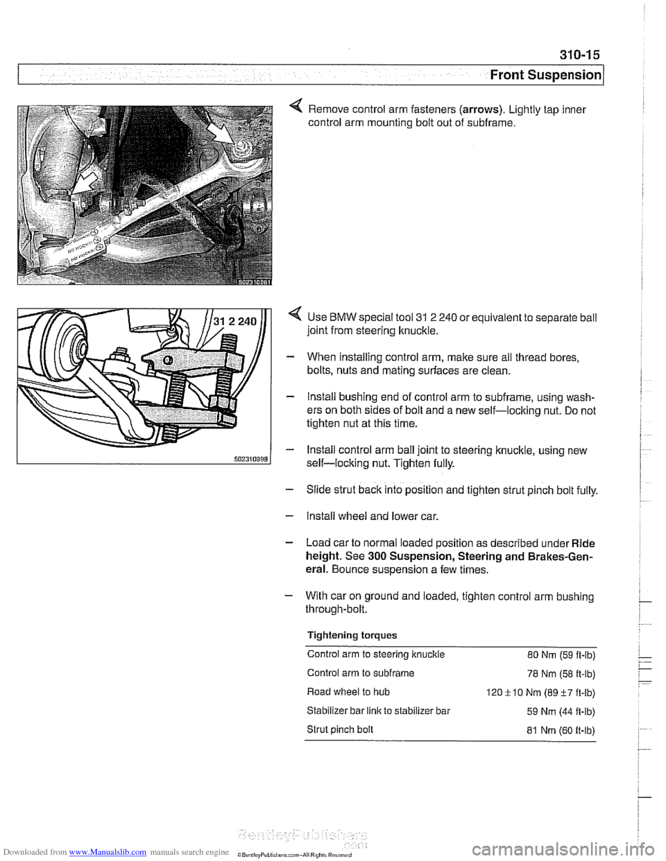
4 Remove control arm fasteners (arrows). Lightly tap inner
control arm mounting bolt out of subframe.
Use
BMW special tool 31 2 240 or equivalent to separate ball
joint from steering knuckle.
When installing control arm, make sure all thread bores,
bolts, nuts and mating surfaces are clean.
lnstall bushing end of control arm to subframe, using wash-
ers on both sides of bolt and a new self-loclting nut. Do not
tighten nut at this time.
lnstall control arm ball joint to steering knuckle, using new
self-locking nut. Tighten fully.
- Slide strut back into position and tighten strut pinch bolt fully.
- Install wheel and lower car.
- Load car to normal loaded position as described under Ride
height. See
300 Suspension, Steering and Brakes-Gen-
eral. Bounce suspension a few times.
- With car on ground and loaded, tighten control arm bushing
through-bolt.
Tightening torques
Control arm to steering knuckle 80 Nm
(59 ft-lb)
Control arm to
subframe 78 Nm (58 ft-lb)
Road wheel to hub
120
f 10 Nm (89 +7 ft-lb)
Stabilizer bar
link to stabilizer bar
59 Nm (44 fl-lb)
Strut pinch bolt
81 Nm (60 it-lb)
Page 728 of 1002
Downloaded from www.Manualslib.com manuals search engine
I Rear Suspension
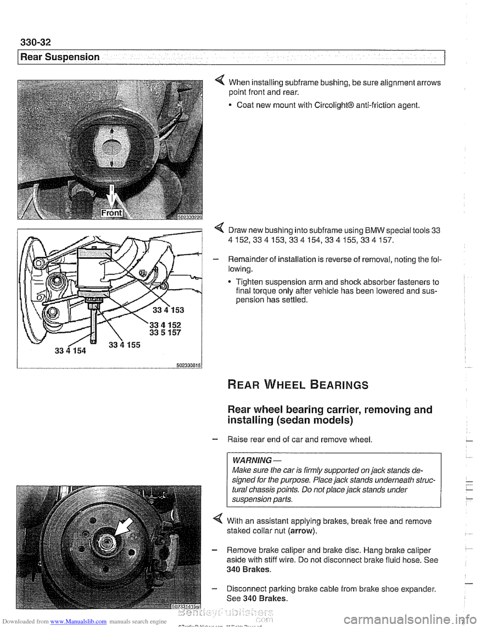
4 When installing subframe bushing, be sure alignment arrows
point front and rear.
Coat new mount with
CircolightB anti-friction agent.
< Draw new bushing into subframe using BMW special tools 33
4152,334153,334154,334155,334157.
- Remainder of installation is reverse of removal, noting the fol-
lowing.
* Tighten suspension arm and shock absorber fasteners to
final torque only after vehicle has been lowered and
sus-
oension has settled.
Rear wheel bearing carrier, removing and
installing (sedan models)
- Raise rear end of car and remove wheel
WARNING-
Make sure the car is firmly supported on jaclc stands de-
signed for the purpose. Place
jaclc stands underneath struc-
tural chassis points. Do not place jaclc stands under
suspension parts.
4 With an assistant applying brakes, break free and remove
staked collar nut (arrow).
- Remove brake caliper and brake disc. Hang brake caliper
aside with stiff wire. Do not disconnect brake fluid hose. See
340 Brakes.
- Disconnect parking brake cable from brake shoe expander.
See 340 Brakes.
Page 730 of 1002
Downloaded from www.Manualslib.com manuals search engine
(Rear Suspension
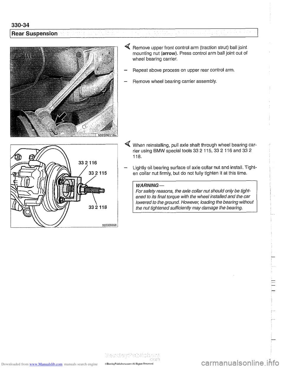
< Remove upper front control arm (traction strut) ball joint
mounting nut
(arrow). Press control arm ball joint out of
wheel bearing carrier.
- Repeat above process on upper rear control arm.
- Remove wheel bearing carrier assembly.
4 When reinstalling, pull axle shaft through wheel bearing car-
rier using
BMW special tools 33 2 115, 33 2 116 and 33 2
118.
- Lightly oil bearing surface of axle collar nut and install. T~ght-
en collar nut firmly, but do not fully tighten it at this time.
WARNING-
For safety reasons, the ale collar nut should only be tight-
ened to its final torque with the wheel installed and the car
lowered to
the ground. However, loading the bearing without
the nut tightened sufficiently may damage tlie bearing.
Page 734 of 1002
Downloaded from www.Manualslib.com manuals search engine
I Rear Suspension
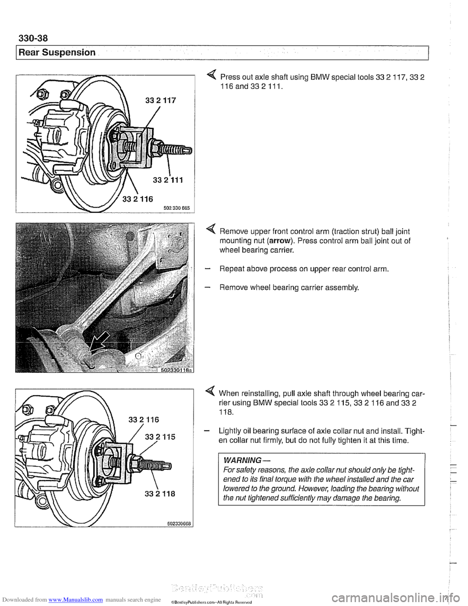
4 Press out axle shaft using BMW special tools 33 2 117. 33 2
116and332111.
4 Remove upper front control arm (traction strut) ball joint
mounting nut (arrow). Press control arm ball joint out of
wheel bearing carrier.
- Repeat above process on upper rear control arm.
- Remove wheel bearing carrier assembly.
4 When reinstalling, pull axle shafl through wheel bearing car-
rier using BMW special tools 33
2 115, 33 2 116 and 33 2
118.
- Lightly oil bearing surface of axle collar nut and install. Tight-
en collar nut firmly, but do not fully tighten it at this time.
WARNING-
For safety reasons, the axle collar nut should only be tight-
ened to its final torque with the wheel installed and the car
lowered to the ground. However, loading the bearing without
the nut tiqhtened
suificiently may darnaqe the bearina.
Page 737 of 1002
Downloaded from www.Manualslib.com manuals search engine
--. ..
Rear Suspension
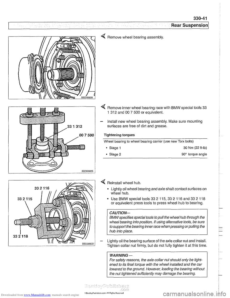
4 Remove wheel bearing assembly.
4 Remove inner wheel bearing race with BMW special tools 33
1 312
and 00 7 500 or equivalent.
- Install new wheel bearing assembly. Malte sure mounting
surfaces are free of dirt and grease.
Tightening torques
Wheel bearing to wheel bearing carrier (use new
Tom bolts)
Stage
1 30 Nm (22 ft-lb)
Stage 2 90" torque angle
4 Reinstall wheel hub.
Lightly oil wheel bearing and axle shaft contact surfaces on
wheel hub.
Use BMW special tools
33 2 115,33 2 116 and 33 2 118
or equivalent press tools to press wheel hub to bearing.
CAUTION-
BMWspecifies speclaltools to pull the wheel hub through the
wheel bearing into position. If using alternative tools, be sure
to support the bearing inner race when pressing orpulling the
hub into place.
- Lightly oil the bearing surface of the axle collar nut and install.
Tighten collar nut firmly, but do not fully tighten it at this time.
WARNING-
For safety reasons, the axle collar nut should only be tight-
ened to its final torque with the wheel installed and the car
lowered to the ground. However, loading the bearing without
the nut tightened sufficiently may damage
the bearing.
Page 756 of 1002
Downloaded from www.Manualslib.com manuals search engine
331-12
Final Drive Final drive cover, removing and installing
- Remove final drive. See Final drive, removing and install-
ing.
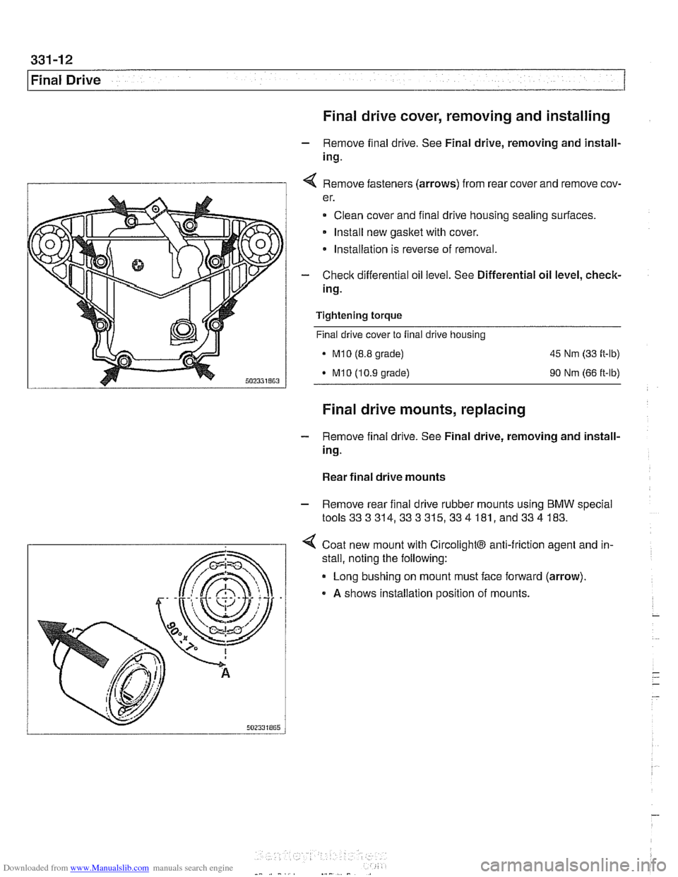
I 1 4 Remove fasteners (arrows) from rear cover and remove cov-
er.
Clean cover and final drive housing sealing surfaces.
Install new
gasket with cover.
* Installation is reverse of removal.
- Check differential oil level. See Differential oil level, check-
ing.
Tightening
torque
Final drive cover to final drive housing
. M10 (8.8 grade) 45 Nm (33 ft-lb)
M10 (10.9 grade) 90 Nm (66 ft-lb)
Final drive mounts, replacing
- Remove final drive. See Final drive, removing and install-
ing.
Rear final drive mounts
- Remove rear final drive rubber mounts using BMW special
tools333314,333315,334 181, and334 183.
4 Coat new mount with CircolightB anti-friction agent and in-
.
stall, noting the following:
Long bushing on mount must face forward (arrow).
A shows installation position of mounts.
Page 757 of 1002
Downloaded from www.Manualslib.com manuals search engine
Final Drive
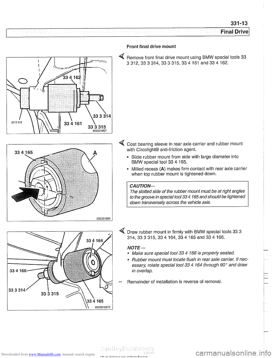
Front final drive mount
4 Remove front final drive mount using BMW special tools 33
3312,333314, 333315,334161
and334162.
I i 4 Coat bearing sleeve in rear axle carrier and rubber mount
with
~ircolight~ anti-friction agent.
Slide rubber mount from side with large diameter into
BMW special tool 33
4 165.
Milled recess
(A) makes firm contact with rear axle carrier
when top rubber mount is tightened down.
The
slolled srde ot r11e rubber mounl must be ar r#ghl angles
lo
rhe groove rn specal roo/ 33 '1 165 and shoulo be lrghrened
I down ~ransversely across the vehicle axis. I
Draw rubber mount in firmly with BMW special tools 33 3
314,333315,334164,334165and334166.
NOTE-
Male sure special tool 33 4 166 is properly seated.
0 Rubber mount must locate flush in rear axle carrier. If nec-
essary, rotate special tool
33 4 164 through 90" and draw
in overlap.
- Remainder of installation is reverse of removal
Page 759 of 1002
Downloaded from www.Manualslib.com manuals search engine
Final ~rivel
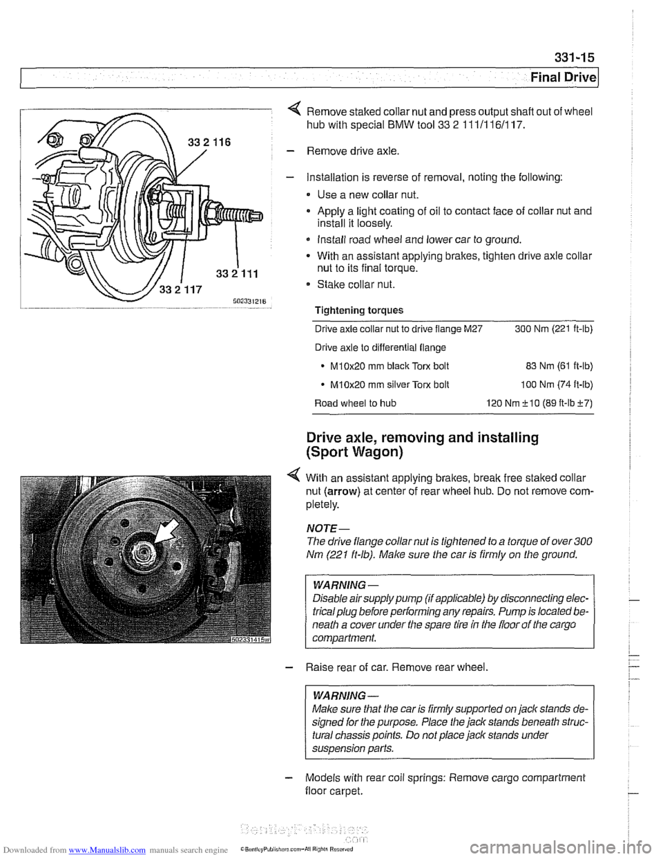
4 Remove staked collar nut and press output shafl out of wheel
hub with special
BMW tool 33 2 111/116/117.
- Remove drive axle.
- Installation is reverse of removal, noting the following:
Use a new collar nut.
a Apply a light coating of oil to contact face of collar nut and
install it loosely.
* Install road wheel and lower car to ground.
- With an assistant applying brakes, tighten drive axle collar
nut to its final torque.
Stake collar nut.
Tightening torques
-
Drive axle collar nut to drive flange M27 300 Nrn (221 ft-lb)
Drive axle to differential flange
* M10x20 rnm black Torx bolt
83 Nrn (61 ft-lb)
M10x20 rnrn silver Torx bolt
100 Nrn (74 ft-lb)
Road wheel to hub 120 Nrn f 10 (89 ft-lbf7)
Drive axle, removing and installing
(Sport Wagon)
4 With an assistant applying brakes, brealc free staked collar
nut (arrow) at center of rear wheel hub. Do not remove com-
pletely.
NOJE-
The drive flange collar nut is tightened to a torque of over 300
Nm (221 ft-lb). Make sure the car is firmly on the ground.
WARNING -
Disable airsupply pump (if applicable) by disconnecting elec-
tricalplug before performing any repairs. Pump is located be-
neath a cover under the spare tire
in the floor of the cargo
compartment.
- Raise rear of car. Remove rear wheel.
WARNING -
Malce sure that the car is firmly supported on jack stands de-
signed for the purpose. Place the jack stands beneath struc-
tural chassis points. Do not place jack stands under
suspension parts.
- Models with rear coil springs: Remove cargo compartment
floor carpet.