light BMW 540i 1998 E39 Workshop Manual
[x] Cancel search | Manufacturer: BMW, Model Year: 1998, Model line: 540i, Model: BMW 540i 1998 E39Pages: 1002
Page 892 of 1002
Downloaded from www.Manualslib.com manuals search engine
51 3-1 4
llnterior Trim
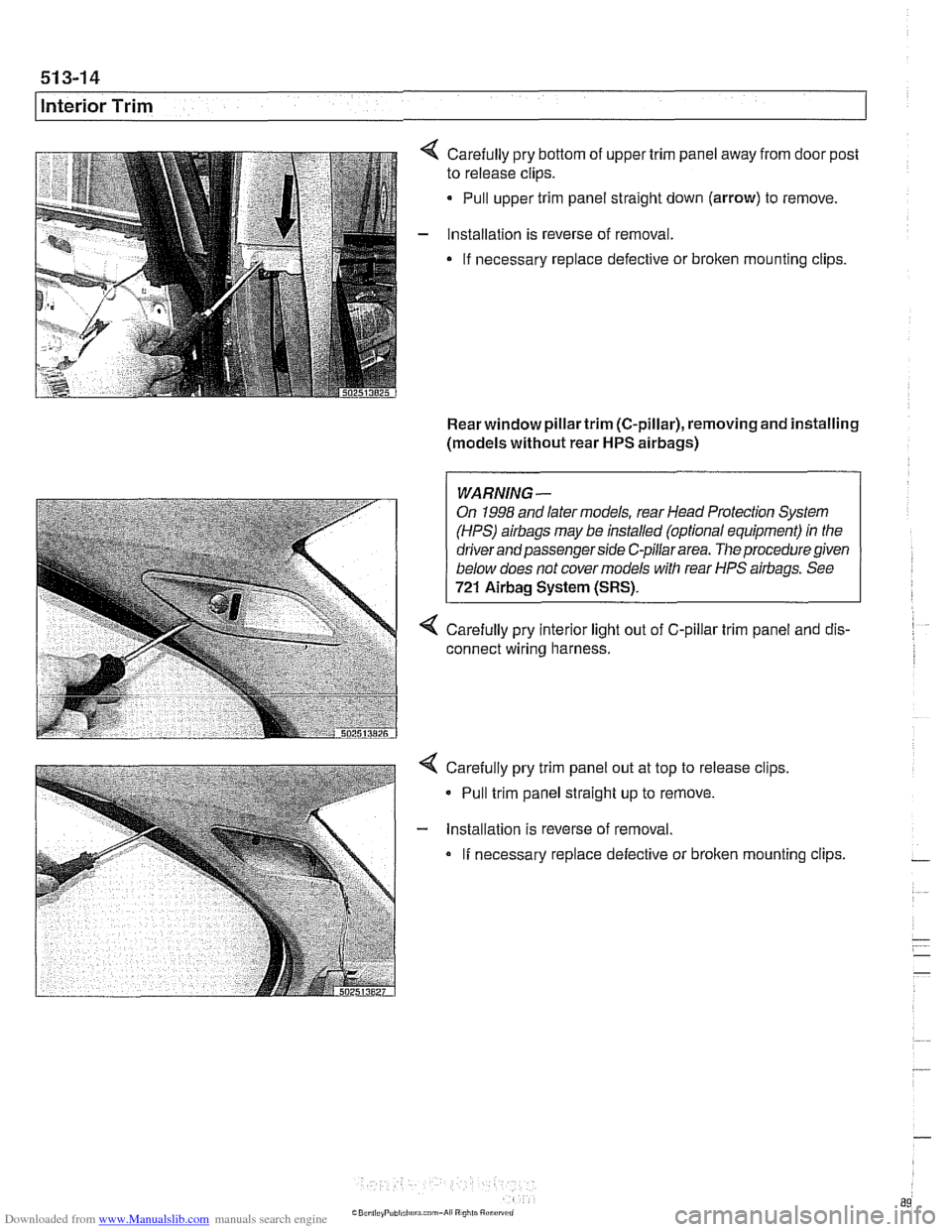
Carefully pry bottom of upper trim panel away from door post
to release clips.
Pull upper trim panel straight down (arrow) to remove.
Installation is reverse of removal.
If necessary replace defective or
broken mounting clips.
Rear window pillartrim (C-pillar), removing and installing
(models without rear
HPS airbags)
1 I
WARNING-
On 1998 and later models, rear Head Protection System
(HPS)
airbags may be installed (optional equipment) in the
driver and passenger side C-pillar area.
The procedure given
below does not cover models with rear HPS airbags. See
721 Airbag System (SRS).
4 Carefully pry interior light out of C-pillar trim panel and dis-
connect wiring harness.
Carefully pry trim panel out at top to release clips,
- Pull trim panel straight up to remove.
- lnstallation is reverse of removal.
If necessary replace defective or broken mounting clips.
Page 901 of 1002
Downloaded from www.Manualslib.com manuals search engine
Central Locking and Anti-Theft
Trunk lock
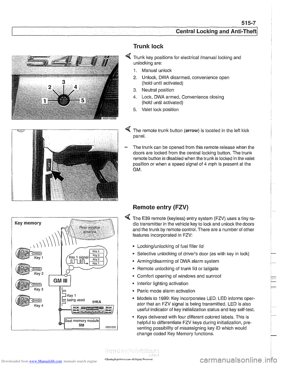
6 Tr~nk ftey pos~rions for eecir'cal mama, locking and
-nlock~ng are:
1. Manual unock .. - - - ........ - ..- .- ................. s.=.=-- 2. Unlock. DWA oisarmed, conven:ence open
(nold
un1:l aclivaledj
3. Ne~tral posit'on
1. -ocn. DWA armeo, Convenience closng
(hold ~nti activated)
5. Valet .oc,t position
. -- .............-... .- . - -.....
Key memory
< The remote trunk button (arrow) is located in the lefl lticlc
panel.
- The trunk can be opened from this remote release when the
doors are locked from the central locking button. The
trunk
remote button is disabled when the trunkis loclted in the valet
position or when a speed signal of
4 mph is present at the
GM.
Remote entry (FZV)
< The €39 remote (keyless) entry system (FZV) uses a tiny ra-
dio transmitter in the vehicle key to
lock and unlock the doors
and the trunk by remote control. There are a number of other
features incorporated in FZV:
Locltinglunloclting of fuel filler lid
Selective unlocking of driver's door (as with key in lock)
Armingldisarming of DWA alarm system
Remote unlocking of
trunk lid or tailgate
Comfort opening of windows and sunroof
* Interior lighting activation
Panic mode alarm activation
* Models to 1999: Key incorporates LED. LED informs oper-
ator that an FZV signal is being transmitted. LED is also
useful indicator of key initialization status and lkey self-test.
Keys delivered with four different colored labels. This is
helpful to differentiate FZV keys during initialization,
pre.
venting possibility of misassigning key ID which would
change coded Key Memory functions.
Page 903 of 1002
Downloaded from www.Manualslib.com manuals search engine
515-9
Central Locking and ~nti-~heftl
FZV keys
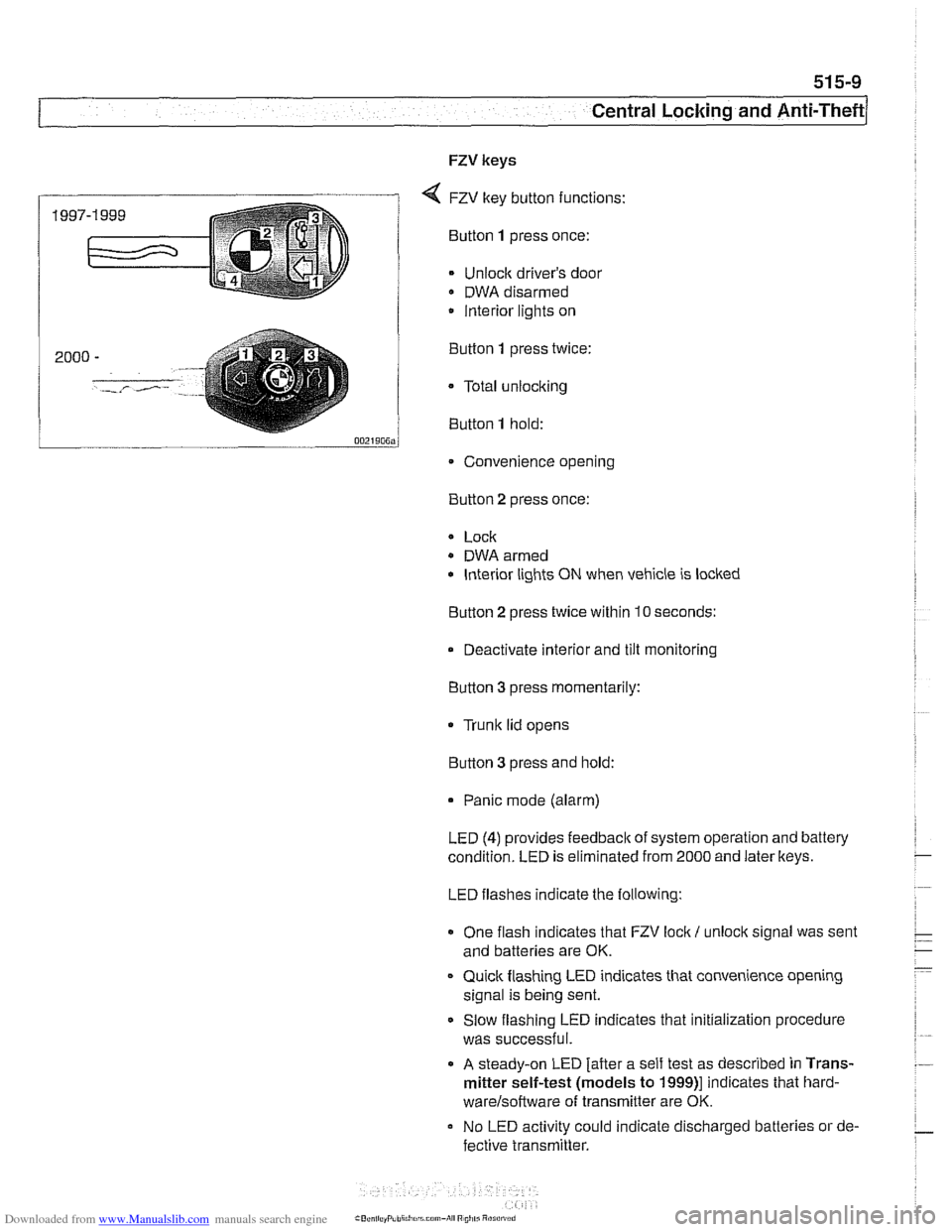
4 FZV key button functions:
Bunon 1 press once:
Unlock driver's door
DWA disarmed
/ lnterior lights on
... - 0021~0~~j
Convenience opening
2000
-
'.-,- /- ..,.
Button 2 press
once:
Button
1 press twice:
a Total
unlocking
Button
1 hold:
* Lock
- DWA armed
lnterior lights ON when vehicle is locked
Button
2 press twice within 10 seconds:
Deactivate interior and tilt monitoring
Button 3 press momentarily:
Trunk lid opens
Button
3 press and hold:
Panic mode (alarm)
LED
(4) provides feedback of system operation and battery
condition. LED is eliminated from 2000 and later
lkeys.
LED flashes indicate the following:
One flash indicates that FZV
lock I unlock signal was sent
and batteries are OK.
Quick flashing LED indicates that convenience opening
signal is being sent.
Slow flashing LED indicates that initialization procedure
was successful.
A steady-on LED [after a self test as described in Trans-
mitter self-test (models to
1999)l indicates that hard-
warelsoftware of transminer are OK.
No LED activity could indicate discharged batteries or de-
fective
transmitter.
Page 906 of 1002
Downloaded from www.Manualslib.com manuals search engine
51 5-12
I Central Locking and Anti-Theft
Key battery
9
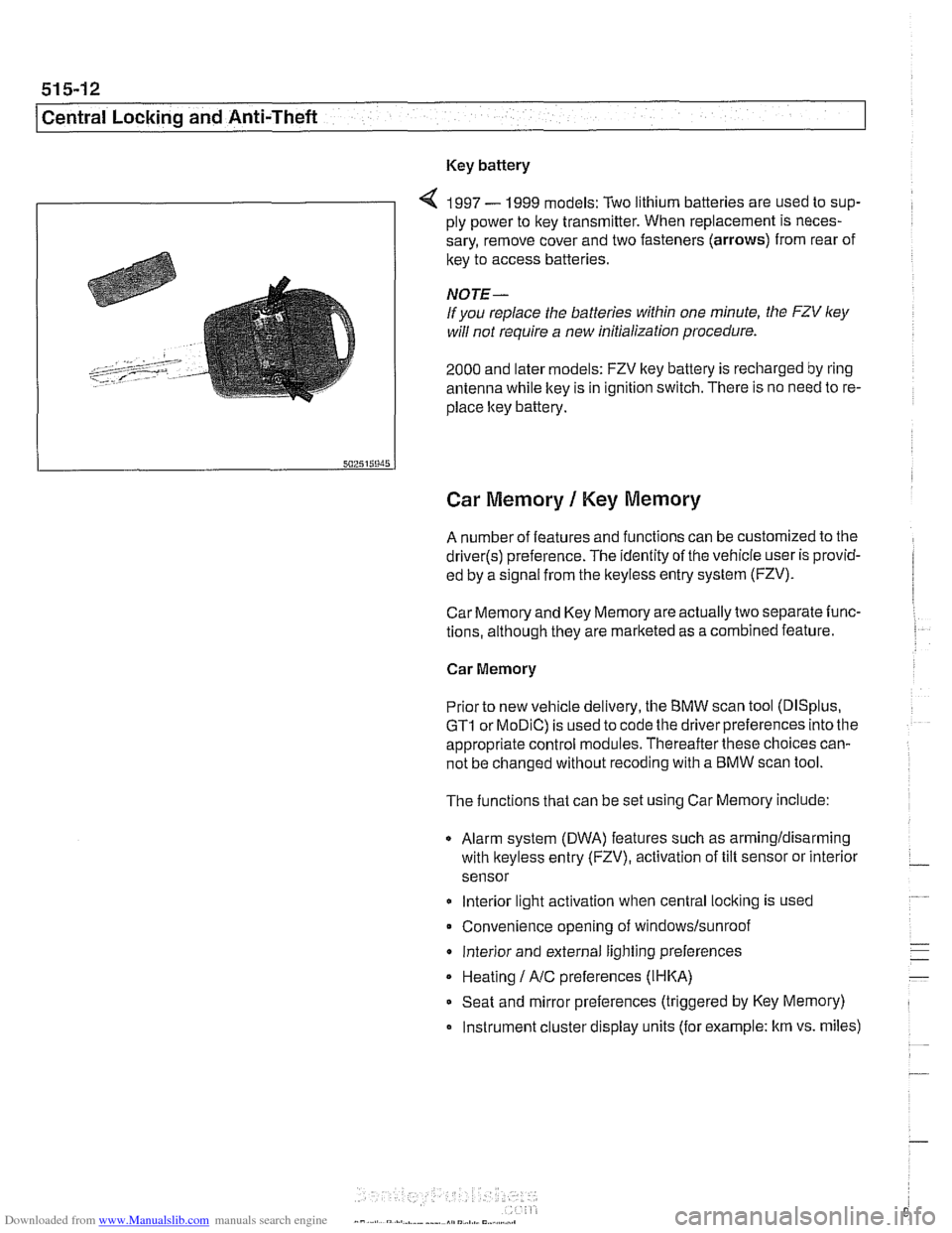
4 1997 - 1999 models: Two lithium batteries are used to sup-
ply power to key transmitter. When replacement is neces-
sary, remove cover and two fasteners (arrows) from rear of
key to access batteries
NOTE-
If you replace the batteries within one minute, the FZV ley
will not require a new initialization procedure.
2000 and later models: FZV key battery is recharged by ring
antenna while ltey is in ignition switch. There is no need to re-
place ltey battery.
Car Memory 1 Key Memory
A number of features and functions can be customized to the
driver(s) preference. The identity of the vehicle user is provid-
ed by a
s~gnal from the keyless entry system (FZV).
Car Memory and Key Memory are actually two separate func-
tions, although they are marketed as a combined feature.
Car Memory
Pr'or ro new
veh c,e de very, the BMW scan roo (DISp us,
GTI or MOD C) is ~sed lo cooc ine driver preierences nro ine
appropriate control modules. Thereafter these choices can-
not be changed without
recoding with a BMW scan tool.
The functions that can be set using Car Memory include:
Alarm system (DWA) features such as armingldisarming
with
lkeyless entry (FZV), activation of tilt sensor or interior
sensor
lnterior light activation when central
locking is used
Convenience opening of
windows/sunroof
lnterior and external lighting preferences
Heating
I A/C preferences (IHKA)
Seat and mirror preferences (triggered by Key Memory)
Instrument cluster display units (for example: km vs. miles)
Page 909 of 1002
Downloaded from www.Manualslib.com manuals search engine
51 5-1 5
Central Locking and Anti-Theft
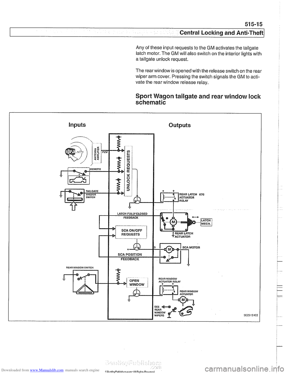
Any of these input requests to the GM activates the tailgate
latch motor. The
GM will also switch on the interior lights with
a tailgate unlock request.
The rearwindow is opened with the release switch on the rear
wiper arm cover. Pressing the switch signals the GM to acti-
vate the rear window release relay.
Sport Wagon tailgate and rear window lock
schematic
Inputs Outputs
"UiRWiNOOW ACTUATOR RELAY
RUiRWINDOW ACTUlimR A L
WIPERS
Page 918 of 1002
Downloaded from www.Manualslib.com manuals search engine
51 5-24
l~entral Locking and Anti-Theft
ANTI-THEFT SYSTEM (DWA)
When the anti-then system (DWA) is armed, the doors, hood,
windows, trunk lid or tailgate are monitored against forcible
entry by switches and sensors. The vehicle is protected
against being jacked up or towed away by a tilt sensor.
The control electronics for DWA are integrated in the General
Module (GM). In addition to the control electronics, the sys-
tem includes the following components.
* DWA horn
DWA LED indicator
- Tilt sensor
- Monitoring switches and sensors
The system can be armed or disarmed from the driver's door
lock,
trunklid lock, tailgate lockorthe remote transmitter (FZV
Itey). When armed, the alarm horn
soundsfor30seconds and
the low beam headlights and turn signals flash for
5 minutes.
The electronic immobilizer (EWS) is also activated when
DWA is activated.
The alarm is switched off immediately if key is inserted in door
loclt or FZV key button is used.
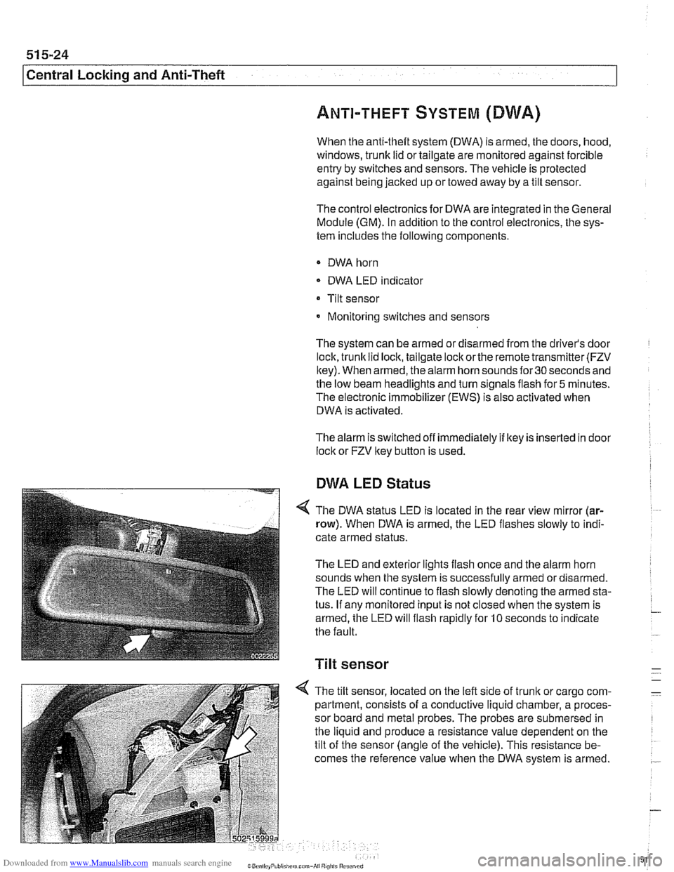
DWA LED Status
The DWA status LED is located in the rear view mirror (ar-
row). When DWA is armed, the LED flashes slowly to indi-
cate armed status.
The LED and exterior lights flash once and the alarm horn
sounds when the system is successfully armed ordisarmed.
The LED will continue to flash slowly denoting the armed sta-
tus. If any monitored input is not closed when the system is
armed, the LED will flash rapidly for
10 seconds to indicate
the fault.
Tilt sensor
-
4 The tilt sensor, located on the left side of trunlt or cargo com- -
partment, consists of a conductive liquid chamber, a proces-
sor board and metal probes. The probes are submersed in
the liquid and produce a resistance value dependent on the
tilt of the sensor (angle of the vehicle). This resistance be-
comes the reference value when the DWA system is armed.
.-
Page 932 of 1002
Downloaded from www.Manualslib.com manuals search engine
-.
Sunroof
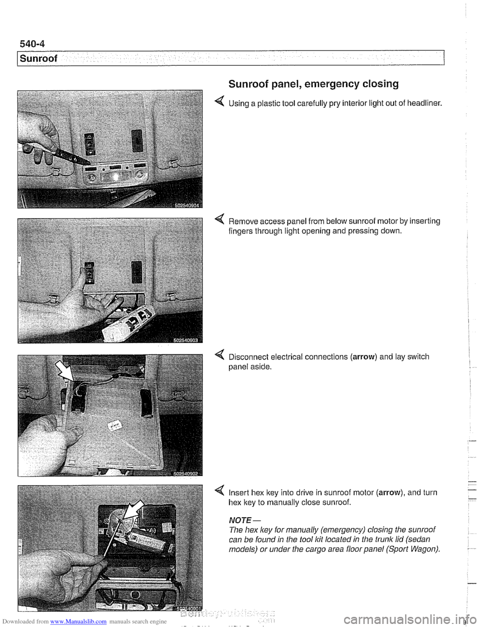
Sunroof panel, emergency closing
4 Using a plastic tool carefully pry interior light out of headliner.
4 Remove access panel from below sunroof motor by inserting
fingers through light opening and pressing down.
4 Disconnect electrical connections (arrow) and lay switch
panel aside.
4 Insert hex ltey into drive in sunroof motor (arrow), and turn
hex ltey to manually close sunroof.
NOTE-
The hex ley for manually (emergency) closing the sunroof
can be found in the tool
Itit located in the trunk lid (sedan
models) or under the cargo area floor panel (Sport Wagon).
Page 938 of 1002
Downloaded from www.Manualslib.com manuals search engine
.-
Sunroof
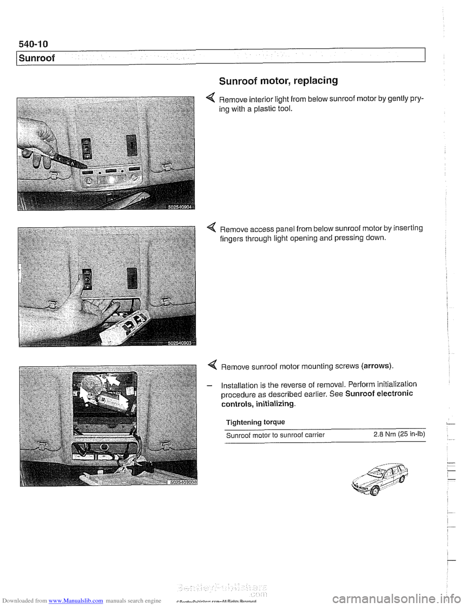
Sunroof motor, replacing
Remove interior light from below sunroof motor by gently pry-
ing with a plastic tool.
4 Remove access panel from below sunroof motor by inserting
fingers through light opening and pressing down.
4 Remove sunroof motor mounting screws (arrows).
- Installation is the reverse of removal. Perform initialization
procedure as described earlier. See Sunroof electronic
controls, initializing.
Tightening
torque
Sunroof motor to sunroof carrier 2.8 Nm (25 in-lb)
Page 949 of 1002
Downloaded from www.Manualslib.com manuals search engine
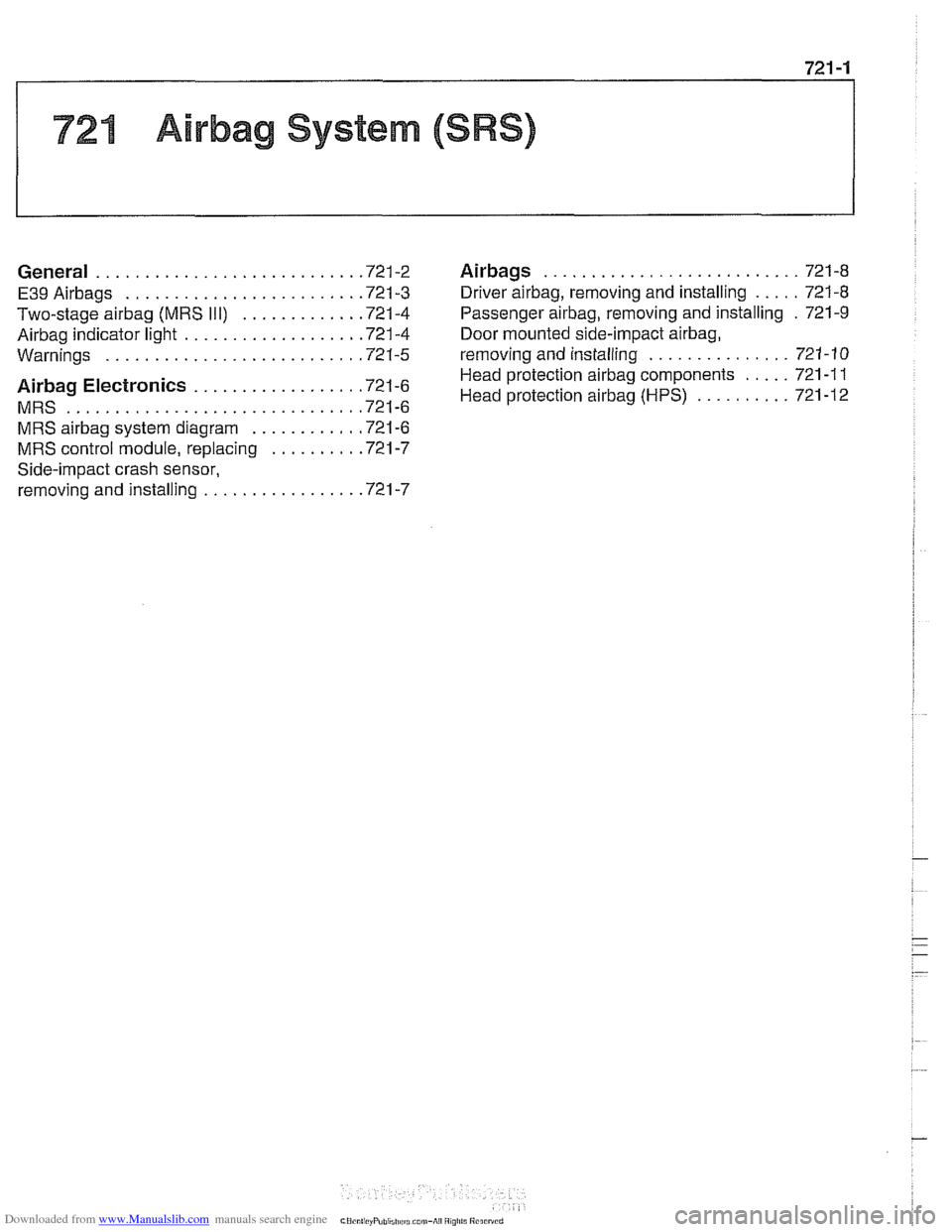
721 Airbag System (SRS)
........................... General ............................ 721-2 Airbags 721-8
..... E39Airbags ......................... 721-3 Driver airbag. removing and installing 721-8
Two-stage airbag (MRS 111) ............ .72 1.4 Passenger airbag. removing and installing . 721-9
Airbag indicator light .................. .72 1.4 Door mounted side-impact airbag.
............... Warninas .......................... .72 1.5 removina and installina 721-10 .
..... Head protection airbag components 721
-1 1 Airbag Electronics ................. '721-6 Head protection airbag (HpS) .......... 721-12 MRS ............................... 721-6
MRS
airbag system diagram ........... .72 1.6
MRS control module. replacing ......... .72 1.7
Side-impact crash sensor.
removing and installing
................ .72 1.7
Page 950 of 1002
Downloaded from www.Manualslib.com manuals search engine
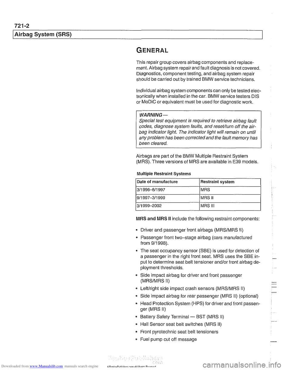
721 -2
l~irba~ System (SRS)
This repair group covers airbag components and replace-
ment.
Airbag system repairand fault diagnosis is not covered.
Diagnostics, component testing, and
airbag system repair
should be carried out by trained BMW service technicians.
Individual
airbag system components can only be tested elec-
tronically when installed in the car. BMW service testers
DIS
or MoDiC or equivalent must be used for diagnostic work.
WARNING-
Special test equipment is required to retrieve airbag fault
codes, diagnose system faults, and
reseffturn off the air-
bag indicator light. The indicator light will remain on until
any problem has been corrected and the fault memory has
been cleared.
Airbags are part of the BMW Multiple Restraint System
(MRS). Three versions of MRS are available in E39 models.
Multiple Restraint Systems
MRS and MRS II include the following restraint components:
311 996-811 997
911
997-311 999
311 999-2002
Driver and passenger front
airbags (MRSIMRS II)
MRS
MRS
II
MRS Ill
Passenger front two-stage airbag (cars manufactured
from
911998).
The seat occupancy sensor (SBE) is used for detection of
a passenger in the right front seat. MRS uses the SBE in-
put to determine seat belt tensioner
and/or front airbag de-
ployment thresholds.
Side impact
airbag for driver and front passenger
(MRSIMRS II)
Leftlright side impact crash sensors (MRSIMRS 11)
Side impact airbag for rear passenger (MRS II) (optional)
Head Protection System (HPS) for driver and front passen-
ger (MRS
II)
Battery Safety Terminal - BST (MRS II)
Hall Sensor seat belt switches (MRS II)
Front pyrotechnic seat belt tensioners
Fuel pump cut off message