light BMW 540i 1998 E39 Manual PDF
[x] Cancel search | Manufacturer: BMW, Model Year: 1998, Model line: 540i, Model: BMW 540i 1998 E39Pages: 1002
Page 469 of 1002
Downloaded from www.Manualslib.com manuals search engine
Fuel Injection I
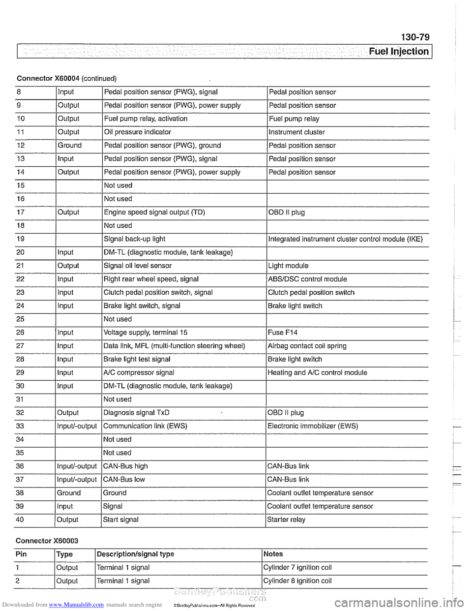
Connector X60004 (continued)
8 10
11
12
13
14
15
16
9
Output 0
Input
17
18
19
20
21
22
23
24
25
26
27
28
29
30
31
32
33
34
35
36
39
llnput lsignal l~oolant outlet temperature sensor
Output
Output
Ground
Input
Output
I I - I
40 /output Istart signal Istarter relay
Pedal position sensor (PWG), signal
Output Input
Output
input
Input
Input
Input
Input
Input
input
Input
Output
Input/-output
Input/-output
37
Connector X60003
Pedal position sensor
Fuel pump relay, activation
Oil pressure indicator Pedal position sensor (PWG), ground
Pedal position sensor (PWG), signal
Pedal position sensor (PWG), power supply
Not used
Not used Fuel
pump relay
Instrument cluster
Pedal position sensor
Pedal position sensor
Pedal position sensor
Engine speed signal output (TD)
Not used
Signal
back-up light
DM-TL (diagnostic module,
tank leakage)
Signal oil level sensor
Right rear wheel speed, signal
Clutch pedal position switch, signal
Brake light switch, signal
Not used
Voltage supply, terminal
15
Data link, MFL (multi-function steering wheel)
Brake light test signal
AJC compressor signal
DM-TL (diagnostic module, tank
leakage)
Not used
Diagnosis signal
TxD
Communication link (EWS)
Not used
Not used
CAN-BUS hiqh
38 1 Ground l~round I Coolant outlet temperature sensor
OED II plug
Integrated instrument cluster control module (IKE)
Light module
ABSIDSC control module
Clutch pedal position switch
Brake light switch
Fuse
F14
Airbag contact coil spring
Brake light switch
Heating and
A/C control module
OBD
II plug
Electronic immobilizer (EWS)
CAN-Bus link
CAN-Bus link
Input/-output CAN-Bus low
Page 474 of 1002
Downloaded from www.Manualslib.com manuals search engine
Fuel Tank and Fuel Pump
Evaporative system troubleshooting
- Start by accessing diagnostic trouble codes (DTCs) using a
BMW or BMW compatible aftermarket scan tool.
For purposes of OBD
II emissions compliance, the DME
system sets a diagnostic trouble code (DTC) when it de-
tects a leak that is equal or larger than minimum
lealc
sensed by system.
Malfunction Indicator Light (MIL) is illuminated upon sec-
ond recurrence of fault. See OBD On-Board Diagnostics.
- When leak testing, observe following conditions to obtain
plausible results:
Fuel tank
'1, to 'I., full.
0 Vehicle parked for at least 2 hours to allow fuel to reach
room temperature.
Ideal fuel temperature is 10"- 20°C
(50"
- 68" F).
Do not refuel immediately before
lealc test.
- If a leak is detected, check the following areas:
* Fuel filter cap (leaking or off).
Fuel tank ventilation lines leaking at fuel
tank or activated
carbon canister.
i
Tank ventilation valve leaking (in engine compartment).
Fuel level
sensorlfuel pump cap leaking.
Evaporative system component replacement is covered later
in
th~s group in Fuel Tank and Fuel Lines.
Page 475 of 1002
Downloaded from www.Manualslib.com manuals search engine
Fuel Tank and Fuel Pump
Warnings and cautions
Observe the following warnings and cautions when servicing
the fuel system.
WARNING-
* The fuel system is designed to retain pressure even when
the ignition is off. When working with the fuelsystem, loos-
en the fuel lines slowly to allow residual
fuel pressure to
dissipate. Avoid spraying fuel. Use shop rags to capture
leaking fuel.
Before beginning any work on the fuel system, place a
fire extinguisher in the vicinity of the work area.
Fuel is highly flammable. When working around fuel, do
not disconnect any wires that could cause electrical
sparks. Do not smoke or worknearheaters or other fire
hazards.
* Always unscrew the fuel tank cap to release pressure
in the
tanlc before working on the tank or lines.
When disconnecting a fuel hose, wrap shop rag around
end of hose to prevent spray of fuel under pressure.
Do not use a work light with an incandescent bulb near
any fuel. Fuel may spray on the hot bulb causing a fire.
0 Make sure the worlc area is properly ventilated.
CAUTION-
- Prior to disconnecting the battery, read the battery discon-
nection cautions given in
001 General Cautions an4
Warnings.
Before
making any electrical tests with the ignition
turned on, disable the ignition system as described in
120 Ignition System. Be sure the battery is discon-
nected when replacing components.
To prevent damage to the ignition system or other DME
components, including the engine control module
(ECM), always connect and disconnect wires and test
equipment with the ignition off.
Cleanliness is essential when
worl~ing with the fuel sys-
tem. Thoroughly clean the fuel line unions before dis-
connecting any of the lines.
Use only clean tools. Keep removed parts clean and
sealed or covered with a clean, lint-free cloth, especial-
ly if completion of the repair is delayed.
Do not move the car while the fuel system is open.
Avoid using high pressure compressed air to blow out
lines and components. High pressure can rupture inter-
nal seals and gaskets.
Always replace seals, O-rings and hose clamps.
Page 511 of 1002
Downloaded from www.Manualslib.com manuals search engine
Radiator and Cooling System
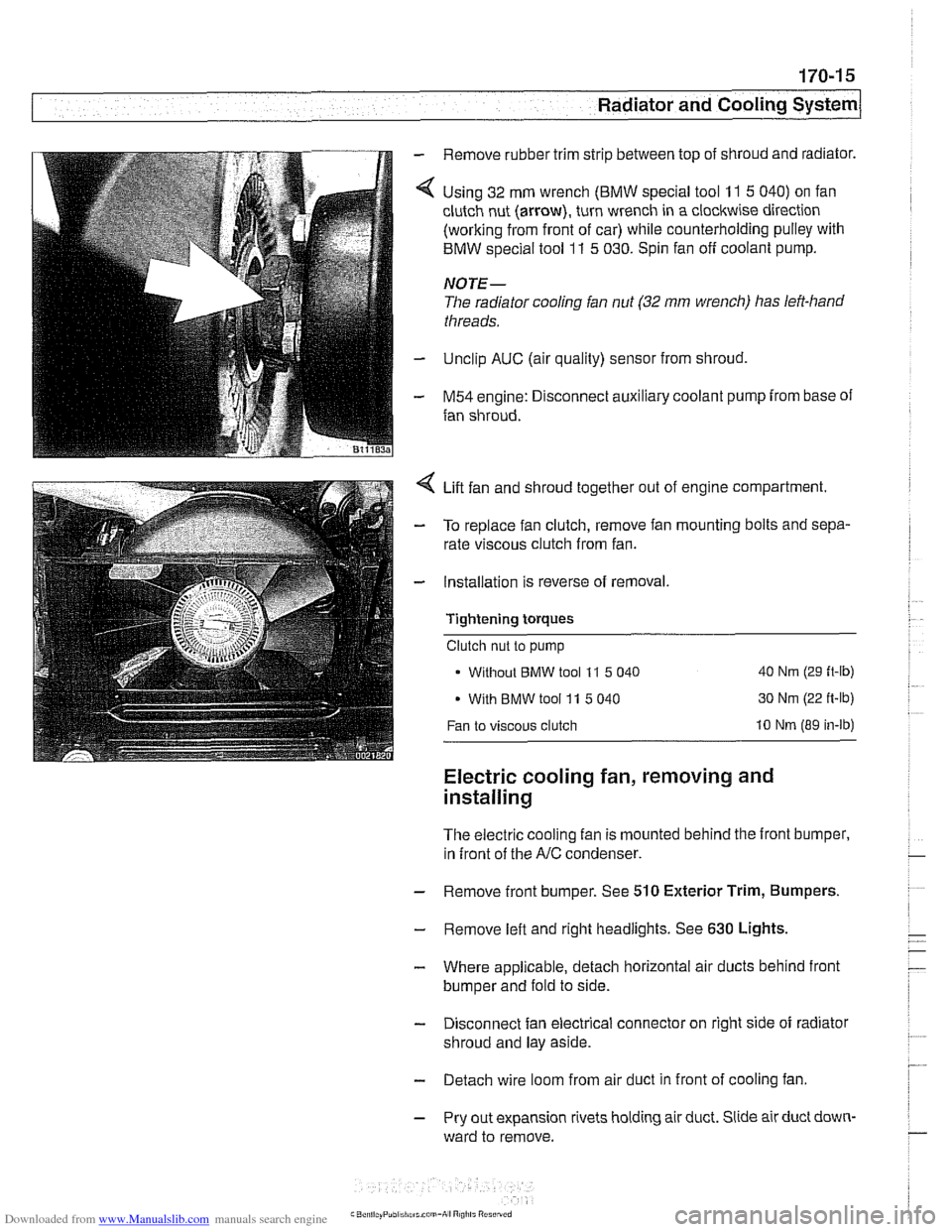
Remove rubber trim strip between top of shroud and radiator.
Using 32 mm wrench
(BMW special tool 11 5 040) on fan
clutch nut (arrow), turn wrench in a clockwise direction
(working from front of car) while counterholding pulley with
BMW special tool
11 5 030. Spin fan off coolant pump.
NOTE-
The radiator cooling fan nut (32 mm wrench) has left-hand
threads.
Unclip AUC (air quality) sensor from shroud,
M54 engine: Disconnect auxiliary coolant pump from base of
fan shroud.
Lift fan and shroud together out of engine compartment.
To replace fan clutch, remove fan mounting bolts and sepa-
rate viscous clutch from fan.
Installation is reverse of removal.
Tightening
torques
Clutch nut to pump
Without
BMW tool 11 5 040 40 Nm (29 ft-lb)
With BMW tool 11 5 040 30 Nm
(22 ft-lb)
Fan to viscous clutch 10 Nm (89 in-lb)
Electric cooling fan, removing and
installing
The electric cooling fan is mounted behind the front bumper,
in front of the
A/C condenser.
- Remove front bumper. See 510 Exterior Trim, Bumpers.
- Remove left and right headlights. See 630 Lights,
- Where applicable, detach horizontal air ducts behind front
bumper and fold to side.
- Disconnect fan electrical connector on right side of radiator
shroud and lay aside.
- Detach wire loom from air duct in front of cooling fan
- Pry out expansion rivets holding air duct. Slide air duct down-
ward to remove.
Page 525 of 1002
Downloaded from www.Manualslib.com manuals search engine
... .
Exhaust System
- With exhaust system fully cold, raise and support car for ac-
cess to exhaust system.
WARNING -
Do not worlc under a lifted car unless it is solidly supported on
jack stands designed for that purpose. Never work under a
car that is supported solely by a
jack.
- Disconnect oxygen sensor connector(s).
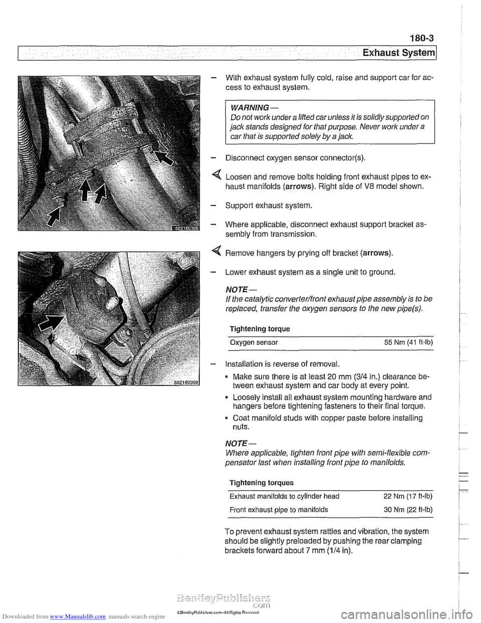
4 Loosen and remove bolts holding front exhaust pipes to ex-
haust manifolds (arrows). Right side of
V8 model shown.
- Support exhaust system
- Where applicable, disconnect exhaust support bracket as-
sembly from transmission.
< Remove hangers by prying off bracket (arrows).
- Lower exhaust system as a single unit to ground.
NOTE-
If the catalytic converterlfront exhaust pipe assembly is to be
replaced, transfer the oxygen sensors to the new
pipe(s).
Tightening torque
Oxygen sensor
55 Nm (41 ft-lb)
- installation is reverse of removal.
* Make sure there is at least 20 mm (314 in.) clearance be-
tween exhaust system and car body at every point.
Loosely install
ail exhaust system mounting hardware and
hangers before tightening fasteners to their final torque.
Coat manifold studs with copper paste before installing
nuts.
NOTE-
Where applicable, tighten front pipe with semi-flexible com-
pensator last when installing front pipe to
manifolds.
Tightening torques
Exhaust manifolds
to cylinder head 22 Nm (1 7 It-lb)
Front exhaust pipe to manifolds 30 Nm (22 ft-lb)
To prevent exhaust system rattles and vibration, the system
should be slightly preloaded by pushing the rear clamping
brackets forward about 7 mm (114 in).
Page 551 of 1002
Downloaded from www.Manualslib.com manuals search engine
- Raise and safely support vehicle
WARNING-
Make sure the car is stable and well supporied at all times.
Use a professional automotive /iff orjack stands designed for
the
ournose. A floor jack is not adeouate suooort.
- If necessary, remove transmission splash shield.
- Disconnect fluid line from slave cylinder on lefl side of trans-
mission. Place pan under hose to catch dripping fluid.
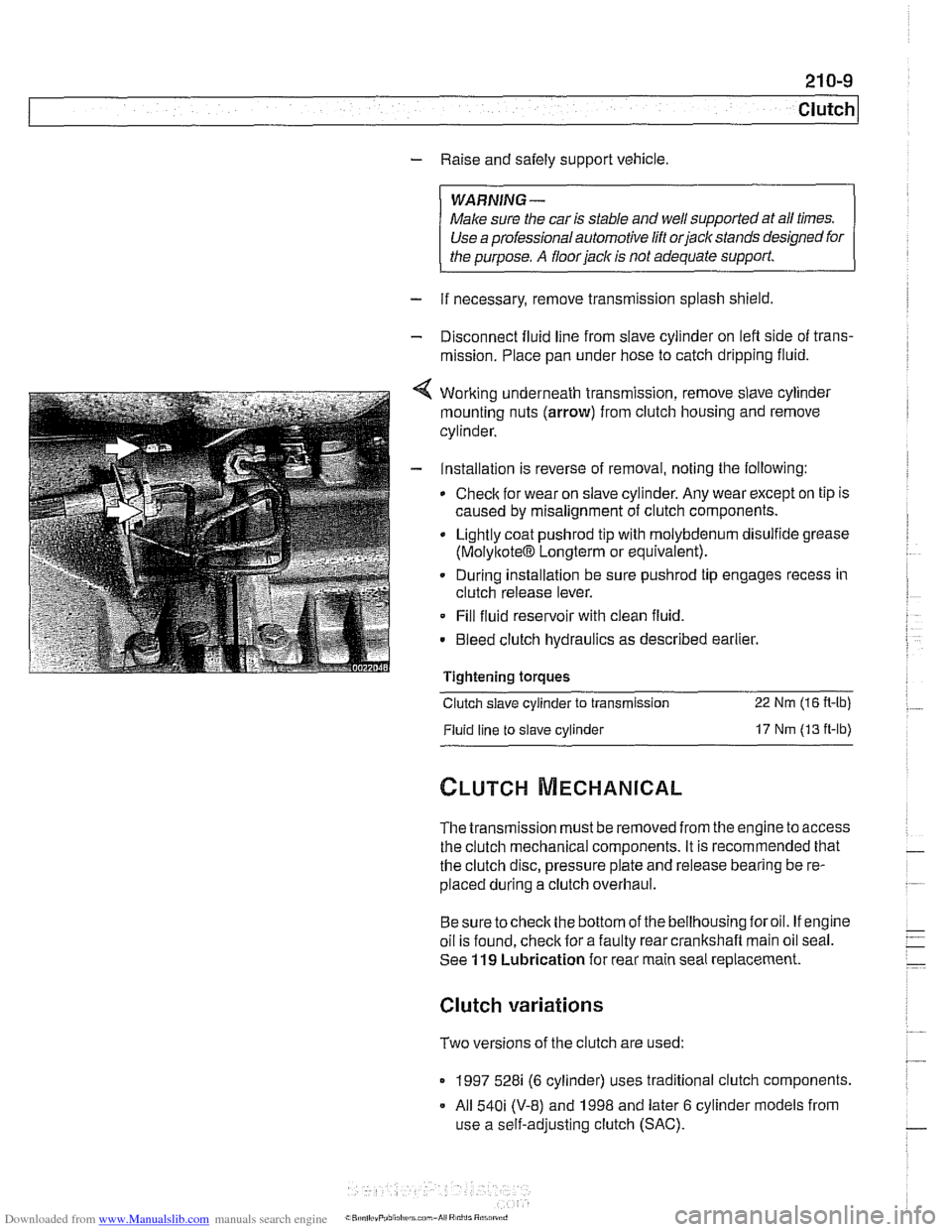
4 Working underneath transmission, remove slave cylinder
mounting nuts (arrow) from clutch housing and remove
cylinder.
- Installation is reverse of removal, noting the following:
Check for wear on slave cylinder. Any wear except on tip is
caused by misalignment of clutch components.
Lightly coat
pushrod tip with molybdenum disulfide grease
(MolyltoteIB Longterm or equivalent).
. During installation be sure pushrod tip engages recess in
clutch release lever.
Fill fluid reservoir with clean fluid.
. Bleed clutch hydraulics as described earlier.
Tightening
toraues - -.
Clutch slave cylinder to transmission 22 Nm (16 R-lb)
Fluid line to slave cylinder 17 Nm (13 ft-lb)
The transmission must be removed from the engine to access
the clutch mechanical components. It is recommended that
the clutch disc, pressure plate and release bearing be re-
placed during a clutch overhaul.
Besure tocheck the bottom of the bellhousing foroil. If engine
oil is found, check for a faulty rear crankshaft main oil seal.
See
119 Lubrication for rear main seal replacement.
Clutch variations
Two versions of the clutch are used:
1997 528i (6 cylinder) uses traditional clutch components.
All
540i (V-8) and 1998 and later 6 cylinder models from
use a self-adjusting clutch (SAC).
Page 554 of 1002
Downloaded from www.Manualslib.com manuals search engine
21 0-1 2
Clutch
Release bearing
Release
bearin
- lnspect flywheel for scoring, hot spots, cracks or loose or
worn guide pins. If any faults are found, replace flywheel as
described later.
- lnspect transmission pilot bearing in end of crankshaft. The
bearing should rotate smoothly without play. If necessary,
replace as described later.
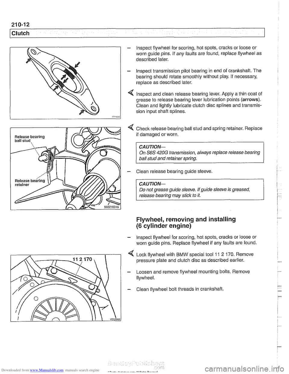
4 lnspect and clean release bearing lever. Apply a thin coat of
grease to release bearing lever lubrication points (arrows).
Clean and lightly lubricate clutch disc splines and transmis-
sion input
shaft splines.
4 Checlc release bearing ball stud and spring retainer. Replace
if damaged or worn.
CAUTION--
On S6S 420G transmission, always replace release bearing
ball stud and retainer spring.
- Clean release bearing guide sleeve.
CA U TIOG
Do not grease guide sleeve. If guide sleeve is greased,
release bearing may stick to it.
Flywheel, removing and installing
(6 cylinder engine)
- lnspect flywheel for scoring, hot spots, cracks or loose or
worn guide pins. Replace flywheel if any faults are found.
Lock flywheel with BMW special tool
11 2 170. Remove
pressure plate and clutch disc as described earlier.
- Loosen and remove flywheel mounting bolts. Remove
flywheel.
- Clean flywheel bolt threads in crankshaft.
Page 556 of 1002
Downloaded from www.Manualslib.com manuals search engine
210-1 4
1 Clutch
Dowel sleeve I
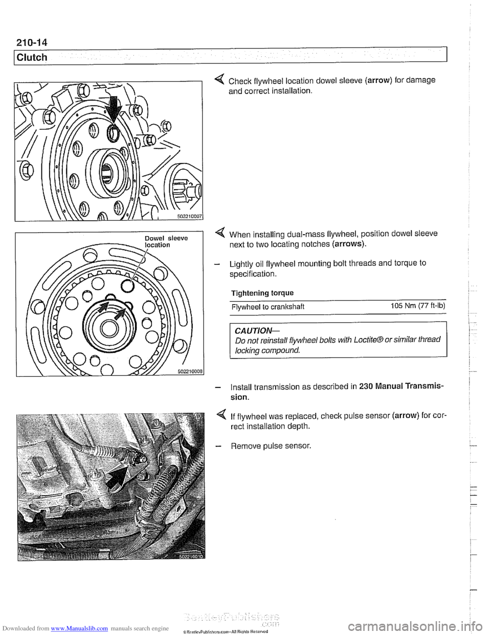
Check flywheel location
and correct installation. dowel sleeve
(arrow)
for . damage
< When installing dual-rnass flywheel, position dowel sleeve
next to two locating notches (arrows).
- Lightly oil flywheel mounting bolt threads and torque to
specification.
Tightening torque
Flywheel to crankshaft 105 Nm (77 ft-lb)
CAUTIOI\C
Do not reinstall flywheel bolls with LoctiteCTJ or similar thread
locl~ing compound.
- Install transm~ssion as descr~bed in 230 Manual Transmis-
sion.
4 If flywheel was replaced, check pulse sensor (arrow) for cor.
rect installation depth.
- Remove pulse sensor.
Page 559 of 1002
Downloaded from www.Manualslib.com manuals search engine
Clutch
- Remove flywheel locking tool
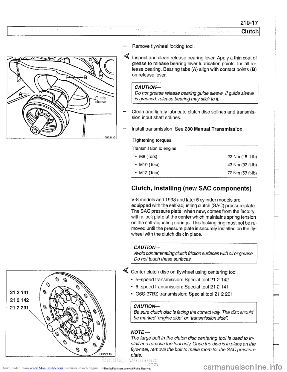
4 Inspect and clean release bearing lever. Apply a thin coat of
grease to release bearing lever lubrication points. Install re-
lease bearing. Bearing tabs
(A) align with contact points (B)
on release lever.
CAUTION-
Do not grease release bearing guide sleeve. If guide sleeve
is greased, release bearing may stick to it.
- Clean and lightly lubricate clutch disc splines and transmis-
sion input shaft splines.
- Install transmission. See 230 Manual Transmission
.
Transmission to engine
MB (Torx) 22 Nm (16 fl-lb)
MlO(Torx) 43 Nm (32 fl-lb)
Clutch, installing (new SAC components)
V-8 models and 1998 and later 6 cylinder models are
equipped with the self-adjusting clutch (SAC) pressure plate.
The SAC pressure plate, when new, comes from the factory
with a lock plate at the center which maintains spring tension
on the self-adjusting springs. This
loclting ring must not be re-
moved until the pressure plate is securely installed on tlie fly-
wheel with the clutch disk in place.
CAUTION-
Avoidcontaminating clutch friction surfaces with oilorgrease.
Do not touch these surfaces.
< Center clutch disc on flywheel using centering tool.
5-speed transmission: Special tool 21 2
142
- 6-speed transmission: Special tool 21 2 141
G6S-3782 transmission: Special tool 21 2 201
CAUTION-
Be sure clutch disc is facing the correct way The disc should
be marked "engine side" or "transmission side':
The large bolt in the clutch disc centering tool is used to
in-
stalland remove the tool only. Once the disc is in place on the
eel, remove the bolt to male room for tlie
SACpressure
Page 560 of 1002
Downloaded from www.Manualslib.com manuals search engine
21 0-1 8
Clutch
- lnstall flywheel lock, special tool 11 2 170 (6 cylinder model)
or
11 2 070 (V-8 model).
- Install SAC pressure plate on dowel pins at flywheel. lnstall
clutch mounting bolts and tighten each one turn at a time until
pressure plate is fully seated. Torque to specification.
Tightening torques Clutch to flywheel
- M8 (8.8 grade)
MB 110.9 orade)
24 Nm (1 8 it-lb)
34 Nm (25
ft-lb)
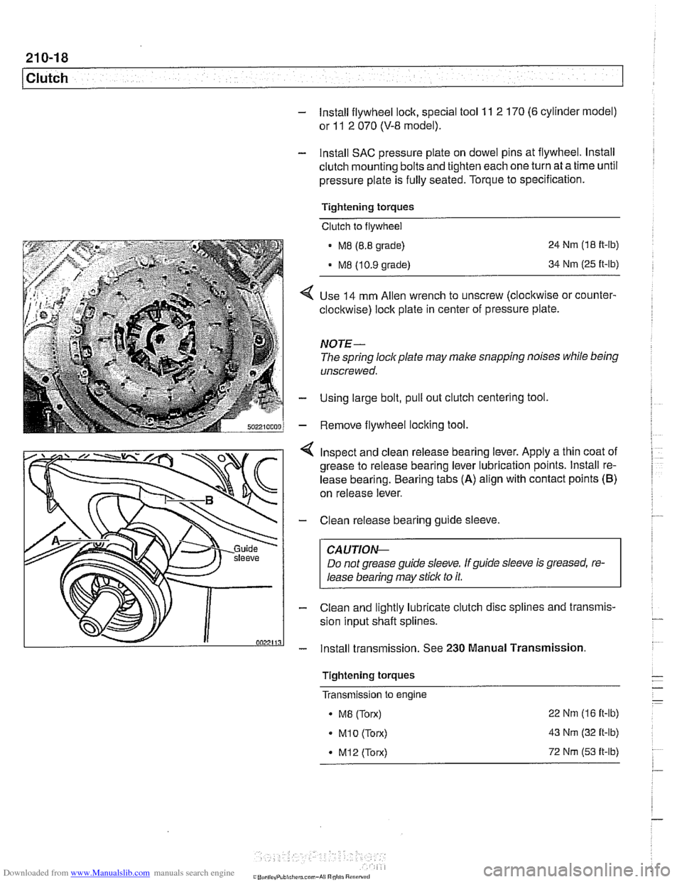
Use 14 mm Allen wrench to unscrew (clocltwise or counter-
clockwise) lock plate in center of pressure plate.
NOTE-
The spring lockplate may make snapping noises while being
unscrewed.
Using large bolt, pull out clutch centering tool
Remove flywheel locking tool
4 Inspect and clean release bearing lever. Apply a thin coat of
grease to release bearing lever lubrication points. lnstall re-
lease bearing. Bearing tabs
(A) align with contact points (B)
on release lever.
- Clean release bearing guide sleeve.
CAUTIOG
Do not grease guide sleeve. Ifguide sleeve is greased, re-
lease bearing may stick to it.
- Clean and lightly lubricate clutch disc splines and transmis-
sion input shaft splines.
- lnstall transmission. See 230 Manual Transmission.
Tightening torques
- - - Transmlsslon to engine -
. MB (Torx) 22
Nm (16 it-lb)
MI0 (Torx) 43 Nm (32 it-lb)
* M12 (Torx) 72 Nm (53 it-lb)
.-