light BMW 540i 1998 E39 Workshop Manual
[x] Cancel search | Manufacturer: BMW, Model Year: 1998, Model line: 540i, Model: BMW 540i 1998 E39Pages: 1002
Page 761 of 1002
Downloaded from www.Manualslib.com manuals search engine
331-17
Final ~rivel
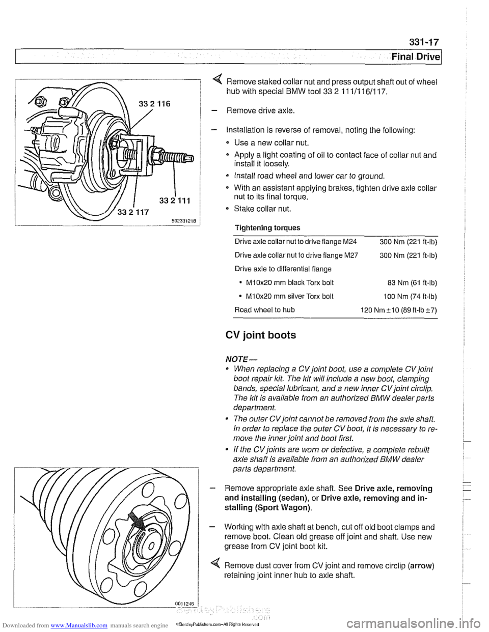
4 Remove staked collar nut and press output shaft out of wheel
hub with special
BMW tool 33 2 11 111 161117.
- Remove drive axle
- Installation is reverse of removal, noting the following:
* Use a new collar nut.
- Apply a light coating of oil to contact face of collar nut and
install it loosely.
Install road wheel and lower car to ground.
* With an assistant applying brakes, tighten drive axle collar
nut to its final torque.
Stake collar nut.
Tightening
torques
Drive axle collar nut to drive flange M24
300 Nrn (221 ft-lb)
Drive axle collar nut to drive flange M27
300 Nrn (221 ft-lb)
Drive axle to differential flange
M10x20 rnrn blaclc Torx bolt 83 Nrn (61 it-lb)
- M10x20 rnrn silver Torx bolt loo Nrn (74 ft-lb)
Road wheel to hub
120 Nrn+lO (89tt-lbi-7)
CV joint boots
NOTE-
When replacing a CVjoint boot, use a complete CVjoint
boot repair kit. The lit will include a new boot, clamping
bands, special lubricant, and a new inner CV joint circlip.
The lit is available from an authorized
BMW dealerparts
department.
The outer CVjoint cannot be removed from the axle
shaft
In order to replace the outer CV boot, it is necessary to re-
move the inner joint and boot first.
If the
CVjoints are worn or defective, a complete rebuilt
axle shaft is available from an authorized
BMW dealer
parts department.
- Remove appropriate axle shaft. See Drive axle, removing
and installing (sedan), or Drive axle, removing and in-
stalling (Sport Wagon).
- Working with axle shaft at bench, cut off old boot clamps and
remove boot. Clean old grease off joint and shaft. Use new
grease from CV joint boot kit.
4 Remove dust cover from CV joint and remove circlip (arrow)
retaining joint inner hub to axle shaft.
Page 768 of 1002
Downloaded from www.Manualslib.com manuals search engine
340-6
1 Brakes
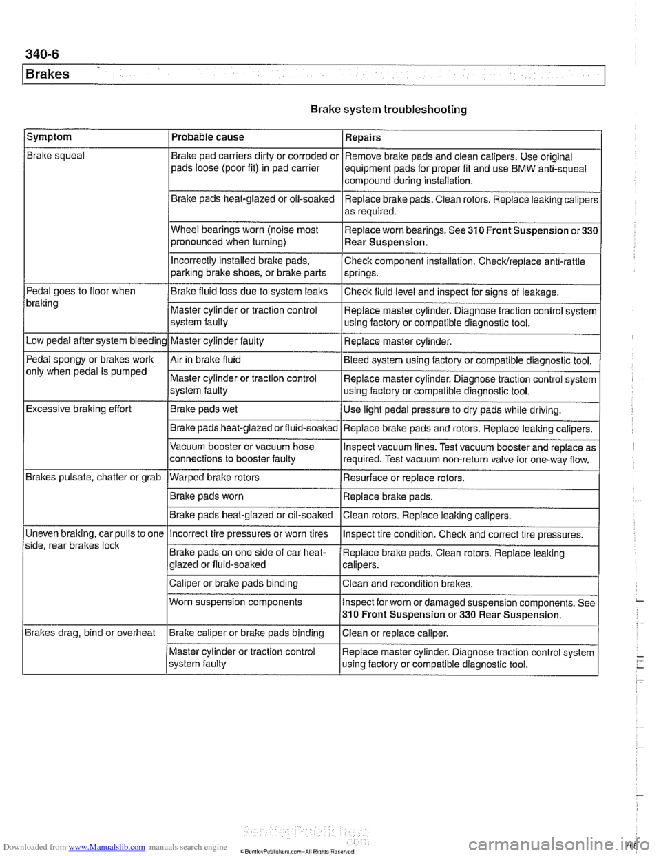
Brake system troubleshooting
/symptom I Probable cause 1 Repairs
Brake squeal
Pedal goes to floor when
bralting
Low pedal after system bleeding
Pedal spongy or brakes work
only when pedal is pumped
Excessive braking effort
Brakes pulsate, chatter or grab
Uneven
bralting, car pulls to one
side, rear braltes
loclt
Brakes drag, bind or overheat Brake
pad carriers dirty or corroded or
pads loose (poor fit) in pad carrier
Braite pads heat-glazed or oil-soaked
Wheel bearings worn (noise most
pronounced when turning)
Incorrectly Installed brake pads,
parking bralte shoes, or bralte parts
Brake fluid loss due to system leaks
Master cylinder or traction control
system faulty
Master cylinder faulty
Air in braite fluid
Master cylinder or traction control
system faulty
Brake pads wet
Brake pads
heat-glazedorfluid-soalted
Vacuum booster or vacuum hose
connections to booster faulty
--- Warped brake rotors
Brake pads worn
Brake pads heat-glazed or oil-soaked Remove
brake pads and clean calipers. Use original
equipment pads for proper fit and use BMW anti-squeal
compound during installation,
Replace brake pads. Ciean rotors. Replace leaking caliper:
as required.
Replace worn bearings. See 310 Front Suspension
or33C
Rear Suspension.
Check component installation. Checldreplace anti-rattle
springs.
Checlt fluid level and inspect for signs of leakage.
Replace master cylinder. Diagnose traction control system
using factory or compatible diagnostic tool.
Replace master cylinder.
Bleed system using factory or compatible diagnostic tool.
Replace master cylinder. Diagnose traction control system
using factory or compatible diagnostic tool.
Use light pedal pressure to dry pads while driving.
Replace
bralte pads and rotors. Replace leaking calipers.
lnspect vacuum lines. Test vacuum booster and replace as
required. Test vacuum non-return valve for one-way flow.
Resurface or replace rotors.
Replace brake pads.
Clean rotors. Replace leaiting calipers.
Incorrect tire pressures or worn tires
Brake pads on one side of car heat-
glazed or fluid-soaked
Caliper or brake pads binding
Worn suspension components
Brake caliper or brake pads binding
Master cylinder or traction control
system faulty lnspect
tire condition. Checlt and correct tire pressures.
Replace brake pads. Clean rotors. Replace leaking
calipers.
Clean and recondition brakes.
Inspect for worn or damaged suspension components. See
310 Front Suspension or 330 Rear Suspension.
Ciean or replace caliper.
Replace master cylinder. Diagnose traction control system
using faclory or compatible diagnostic tool.
Page 776 of 1002
Downloaded from www.Manualslib.com manuals search engine
340-1 4
Brakes
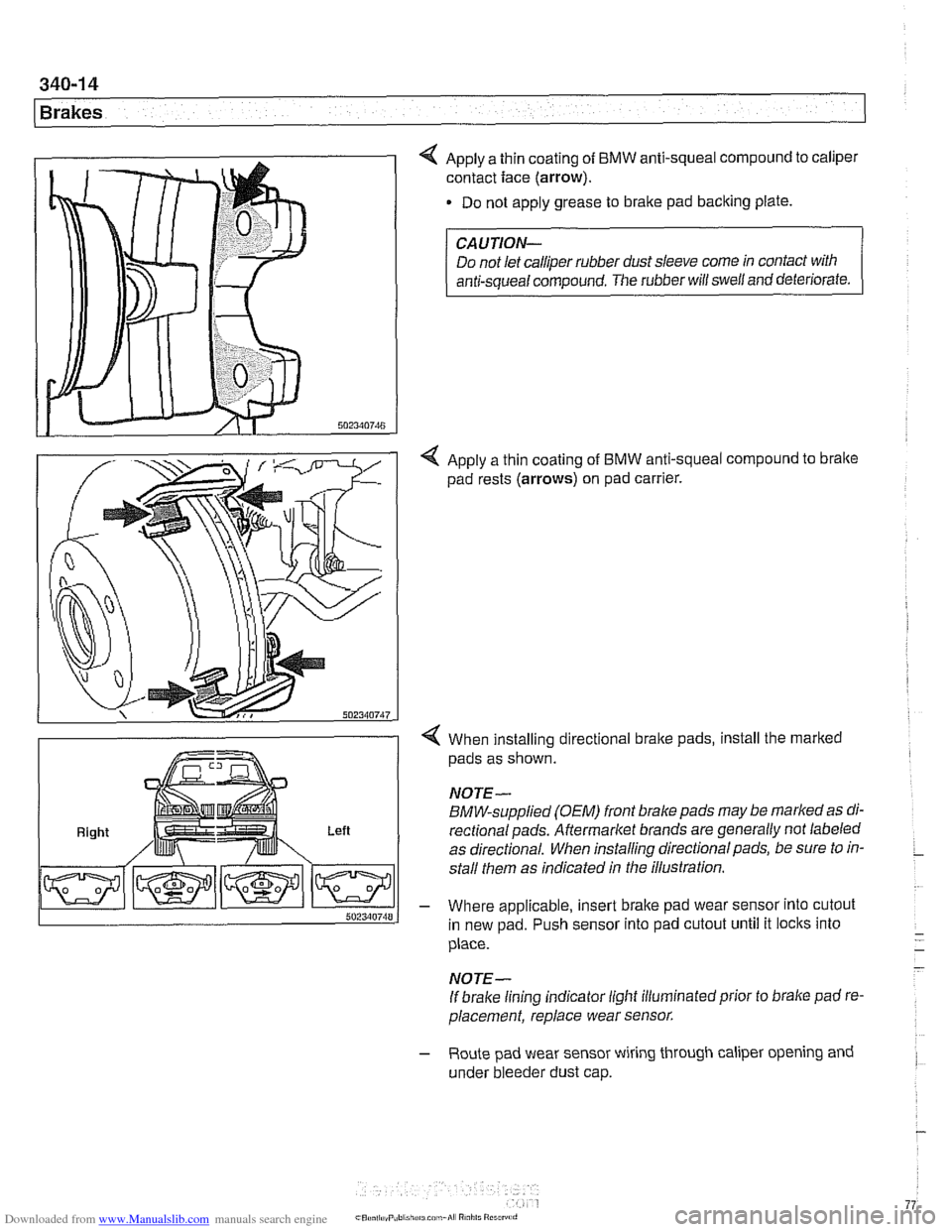
4 Apply a thin coating of BMW anti-squeal compound to caliper
contact face
(arrow).
Do not apply grease to brake pad backing plate.
Right Left
CAUTION-
Do not let calliper rubber dust sleeve come in contact with
anti-squeal compound. The rubber will swell and deteriorate.
4 Apply a thin coating of BMW anti-squeal compound to bralte
pad rests (arrows) on pad carrier.
4 When installing directional brake pads, install the marked
pads as shown.
NOTE-
BMW-supplied (OEM) front brake pads may be marked as di-
rectionalpads. Aftermarket brands are generally not labeled
as directional. When installing directional pads, be sure to in-
stall them as indicated in the illustration.
- Where applicable, insert brake pad wear sensor into cutout
in new pad. Push sensor into pad cutout until it locks into
place.
- -
- NOTE-
If brake lining indicator light illuminatedprior to brake pad re-
placement, replace wear sensor.
- Route pad wear sensor wiring through caliper opening and
under bleeder dust cap.
Page 777 of 1002
Downloaded from www.Manualslib.com manuals search engine
340-1 5
Brakes
- Remainder of installation is reverse of removal.
- Clean brake caliper mounting bolts (7 mm Allen). Replace
ones which are not in perfect condition. Do not grease.
Top up brake fluid to MAX marking.
- Before driving car, pump bralte pedal several times so that
brake pads contact brake rotors.
Check that brake fluid level is correct. Top up if necessary.
Hold ignition key for at least
30 seconds in accessory po-
sition without starting engine. This clears any fault codes in
memory and turns off brake pad warning light.
Tightening torques Brake caliper to pad carrier
(7 mm Allen)
Front caliper
30 Nm (22 It-lb)
- Rear caliper 28 Nm (21 It-lb)
Road wheel to hub
120i 10 Nm (89i7 ft-lb)
Brake rotors, removing and installing
- Raise car and remove wheels
WARNING-
Male sure that the car is firmly supported on jack stands de-
signed for the purpose. Place jack stands beneath structural
chassis points. Do not place jack stands under suspension
parts.
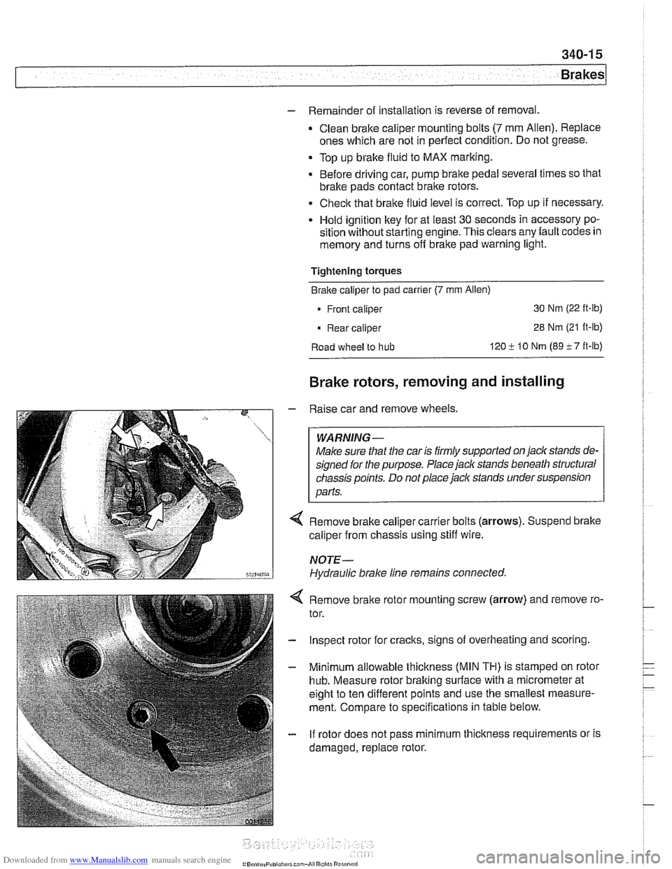
Remove brake caliper carrier bolts (arrows). Suspend brake
caliper from chassis using stiff wire.
NOTE-
Hydraulic brake line remains connected.
4 Remove bralte rotor mounting screw (arrow) and remove ro-
tor.
- Inspect rotor for cracks, signs of overheating and scoring.
- Minimum allowable thickness (MIN TH) is stamped on rotor
hub. Measure rotor braking surface with a micrometer at
eight to ten different points and use the smallest measure-
ment. Compare to specifications in table below.
- If rotor does not pass minimum thickness requirements or is
damaged, replace rotor.
Page 785 of 1002
Downloaded from www.Manualslib.com manuals search engine
340-23
Brakes
- Using flat-bladed screwdriver, reach into brake drum through
lug bolt hole. Turn brake adjuster until wheel no longer turns.
Back adjuster off
12 notches.
Parking brake adjusting (initial)
Back
off adjuster through wheel
lug bolt hole 12 notches
- Working inside car, set parking brake several times to seat
cable. Then pull parking brake
lever up two notches. Tighten
cable adjusting nuts until it is just possible to turn rear wheels
with slight resistance.
- Release lever and make sure rear wheels turn freely
- Turn on ignition. Pull up parlting brake lever 1 notch and
make sure that parking bralte warning light comes on. if not,
adjust parking bralte warning light contact switch.
- Install parking brake lever boot. Install road wheel lug bolts.
Tightening torque Road
wheel to hub 120 i. 10 Nrn (89 i- 7 ft-lb)
Parking brake shoes, removing and
installing
- Raise rear of car and remove road wheels.
WARNING-
Make sure that the car is firmly supported on jack stands de-
signed for
the purpose. Place jack stands beneath structural
chassis points. Do not place
jaclc stands under suspension
parts.
- Without disconnecting brake fluid hose, remove rear bralte
calipers from trailing arms. Remove rear brake rotors as de-
scribed earlier.
CAUTION-
Do not let the brake caliper assembly hang from the brake
hose. Support caliper from chassis with strong wire.
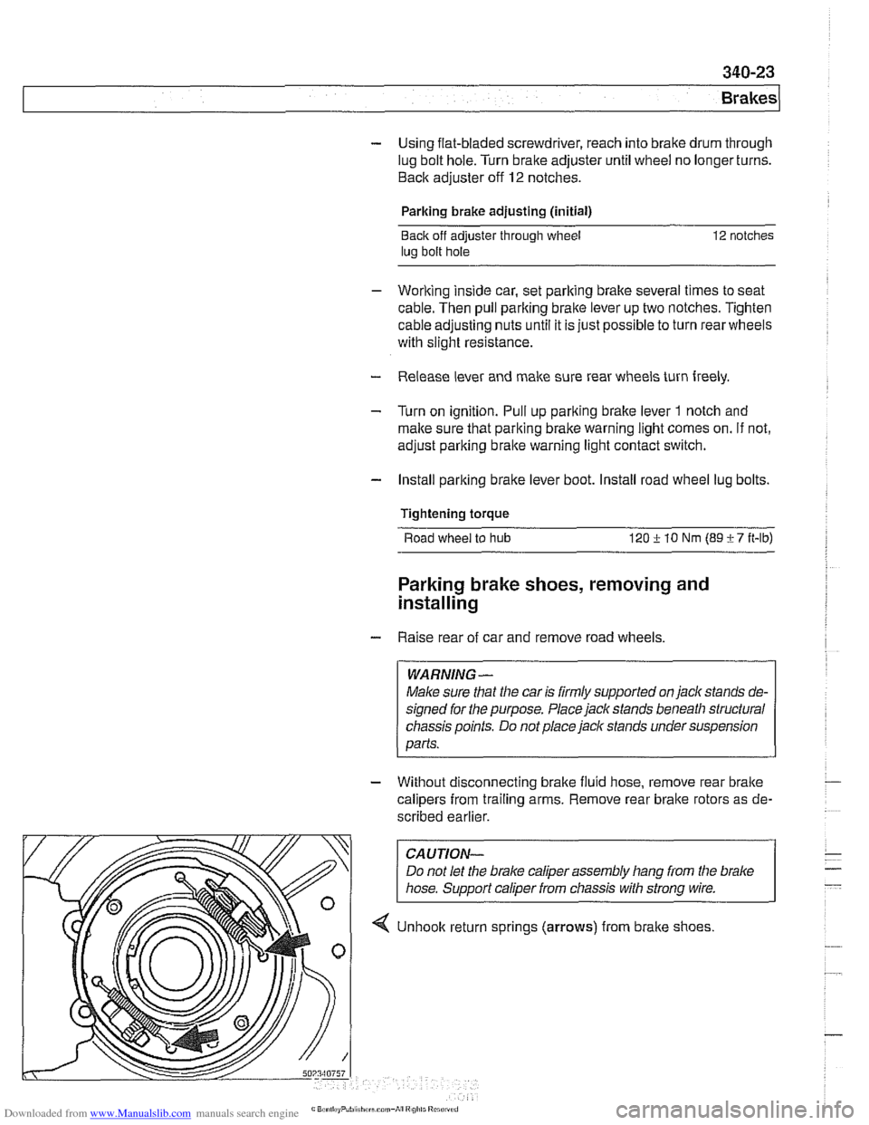
4 Unhook return sprlngs (arrows) from brake shoes
Page 792 of 1002
Downloaded from www.Manualslib.com manuals search engine
1 Brakes
- Remove precharge pump mounting bracket fasteners and re-
move pump.
- Installation is reverse of removal, noting the following:
Be sure to replace rubber pump mounts if damaged
01
worn.
Bleed brakes as described earlier.
Tightening torque Brake line
to precharge pump 18 Nrn (13 ft-lb)
DSC pressure sensor (1 999 - 2002 models)
On 1999 and later DSC systems, the DSC pressure sensor is
screwed into the DSC hydraulic unit (right rear of engine com-
partment).
WARNING-
* €39 cars require special BMW service equipment to prop-
erly bleed the brakes. Removal of the
DSCpressure sensor
is not recommended unless this equipment is available. For
safety reasons, the brake system on cars with ABS must be
bled using the procedures described in this repair group.
Switch off ignition and remove
key to male sure brake
system cannot be activated.
- Disconnect electrical harness connector at switch.
- Use BMW special tool 34 5 160 to remove and install sensor.
Inspect threads and sealing surfaces for damage.
* Work quicltly to avoid excessive brake fluid leakage.
Tightening torque
Pressure sensor
to hydraulic 19 Nrn (14ft-lb)
unit
- Reconnect harness connector
- Bleed front brakes as described earlier.
- Press on brakes and check for leaks at sensor.
- Turn on ignition and firmly depress brake pedal. Check that
DSC warning light does not come on.
Page 797 of 1002
Downloaded from www.Manualslib.com manuals search engine
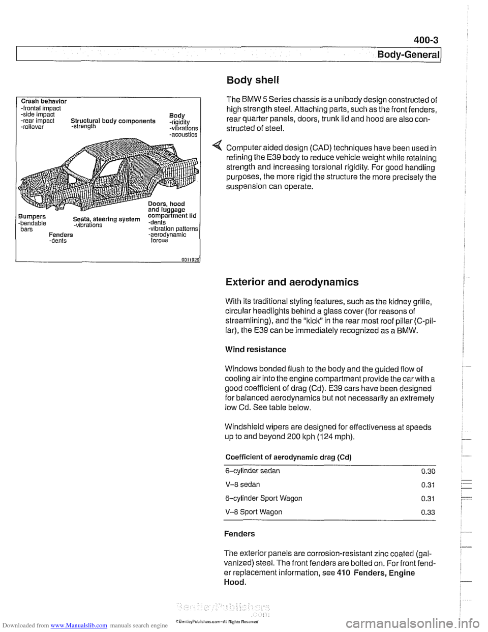
Body shell
Exterior and aerodynamics
Crash behavlor -frontal impact
-side impact
Body
-rear impact Structural body components -rigidity
-rollover -strength -vibrations -acoustics
Bumpers compartment lid -bendable Seets,.steerlng system .dents -vibrations bars -vibration patterns
Fenders -aerodvnamic
With its traditional styling features, such as the ltidney grille.
circular headlights behind a glass cover (for reasons of
streamlining), and the
"kiclt" in the rear most roof pillar (C-pil-
lar), the E39 can be immediately recognized as a BMW.
The BMW 5 Series chassis is a unibody design constructed of
high strength steel. Attaching parts, such as the front fenders,
rear quarter panels, doors,
trunk lid and hood are also con-
structed of
steel.
Computer aided design (CAD) techniques have been used in
refining the
E39 body to reduce vehicle weight while retaining
strength and increasing torsional rigidity. For good handling
purposes, the more rigid the structure the more precisely the
suspension can operate.
Wind resistance
Windows bonded flush to the body and the guided flow of
cooling air into the engine compartment provide the
carwith a
good coefficient of drag (Cd).
E39 cars have been designed
for balanced aerodynamics but not necessarily an extremely
low Cd. See table below.
Windshield wipers are designed for effectiveness at speeds
up to and beyond 200
ltph (124 mph).
Coefficient of aerodynamic drag (Cd)
6-cylinder sedan 0.30
V-8 sedan 0.31
6-cylinder Sport Wagon 0.31
V-8 Sport Wagon 0.33
Fenders
The exterior panels are corrosion-resistant zinc coated (gal-
vanized) steel. The front fenders are bolted on. For front fend-
er replacement information, see
410 Fenders, Engine
Hood.
Page 802 of 1002
Downloaded from www.Manualslib.com manuals search engine
400-8
Body-General
Airbags
Front airbags, s~de a~rbags, pyrotechnic seat belt tensioners
and the Battery Safety Terminal (BST) are integrated into the
Supplemental Restraint System (SRS) and its variants.
NOTE-
The BMW SRS system is called Multiple Restra~nt System
(MRS). Over the years,
E39 cars were equipped with MRS,
MRS
11, MRS 111. Each version offers varied features and im-
provements over the previous system.
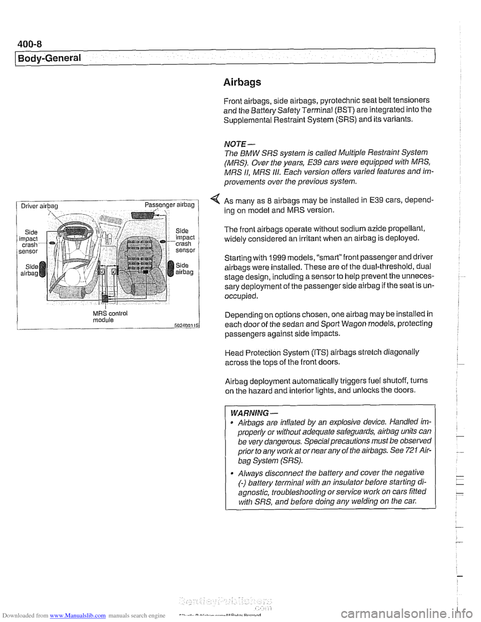
< As many as 8 airbags may be installed in E39 cars, depend-
ing on model and MRS version.
The front
airbags operate without sodium azide propellant,
widely considered an irritant when an
airbag is deployed.
Starting with
1999 models. "smart"front passenger and driver
airbags were installed. These are of the dual-threshold, dual
stage design, including a
sensorto help prevent the unneces-
sary deployment of the passenger side
airbag if the seat is un-
occupied.
MRS control Depend~ng on options chosen, one airbag may be installed in module each door of the sedan and Sport Wagon models, protecting
passengers against
s~de impacts.
Head Protection System (ITS)
airbags strelch diagonally
across the tops of the front doors.
Airbag deployment automatically triggers fuel shutoff, turns
on the hazard and interior lights, and unlocks the doors.
- -
WARNING -
Airbags are inflated by an explosive device. Handled im-
properly or without adequate safeguards,
airbag units can
be very dangerous. Special precautions must be observed
prior to any worlc at or near any of the airbags. See
721 Air-
bag System (SRS).
Always disconnect the battery and cover the negative
(-) battery terminal with an insulator before starting di-
agnostic, troubleshooting or service work on cars fitted
with SRS, and before doing any welding on the
car.
Page 803 of 1002
Downloaded from www.Manualslib.com manuals search engine
400-9
Body-General
Battery safety terminal
(BST)
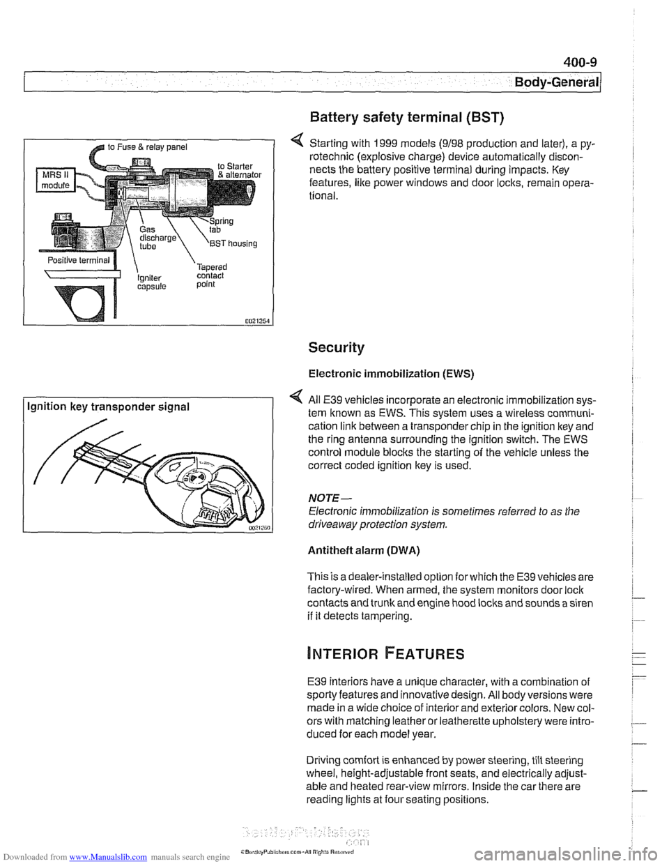
4 Starting with 1999 models (9198 production and later), a py-
rotechnic (explosive charge) device automatically discon-
nects the battery positive terminal during impacts. Key
features,
like power windows and door locks, remain opera-
tional.
Security
Electronic immobilization (EWS)
Ignition key transponder signal All
E39 vehicles incorporate an electronic immobilization sys-
tem known as EWS. This svstem uses a wireless comrnuni-
cation link between a transponder chip in the ignition key and
the ring antenna surrounding the ignition switch. The EWS
control module blocks the starting of the vehicle unless the
correct coded ignition key is used.
NOTE-
Electronic immobilization is sometimes referred to as the
driveaway protection system.
Antitheft alarm (DWA)
This is adealer-installed option for which the E39 vehicles are
factory-wired. When armed, the system monitors door
loci(
contacts and trunk and engine hood locks and sounds a siren
if it detects tampering.
E39 interiors have a unique character, with a combination
of
sporty features and innovativedesign. All body versions were
made in a wide choice of interior and exterior colors. New col-
ors with matching leather or leatherette upholstery were intro-
duced for each model year.
Driving
comfort is enhanced by power steering, tilt steering
wheel, height-adjustable front seats, and electrically adjust-
able and heated rear-view mirrors. Inside the car there are
reading lights at four seating positions.
Page 809 of 1002
Downloaded from www.Manualslib.com manuals search engine
41 0-3
Fenders, Engine ~oodl
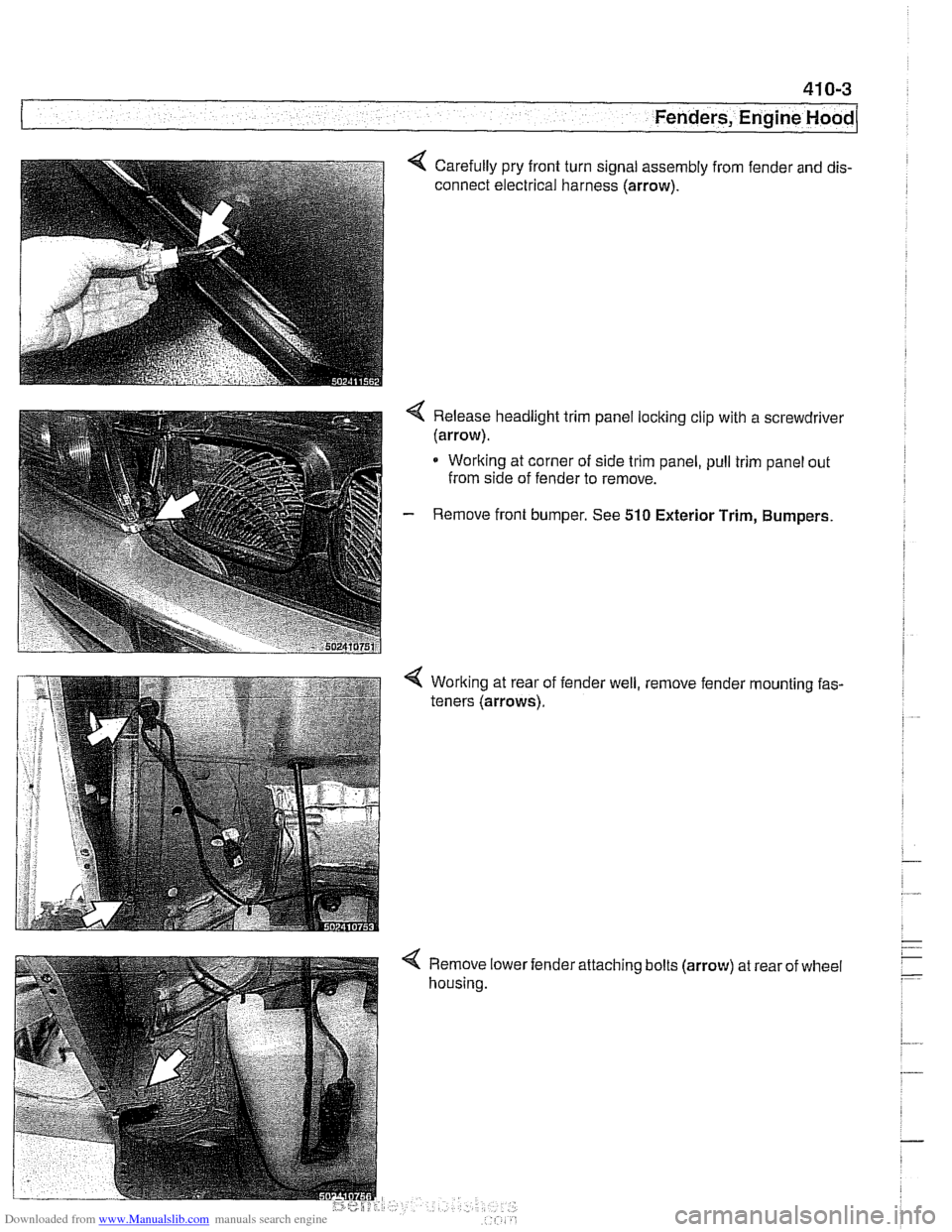
Carefully pry front turn signal assembly from fender and dis-
connect electrical harness (arrow).
< Release headlight trim panel locking clip with a screwdrivel
(arrow).
* Working at corner of side trim panel, pull trim panel out
from side of fender to remove.
- Remove front bumper. See 510 Exterior Trim, Bumpers.
Working at rear of
teners (arrows). fender
well, , remove
fender
'mounting fas-
< Remove lower
housing. 'attaching
bolts
(arrow) at rear of wheel