turn BMW 540i 1999 E39 Workshop Manual
[x] Cancel search | Manufacturer: BMW, Model Year: 1999, Model line: 540i, Model: BMW 540i 1999 E39Pages: 1002
Page 809 of 1002
Downloaded from www.Manualslib.com manuals search engine
41 0-3
Fenders, Engine ~oodl
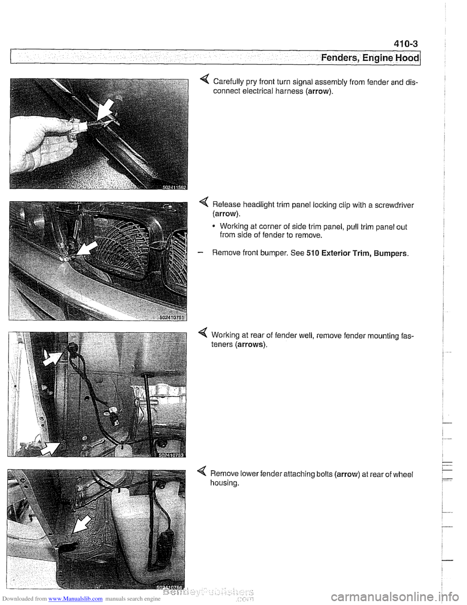
Carefully pry front turn signal assembly from fender and dis-
connect electrical harness (arrow).
< Release headlight trim panel locking clip with a screwdrivel
(arrow).
* Working at corner of side trim panel, pull trim panel out
from side of fender to remove.
- Remove front bumper. See 510 Exterior Trim, Bumpers.
Working at rear of
teners (arrows). fender
well, , remove
fender
'mounting fas-
< Remove lower
housing. 'attaching
bolts
(arrow) at rear of wheel
Page 817 of 1002
Downloaded from www.Manualslib.com manuals search engine
Fenders, Ensine HOO~I
Hood release cable and spring pins,
adjusting
Before adjusting hood pins, be sure the hood is aligned even-
ly to fenders and front panel.
- Malte sure bowden cable, which connects both hood loclts
together, is seated in lock guide on both left and right loclts.
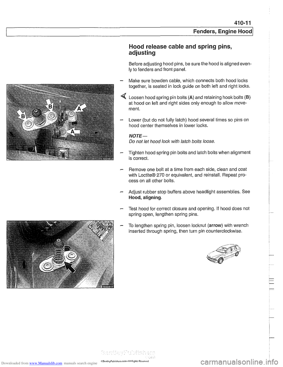
4 Loosen hood spring pin bolts (A) and retaining hoolt bolts (B)
at hood on left and right sides only enough to allow move-
ment.
- Lower (but do not fully latch) hood several times so pins on
hood center themselves in lower loclts.
NOTE-
Do not let hood lock with latch bolts loose
- Tighten hood spring pin bolts and latch bolts when alignment
is correct.
- Remove one bolt at a time from each side, clean and coat
with
LoctiteB 270 or equivalent, and reinstall. Repeat pro-
cess on all other bolts.
- Adjust rubber stop buffers above headlight assemblies. See
Hood, aligning.
- Test hood for correct closure and opening. If hood does not
spring open, lengthen spring pins.
- To lengthen spring pin, loosen locltnut (arrow) with wrench
inserted through spring, then turn pin counterclocltwise.
Page 832 of 1002
Downloaded from www.Manualslib.com manuals search engine
/~runk Lid, Tailgate
Trunk lid, adjusting
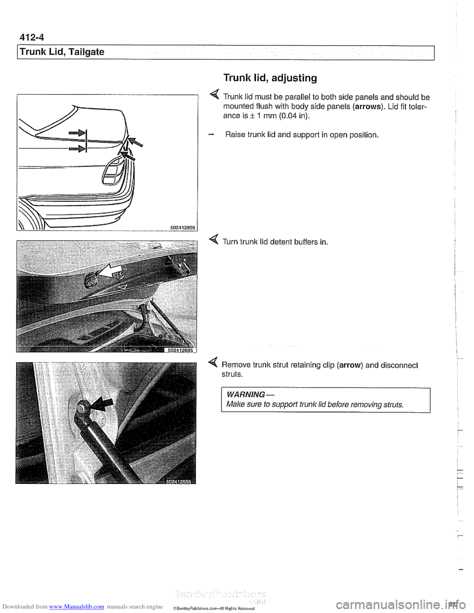
< Trunk lid must be parallel to both side panels and should be
mounted flush with body side panels
(arrows). Lid fit toler-
ance is
rt 1 mm (0.04 in).
- Raise trunlc lid and support in open position.
Turn trunk lid detent buffers in
4 Remove trunlc strut retaining clip (arrow) and disconnect
struts.
WARNING-
Make sure to suppori trunk lid before removing struts.
Page 847 of 1002
Downloaded from www.Manualslib.com manuals search engine
Trunk Lid, Tailgate
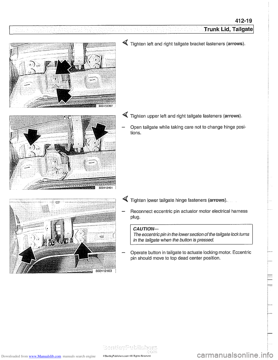
4 Tighten left and right tailgate bracket iasteners (arrows)
4 Tighten upper left and right tailgate fasteners (arrows).
- Open tailgate while taking care not to change hinge posi-
tions.
4 Tighten lower tailgate hinge fasteners (arrows)
- Reconnect eccentric pin actuator motor electrical harness
Plug.
CAUTION-
The eccentric pin in the lowersection of the tailgate loclc turns
in the tailgate when the button is pressed.
- Operate button in tailgate to actuate loclting motor. Eccentric
pin should move to top dead center position.
Page 850 of 1002
Downloaded from www.Manualslib.com manuals search engine
41 2-22
1 Trunk Lid, Tailgate
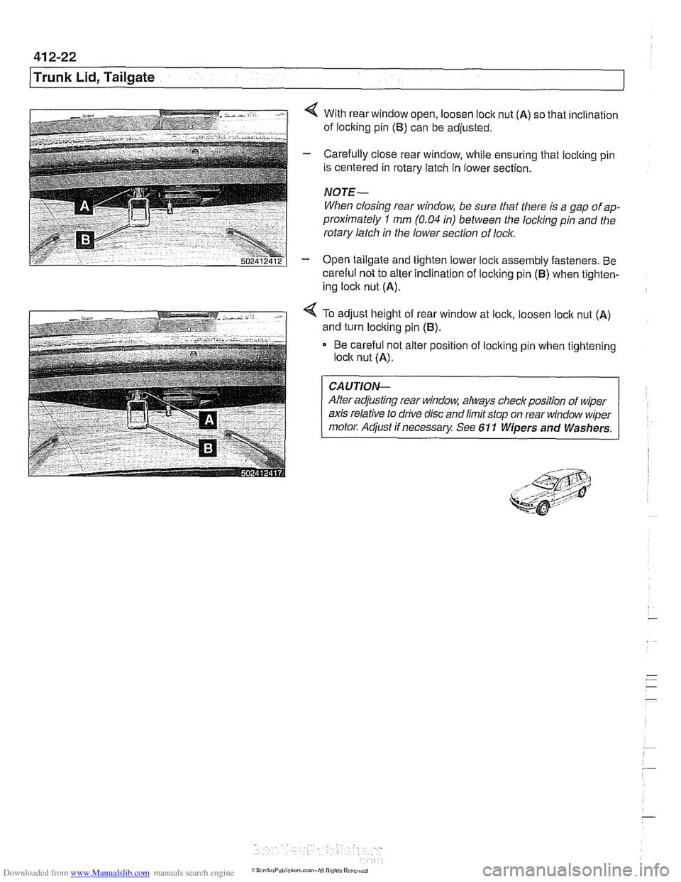
4 With rear window open, loosen loclc nut (A) so that inclination
of loclting pin
(B) can be adjusted.
- Carefully close rear window, while ensuring that locking pin
is centered in rotary latch in lower section.
NOTE-
When closing rear window, be sure that there is a gap of ap-
proximately
1 mm (0.04 in) between the locliing pin and the
rotary latch in the lower section of lock.
- Open tailgate and tighten lower loclc assembly fasteners. Be
careful not to alter inclination of loclting pin
(B) when tighten-
ing loclc nut
(A).
4 To adjust height of rear window at lock, loosen loclc nut (A)
and turn locking pin (B).
Be careful not alter position of loclting pin when tightening
lock nut
(A).
CA UTIOG
After adjusting rear window, always checlr position of wiper
axis relative to drive disc and limit stop on rear window wiper
motor. Adjust if necessary See 611 Wipers and Washers.
Page 853 of 1002
Downloaded from www.Manualslib.com manuals search engine
-.- -
Exterior Trim, Bumpers
Outside mirror glass with automatic dip control,
replacing
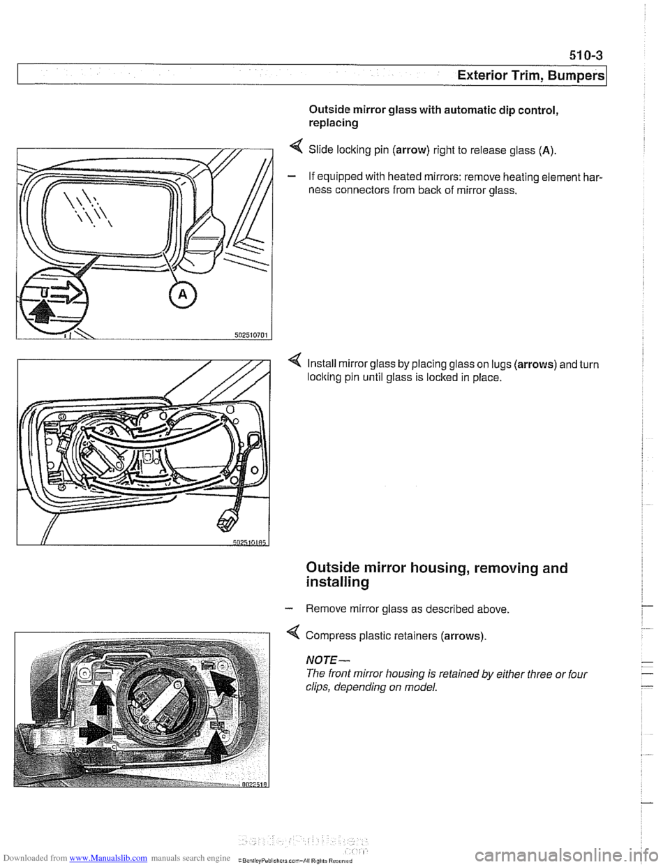
4 Slide locking pin (arrow) right to release glass (A).
- If equipped with heated mirrors: remove heating element har-
ness connectors from
back of mirror glass.
4 Install mirror glass by placing glass on lugs (arrows) and turn
loclting pin until glass is locked in place.
Outside mirror housing, removing and
installing
- Remove mirror glass as described above.
4 Compress plastic retainers (arrows)
NOTE-
The front mirror housing is retained by either three or four
clips, depending on model.
Page 862 of 1002
Downloaded from www.Manualslib.com manuals search engine
I Exterior Trim, Bumpers
Tightening torques Impact absorber to chassis
(M8 nut) 20 Nm (15 ft-lb)
Impact absorber to chassis
(M6 nut) 9 Nm (80 In-lb
Bumper bracket to impact absorber 45 Nm (32 ft-lb)
(MI0 bolt)
Front bumper height, adjusting
- A 14 mm allen socket is needed to make adjustments
- Raise and properly support vehicle.
WARNING-
Make sure that the car is firmly supported on jackstands de-
signed for the purpose. Place the jack stands beneath a
structural chassis point.
Do not place jack stands under sus-
pension parts.
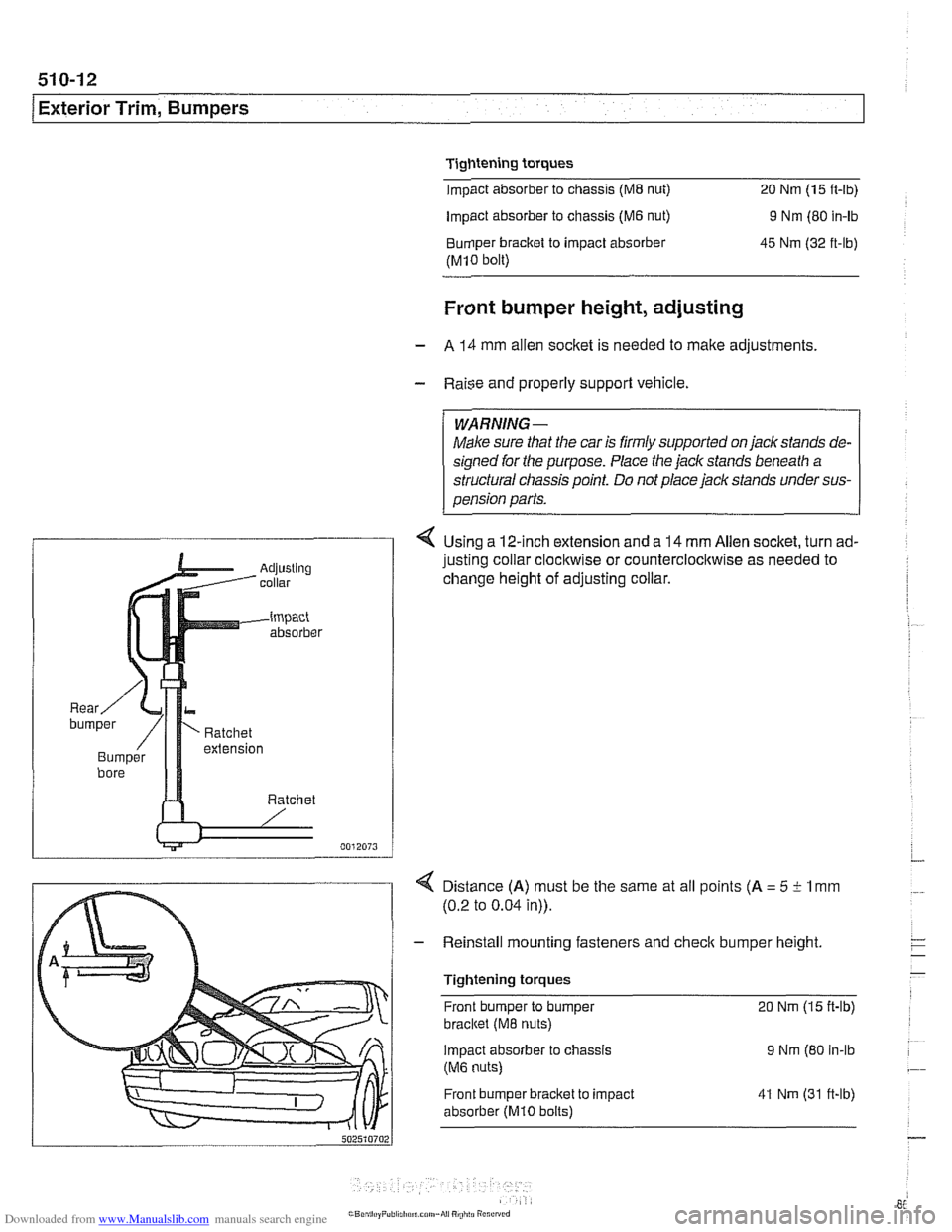
4 Using a 12-inch extension and a 14 mm Allen socket, turn ad-
justing collar
clocl~wise or counterclocl~wise as needed to
change height of adjusting collar.
4 Distance (A) must be the same at all points (A = 5 i- 1 mm
(0.2 to 0.04 in)).
- Reinstall mounting fasteners and check bumper height
Tightening torques Front bumper to bumper
20 Nm (15 ft-lb)
bracltet (M8 nuts)
Impact absorber
to chassis 9 Nm (80 in-lb
(M6 nuts)
Front bumper bracket to impact
absorber
(MI0 bolts)
41 Nm (31 ft-lb)
Page 886 of 1002
Downloaded from www.Manualslib.com manuals search engine
I Interior Trim
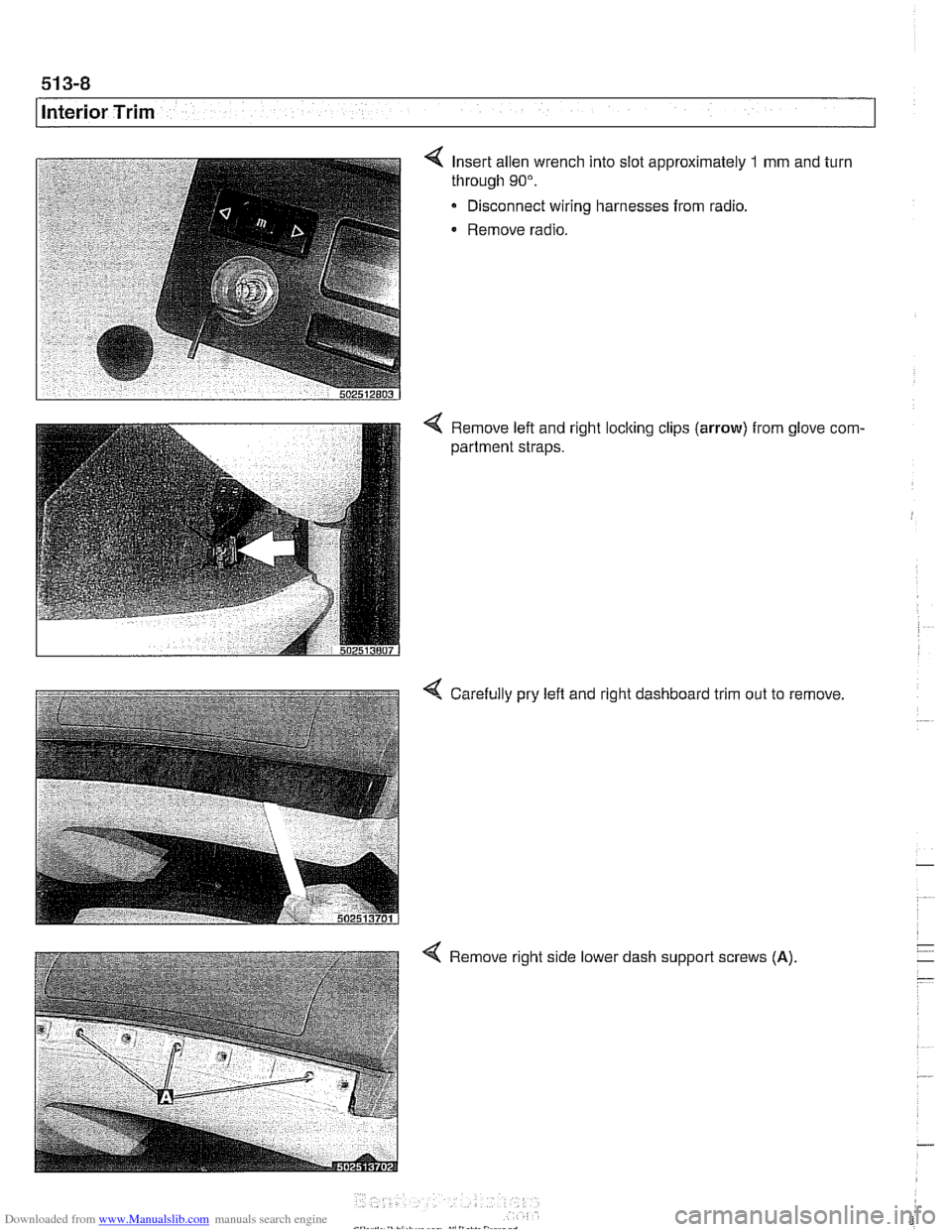
Insert allen wrench into slot approximately 1 mm and turn
through
90".
Disconnect wiring harnesses from radio.
Remove radio.
4 Remove left and right locking clips (arrow) from glove com-
partment straps.
4 Carefully pry left and right dashboard trim out to remove
4 Remove right side lower dash support screws (A)
Page 905 of 1002
Downloaded from www.Manualslib.com manuals search engine
515-11
Central Lockinq and ~nti-l heft/
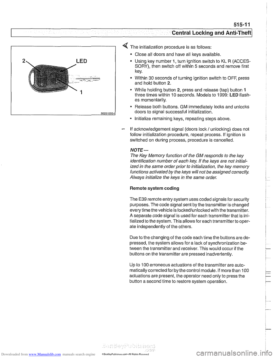
4 The initialization procedure is as follows:
Close ail doors and have all keys available
2 LED Using lkey number I, turn ignition switch to KL R (ACCES-
SORY), then switch off within 5 seconds and remove first
key.
. - -- , ..-.---- - Within 30 seconds of turning ignition switch to OFF, press
and hold button
2.
1 While holding button 2, press and release (tap) button 1
three times within 10 seconds. Models to 1999: LED flash-
- If acknowledgement signal (doors lock / unlocking) does not
follow initialization procedure, repeat process. If ignition is
switched on during process, procedure is cancelled.
50251509‘1
NOTE-
The Key Memory function of the GM responds to the ley
identification number of each key If the keys are not initial-
ized
in the same orderprior to initialization, the ley memory
functions activated by the
l(eys will not be assigned correctly.
Always initialize the keys
in the same order.
es momentarily.
Release both buttons. GM immediately locks and unlocits
doors to signal successful initialization.
Remote system coding
* Initialize remaining lteys, repeating steps above.
The E39 remote entry system uses coded signals for security
purposes. The code signal sent by the transmitter is changed
every time the vehicle is lockedlunlocked with the transmitter.
A separate code signal is used for each transmitter that is ini-
tialized to the system. This allows for each transmitterto oper-
ate independently of the others.
Due to the changing of the code each time the buttons are de-
pressed, the system allows for a
lacit of synchronization be-
tween the transmitter and receiver. This would occur
if the
buttons on the transmitter are pressed inadvertently.
Up to
100 erroneous actuations of the transmitter are auto-
matically corrected
forby the control module. If more than 100
actuations are present, the operator need only to press the
button a second time to restore system operation.
Page 907 of 1002
Downloaded from www.Manualslib.com manuals search engine
- -
Central Locking and ~nti-~hefil
Key Memory
Whenever one of the FZV keys is used to lock or unlock the
car, the user is identified by the GM. A maximum of four
keys
can be programmed with the Key Memoryfeature. The use of
the personalized key then triggers Car Memory functions
such as heating
I AIC (IHKA) settings or memory seat position
adjustment.
Most programming of Key Memory requires the use of
BMW
scan tools (DISplus, GT1 or MoDiC). However, features such
as
IHKA blower speed and temperature store automatically
without the use of scan tools.
Available Key Memory functions vary based on vehicle equip-
ment. The functions that can be set include:
Automatic locking after start off (vehicle speed)
Selective locking
Heating
1 AJC blower speed, heated or cooled air distribu-
tion, automatic blower setting
Trunk lid soft close (SCA)
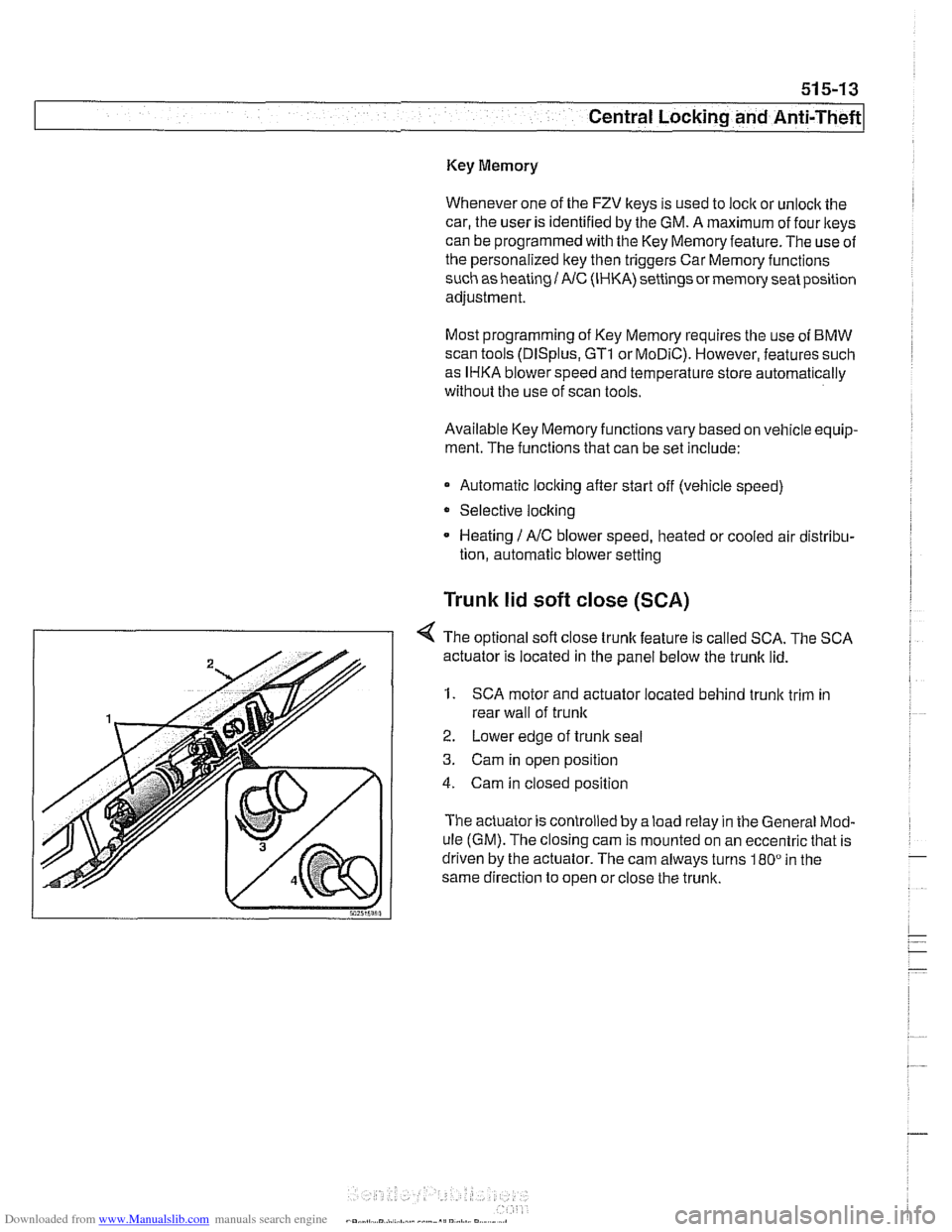
< The optional sofl close trunk feature is called SCA. The SCA
actuator is located in the panel below the trunk lid.
1. SCA motor and actuator located behind trunk trim in
rear wall of
trunlc
2. Lower edge of trunlc seal
3. Cam in open position
4. Cam in closed position
The actuator is controlled by a load relay in the General Mod-
ule (GM). The closing cam is mounted on an eccentric that is
driven by the actuator. The cam always turns
180" in the
same direction to open or close the trunk.