turn BMW 540i 1999 E39 Workshop Manual
[x] Cancel search | Manufacturer: BMW, Model Year: 1999, Model line: 540i, Model: BMW 540i 1999 E39Pages: 1002
Page 483 of 1002
Downloaded from www.Manualslib.com manuals search engine
Fuel Tank and Fuel Pump
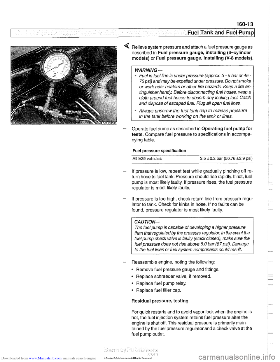
4 Relieve system pressure and attach a fuel pressure gauge as
described in Fuel pressure gauge, installing (6-cylinder
models) or Fuel pressure gauge, installing
(V-8 models).
WARNING-
Fuel in fuel line is under pressure (approx. 3 - 5 bar or 45 -
75psi) and may be expelled underpressure. Do not smoke
or
worlc near heaters or other fire hazards. Keep a fire ex-
tinguisher handy Before disconnecting fuel hoses, wrap a
cloth around fuel hoses to absorb any
leaking fuel. Catch
and dispose of escaped fuel. Plug all open fuel lines.
Always unscrew the fuel tank cap to release pressure
in the tank before
working on the tank or lines.
- Operate fuel pump as described in Operating fuel pump for
tests. Compare fuel pressure to specifications in accompa-
nying table.
Fuel pressure specification
All E39 vehicles 3.5 +0.2 bar (50.76 i2.9 psi)
- If pressure is low, repeat test while gradually pinching off re-
turn hose to fuel tank. Pressure should rise rapidly. If not, fuel
pump is most likely faulty. If pressure rises, the fuel pressure
regulator is most
likely faulty.
- If pressure is too high, checlc return line from pressure regu-
lator to tank. Check for
ltinks in hose. If no faults can be
found, pressure regulator is most likely faulty.
CAUTION-
The fuel pump is capable of developing a higher pressure
than that regulated by the pressure regulator. In the event the
fuel pump checlc valve is faulty (stuck closed), male sure the
I fuel pressure does not rise above 6.0 bar (87psi). Damage
to the fuel lines or fuel system components could result.
- Reassemble engine, noting the following:
Remove fuel pressure gauge and fittings.
Replace schraeder valve, if removed
Replace fuel pump relay.
Replace fuel filler cap.
Residual pressure, testing
For quick restarts and to avoid vapor lock when the engine is
hot, the fuel injection system retains fuel pressure after the
engine is shut off. This residual pressure is primarily
rnain-
tained by the fuel pressure regulator and a checlc valve at the
fuel pump
outlet.
Page 491 of 1002
Downloaded from www.Manualslib.com manuals search engine
Fuel Tank and Fuel pump/
- Remove suction hose from tank filler neck carefully to avoid
damaging filler neck baffle plate.
CAUTION-
After finishing repairs but before starling engine, be sure
there is at least
5 liters (1.5 gallons) of fuel in tanlc. The fuel
pump will be damaged if run without fuel.
Fuel tank, removing and installing
- Remove fuel tank filler cap and drain tank as described
earlier.
- Disconnect negative cable from battery.
CAUTION-
Prior to disconnecting the battea read the battery discon-
nection cautions given in
001 General Cautions and
Warnings.
- Remove rear seat bottom cushion. Peel forward lip of carpet
from beneath seat cushion and carefully peel back insulation
to expose fuel tank access cover on left and right sides. Re-
move covers.
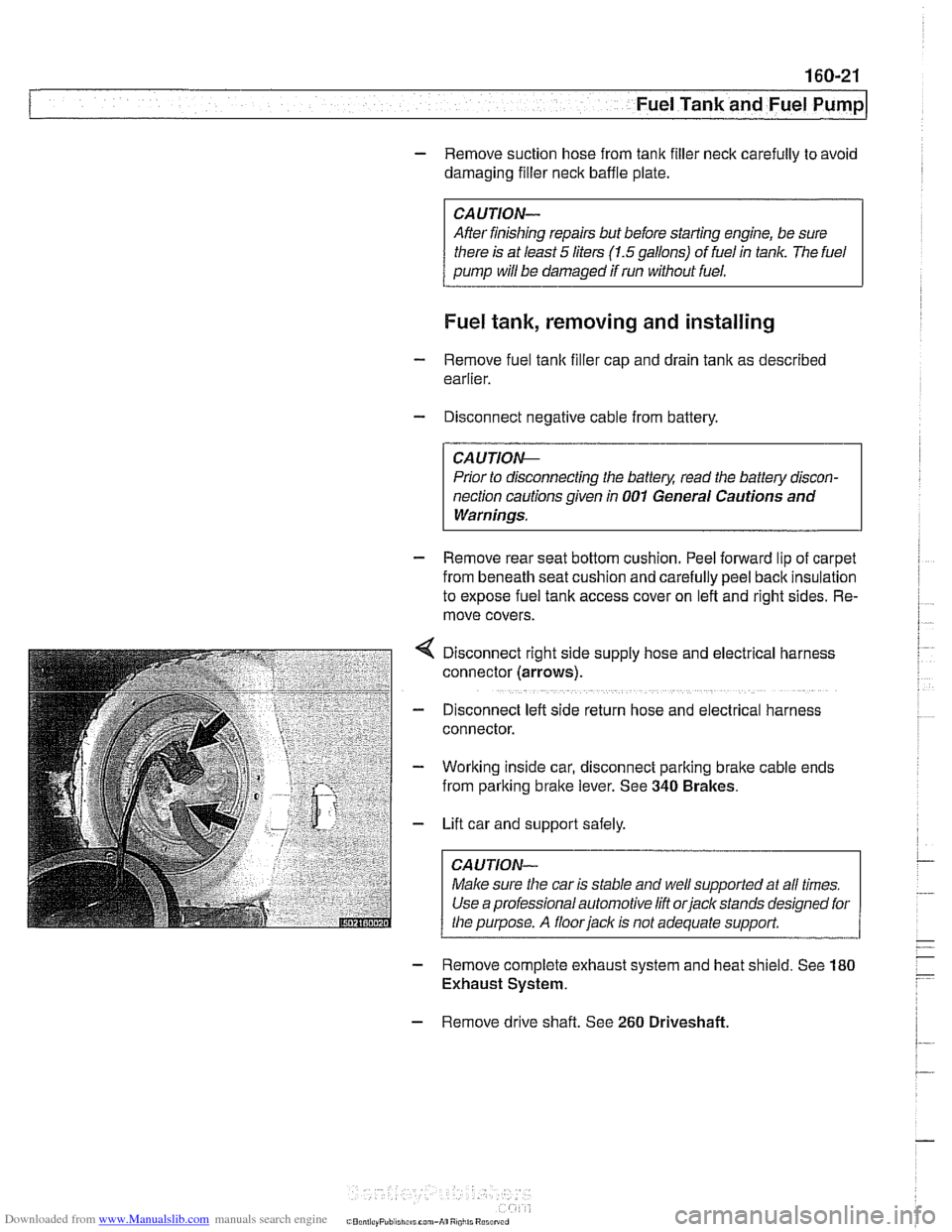
Disconnect right side supply hose and
electr~cal harness
connector (arrows).
D~sconnect left side return hose and electrical harness
connector.
Working inside car, disconnect parking
bralte cable ends
from parking brake lever. See
340 Brakes.
Lift car and support safely.
Make sure the car is stable and
we/ supported at all times.
Use a professional automotive lift
orjack stands designed for
the purpose. A floorjaclc is not adequate support.
- Remove complete exhaust system and heat shield. See 180
Exhaust System.
- Remove drive shaft. See 260 Driveshaft
Page 492 of 1002
Downloaded from www.Manualslib.com manuals search engine
160-22
Fuel Tank and Fuel Pump
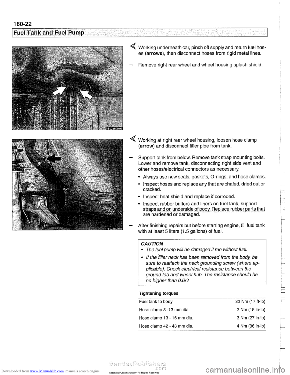
4 Working underneath car, pinch off supply and return fuel hos-
es (arrows), then disconnect hoses from rigid metal lines.
- Remove right rear wheel and wheel housing splash shield.
4 Worlting at right rear wheel housing, loosen hose clamp
(arrow) and disconnect filler pipe from tank.
- Support tank from below. Remove tank strap mounting bolts.
Lower and remove tank, disconnecting right side vent and
other
hoses/electrical connectors as necessary.
Always use new seals, gaskets, O-rings, and hose clamps.
lnspect hoses and replace any that are chafed,
dr~ed out or
cracked.
lnspect heat shield and replace if corroded.
Inspect rubber buffers and
hers on fuel tank, support
straps and on underside of body. Replace rubber parts that
are hardened or damaged.
- After finishing repairs but before starting engine, fill fuel tank
with at least
5 liters (1.5 gallons) of fuel.
CAUTlOI+
The fuelpump will be damaged if run without fuel.
* If the filler neck has been removed from the body, be
sure to reattach the
neck grounding screw (where ap-
plicable). Check electrical resistance between the
ground tab and wheel
hub. The resistance should be
no
hiaher than 0.6f2
Tightening torques
Fuel tank to body 23 Nm (17 ft-lb)
Hose clamp
8 -13 mm dia. 2 Nm (18 in-lb)
Hose clamp 13
- 16 mm dia. 3 Nm (27 in-lb)
Hose clamp 42
- 48 mm dia. 4 Nm (36 in-lb)
Page 494 of 1002
Downloaded from www.Manualslib.com manuals search engine
Fuel Tank and Fuel Pump 1
Activated carbon canister I fuel tank leak
detection unit
(LDP or DMTL), removing . . -
and installing
- Raise rear end of car and support safely.
CAUTION-
Make sure the car is stable and well supported at all times.
Use a professional automotive lift
orjack stands designed for
the purpose.
A floor jack is not adequate support.
- Remove left rear wheel and inner fender panel
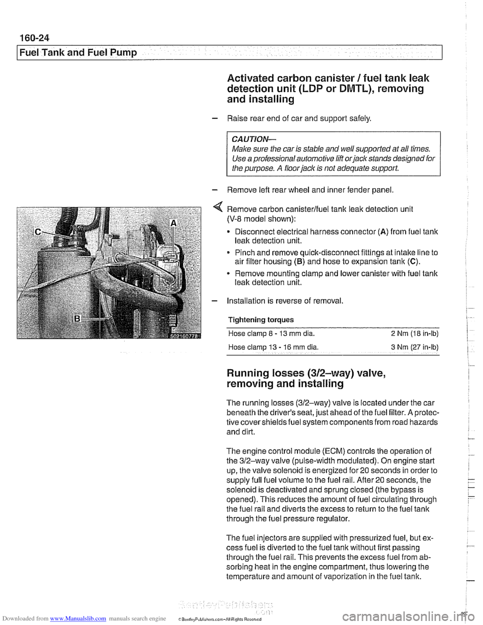
Remove carbon canisterlfuel tank leak detection unit
(V-8 model shown):
Disconnect electrical harness connector
(A) from fuel tank
leak detection unit.
Pinch and remove quick-disconnect fittings at intake line to
air filter housing
(5) and hose to expansion tank (C).
* Remove mounting clamp and lower canister with fuel tank
leak detection unit.
Installation is reverse of removal.
Tightening
torques
Hose clamp 8 - 13 mm dia. 2 Nrn (18 in-lb)
Hose clamp
13 - 16 rnm dia 3 Nm (27 in-lb)
Running losses (312-way) valve,
removing and installing
The running losses (312-way) valve is located under the car
beneath the driver's seat, just ahead of the fuel filter. A protec-
tive covershieldsfuel system components from road hazards
and dirt.
The engine control module
(ECM) controls the operation of
the 312-way valve (pulse-width modulated). On engine start
up, the valve solenoid is energized for 20 seconds in order to
supply full fuel volume to the fuel rail.
After20 seconds, the
solenoid is deactivated and sprung closed (the bypass is
opened). This reduces the amount of fuel circulating through
the fuel rail and diverts the excess to return to the fuel tank
through the fuel pressure regulator.
The fuel injectors are supplied with pressurized fuel, but ex-
cess fuel is diverted to the fuel tank without first passing
through the fuel rail. This prevents the excess fuel from ab-
sorbing heat in the engine compartment, thus lowering the
temperature and amount of vaporization in the fuel tank.
Page 495 of 1002
Downloaded from www.Manualslib.com manuals search engine
160-25
Fuel Tank and Fuel pump1
The 312-way valve is also activated briefly if an engine misfire
is detected. This provides full fuel flow through the fuel rail to
determine if the misfire was caused by a lean fuel condition.
The valve is monitored by the ECM forfaults.
- Using BMW or compatible scan tool, read out fault memory.
See
OBD On-Board Diagnostics.
- Turn off ignition.
- Raise car and support safely.
CA UTIOW
Male sure the car is stable and well suppodedat all times.
Use a professional automotive lift
orjack stands designed for
the purpose.
A floor jack is not adequate support.
- Worlting under car beneath driver's seat, remove protective
panel from fuel filter and 312-way valve.
- Clamp off fuel lines at 312-way valve.
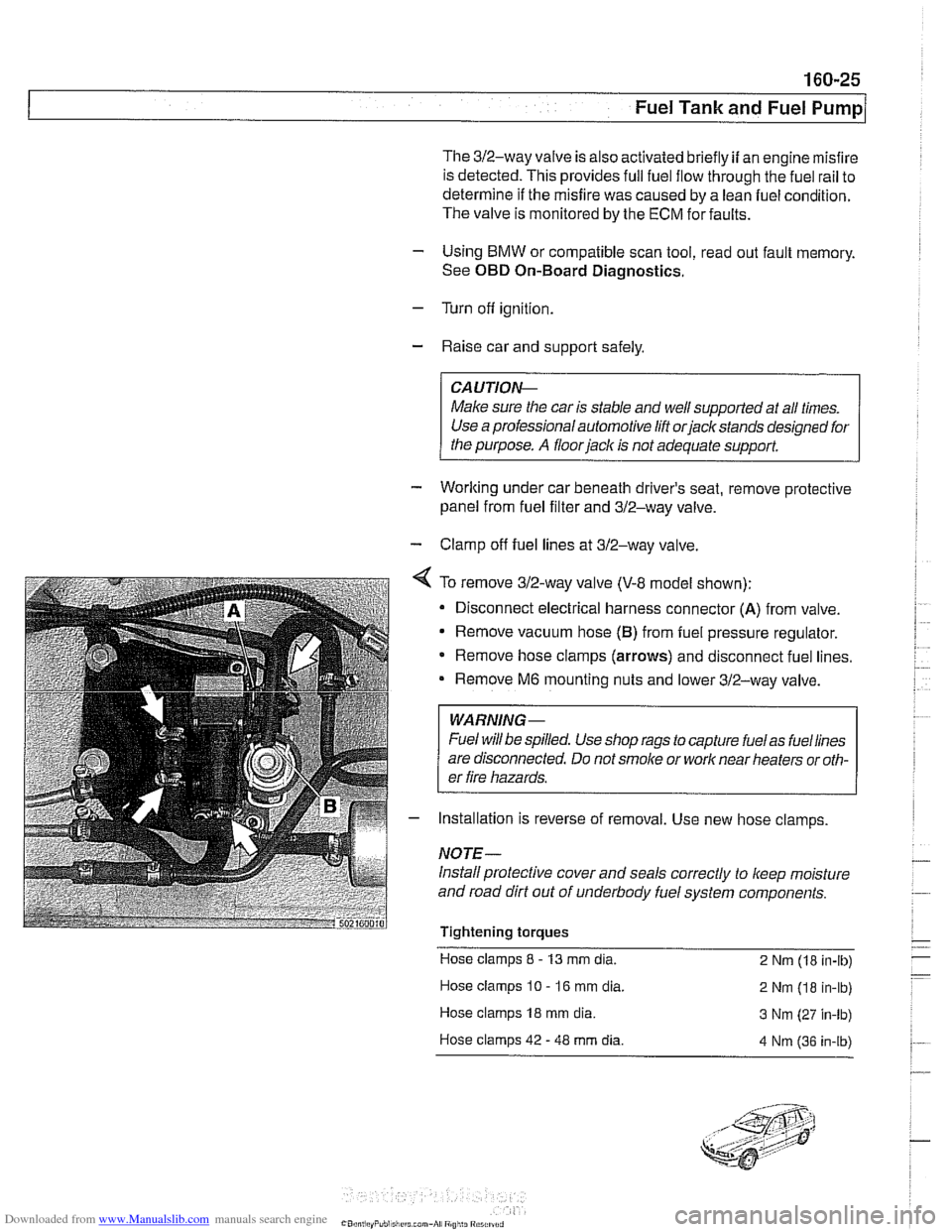
4 To remove 312-way valve (V-8 model shown):
Disconnect electrical harness connector
(A) from valve.
Remove vacuum hose
(B) from fuel pressure regulator.
* Remove hose clamps (arrows) and disconnect fuel lines.
Remove
M6 mounting nuts and lower 312-way valve.
WARNING-
Fuel will be spilled. Use shop rags to capture fuelas fuellines
are disconnected. Do not
smoke or work near heaters or oth-
er fire hazards.
- Installation is reverse of removal. Use new hose clamps
NOTE-
Install protective cover and seals correctly to keep moisture
and road dirt out of underbody fuel system components.
Tightening torques Hose clamps
8 - 13 mm dia.
2 Nm (18 in-lb)
Hose clamps
10 - 16 mm dia.
2 Nm (18 in-lb)
Hose clamps
18 mm dia. 3 Nm (27 in-lb)
Hose clamps 42
- 48 mm dia. 4 Nm 136 in-ib)
Page 501 of 1002
Downloaded from www.Manualslib.com manuals search engine
170-5
Radiator and Cooling System
Fan switch calibration (M52, M62 engine)
coniprairoi OUt rlgnal
Auto. ciimilte ~ontioi inpuls via CAN bus
Electric fan activation:
Low speed
91°C (196°F)
High speed 104' C (21 9' F)
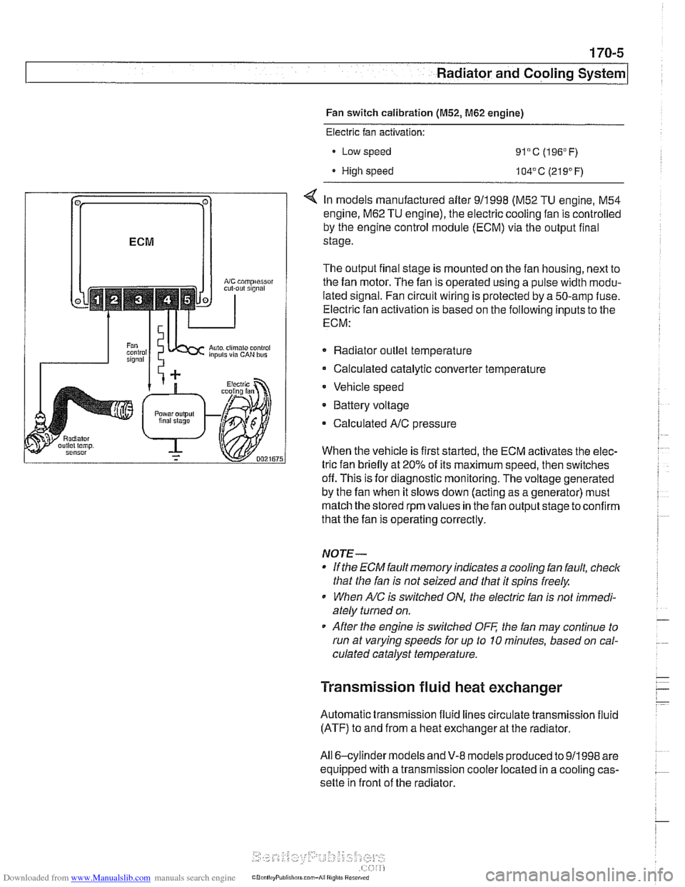
< In models manufactured after 911998 (M52 TU engine, M54
engine.
M62 TU engine), the electric cooling fan is controlled
by the engine control module (ECM) via the output final
stage.
The output final stage is mounted on the fan housing, next to
the fan motor. The fan is operated using a pulse width modu-
lated signal. Fan circuit wiring is protected by a 50-amp fuse.
Electric fan activation is based on the following inputs to the
ECM:
Radiator outlet temperature
Calculated catalytic converter temperature
Vehicle speed
* Battery voltage
Calculated
A/C pressure
When the vehicle is first started, the ECM activates the elec-
tric fan briefly at 20% of its maximum speed, then switches
off. This is for diagnostic monitoring. The voltage generated
by the fan when it slows down (acting as a generator) must
match the stored rpm values in the fan output stage toconfirm
that the fan is operating correctly.
NOTE-
If the ECM fault memory indicates a cooling fan fault, check
that the fan is not seized and that it spins freely.
When
A/C is switched ON, the electric fan is not immedi-
ately turned on.
After the engine is switched
OFF the fan may continue to
run at varying speeds for up to 10 minutes, based on cal-
culated catalyst temperature.
Transmission fluid heat exchanger
Automatic transmission fluid lines circulate transmission fluid
(ATF) to and from a heat exchanger at the radiator.
All 6-cylinder
models andV-8 models produced to 911998 are
equipped with a transmission cooler located in a cooling cas-
sette in front of the radiator.
Page 503 of 1002
Downloaded from www.Manualslib.com manuals search engine
Warnings and cautions
Obse~e the following warnings and cautions when worlting
on the cooling system.
WARNING -
. At normal operating temperature the cooling system is
pressurized. Allow the system to cool as long as possible
before opening (a minimum of one hour), then release the
cap slowly to allow safe release ofpressure.
a Releasing the coolant system pressure lowers the cool-
ant boilingpoint and the coolant may boil suddenly. Use
1 heavy and wear eye and face protection to
guard against scalding.
Use extreme care when draining and disposing of en-
gine coolant. Coolant is poisonous and lethal to hu-
mans andpets. Pets are attracted to coolant because
of its sweet smell and taste. Seek medical attention im-
mediately if coolant is ingested.
CAUTIOG
Avoid adding cold water to the coolant while the engine is
hot or overheated. If it is necessary to add coolant to a
hol
system, do so only with the engine running and coolanl
pump turning.
To avoid excess silicate gel precipitation in the cooling
system and loss of cooling capacity, use BMW coolant
or equivalent low silicate antifreeze.
a If oil enters the cooling system, the radiator, expansion
tank and heating circuit must be flushed with cleaning
agent. BMW recommends removal of the radiator and
expansion
tank to flush.
When
worlcing on the cooling system, cover the alter-
nator to protect it against coolant drips.
Prior to disconnecting the battery, read the battery dis-
connection cautions given in
001 General Warnings
and Cautions.
Begin the diagnosis of cooling system problems with a thor-
ough visual inspection.
If no visual faults are found, it is rec-
ommend that the engine control module (ECM) fault memory
be checked for stored diagnostic trouble codes
(DTCs) using
BMW scan tool
DlSplus or equivalent.
Page 510 of 1002
Downloaded from www.Manualslib.com manuals search engine
Radiator and Cooling System
Cooling system, bleeding
Trapped air in the cooling system can prevent proper coolant
circulation and overheating. Wheneverthe coolant is drained
and filled, bleed the cooling system to remove trapped air.
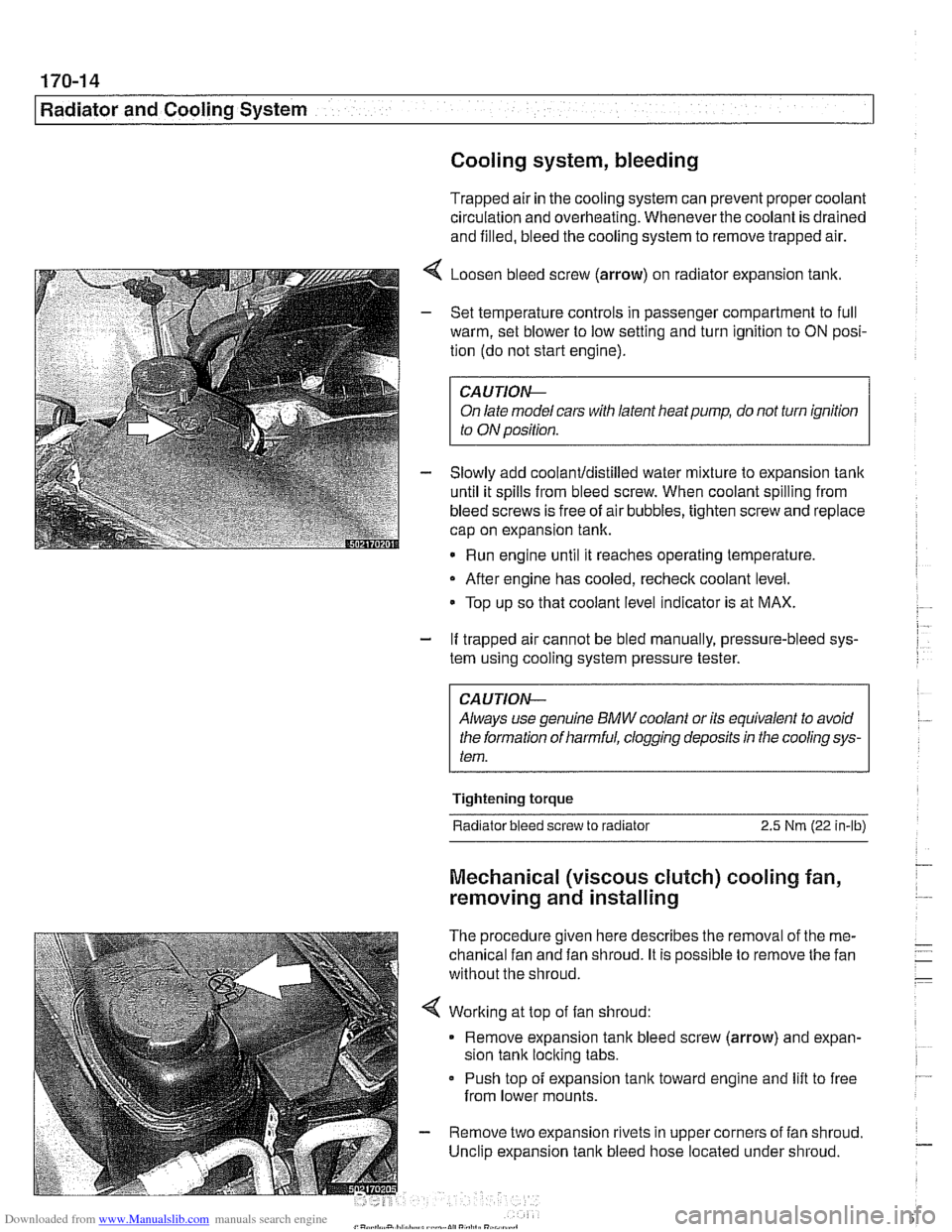
4 Loosen bleed screw (arrow) on radiator expansion tank.
- Set temperature controls in passenger compartment to full
warm, set blower to low setting and turn ignition to
ON posi-
tion (do not start engine).
CAUTIOIG
On late model cars with latent heat pump, do not turn ignition
to ON position.
- Slowly add coolanUdistilled water mixture to expansion tank
until it spills from bleed screw. When coolant spilling from
bleed screws is free of air bubbles, tighten screw and replace
cap on expansion tank.
Run engine until it reaches operating temperature,
- After engine has cooled, recheck coolant level.
Top up so that coolant level indicator is at MAX.
- If trapped air cannot be bled manually, pressure-bleed sys-
tem using cooling system pressure tester.
CA UTlON--
Always use genuine BMW coolant or its equivalent to avoid
the formation of harmful, clogging deposits
in the cooling sys-
tem.
Tightening torque
Radiator bleed screw to radiator 2.5 Nm (22 in-lb)
Mechanical (viscous clutch) cooling fan,
removing and installing
The procedure given here describes the removal of the me-
chanical fan and fan shroud. It is possible to remove the fan
without the shroud.
< Working at top of fan shroud:
Remove expansion tank bleed screw (arrow) and expan-
sion tank locking tabs.
Push top of expansion
tank toward engine and lift to free
from lower mounts.
- Remove two expansion rivets in upper corners of fan shroud.
Unclip expansion tank bleed hose located under shroud.
Page 511 of 1002
Downloaded from www.Manualslib.com manuals search engine
Radiator and Cooling System
Remove rubber trim strip between top of shroud and radiator.
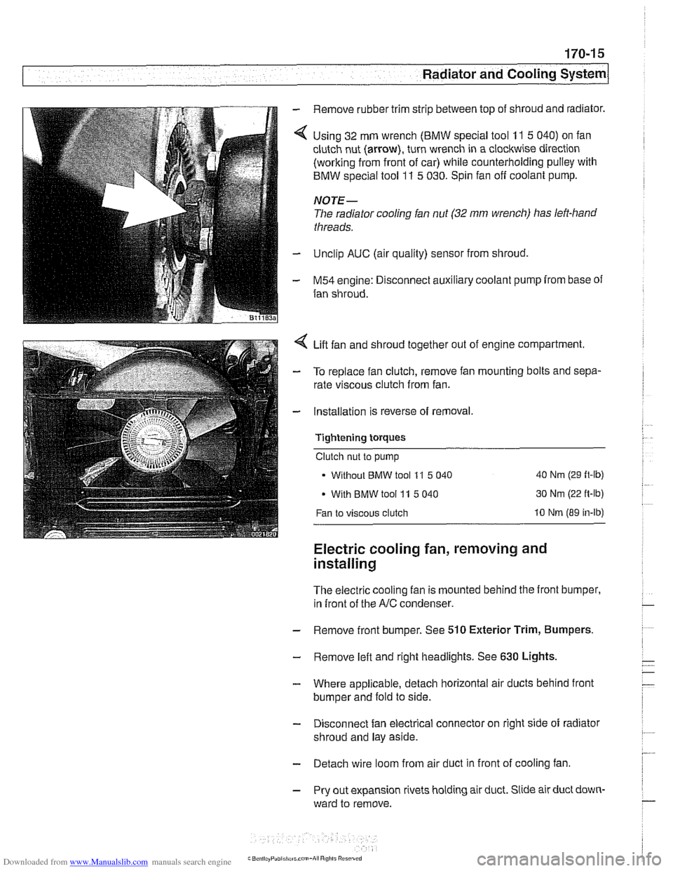
Using 32 mm wrench
(BMW special tool 11 5 040) on fan
clutch nut (arrow), turn wrench in a clockwise direction
(working from front of car) while counterholding pulley with
BMW special tool
11 5 030. Spin fan off coolant pump.
NOTE-
The radiator cooling fan nut (32 mm wrench) has left-hand
threads.
Unclip AUC (air quality) sensor from shroud,
M54 engine: Disconnect auxiliary coolant pump from base of
fan shroud.
Lift fan and shroud together out of engine compartment.
To replace fan clutch, remove fan mounting bolts and sepa-
rate viscous clutch from fan.
Installation is reverse of removal.
Tightening
torques
Clutch nut to pump
Without
BMW tool 11 5 040 40 Nm (29 ft-lb)
With BMW tool 11 5 040 30 Nm
(22 ft-lb)
Fan to viscous clutch 10 Nm (89 in-lb)
Electric cooling fan, removing and
installing
The electric cooling fan is mounted behind the front bumper,
in front of the
A/C condenser.
- Remove front bumper. See 510 Exterior Trim, Bumpers.
- Remove left and right headlights. See 630 Lights,
- Where applicable, detach horizontal air ducts behind front
bumper and fold to side.
- Disconnect fan electrical connector on right side of radiator
shroud and lay aside.
- Detach wire loom from air duct in front of cooling fan
- Pry out expansion rivets holding air duct. Slide air duct down-
ward to remove.
Page 519 of 1002
Downloaded from www.Manualslib.com manuals search engine
. --
Radiator and Cooling system/
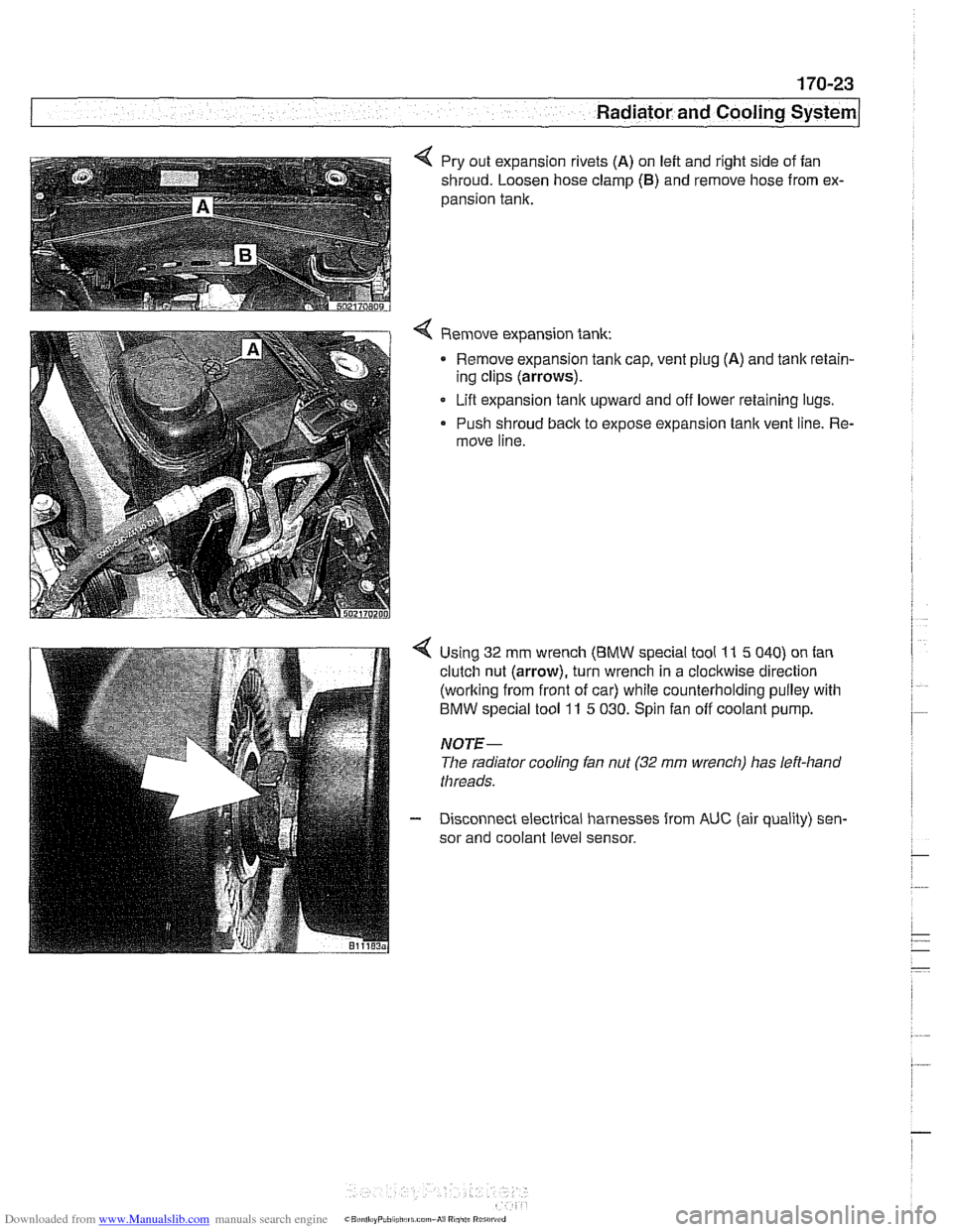
4 Pry out expansion rivets (A) on left and right side of fan
shroud. Loosen hose clamp
(6) and remove hose from ex-
pansion tank.
Remove expansion tank: Remove expansion tanlc cap, vent plug
(A) and tank retain-
ing clips (arrows).
Lift expansion
tanlc upward and off lower retaining lugs.
Push shroud back to expose expansion tank vent line. Re-
move line.
Using 32 mm wrench
(BMW special tool 11 5 040) on fan
clutch nut (arrow), turn wrench in a clockwise direction
(working from front of car) while counterholding pulley with
BMW special tool 11 5 030. Spin fan off coolant pump.
NOTE-
The radiator cooling fan nut (32 mrn wrench) has left-hand
threads.
Disconnect electrical harnesses from
AUC (air quality) sen-
sor and coolant level sensor.