turn BMW 540i 1999 E39 Workshop Manual
[x] Cancel search | Manufacturer: BMW, Model Year: 1999, Model line: 540i, Model: BMW 540i 1999 E39Pages: 1002
Page 558 of 1002
Downloaded from www.Manualslib.com manuals search engine
21 0-1 6
Clutch
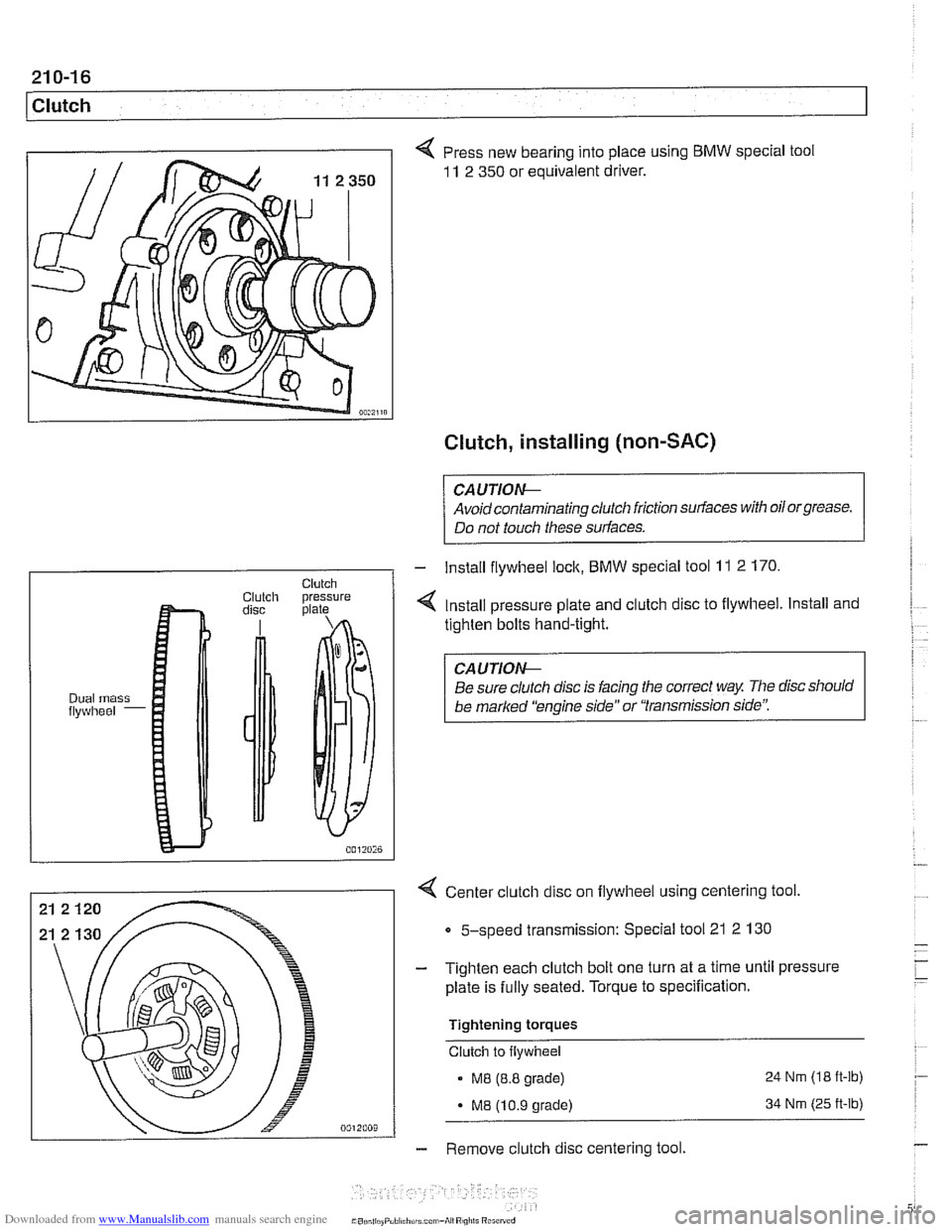
4 Press new bearing into place using BMW special tool
11 2 350 or equivalent driver.
Clutch, installing (non-SAC)
CAUTIOG
Avoidcontaminating clutch friction surfaces with oilorgrease.
Do not touch these surfaces.
4 Center clutch disc on flywheel using centering tool
Clutch Clutch pressure disc plate
Dual mass flywheel -
5-speed transmission: Special tool 21 2 130
- Install flywheel lock, BMW special tool 11 2 170.
4 Install pressure plate and clutch disc to flywheel. Install and
tighten bolts hand-tight.
CAUTIOG
Be sure clutch disc is facing the correct way The disc should
be
marked 'kngine side" or "transmission side':
- Tighten each clutch bolt one turn at a time until pressure
plate is fully seated. Torque to specification.
Tightening torques
Clutch to flywheel
. M8 (8.8 grade) 24 Nrn (18
ft-lb)
- M8 (10.9 grade) 34 Nrn (25 ft-lb)
- Remove clutch disc centering tool.
Page 560 of 1002
Downloaded from www.Manualslib.com manuals search engine
21 0-1 8
Clutch
- lnstall flywheel lock, special tool 11 2 170 (6 cylinder model)
or
11 2 070 (V-8 model).
- Install SAC pressure plate on dowel pins at flywheel. lnstall
clutch mounting bolts and tighten each one turn at a time until
pressure plate is fully seated. Torque to specification.
Tightening torques Clutch to flywheel
- M8 (8.8 grade)
MB 110.9 orade)
24 Nm (1 8 it-lb)
34 Nm (25
ft-lb)
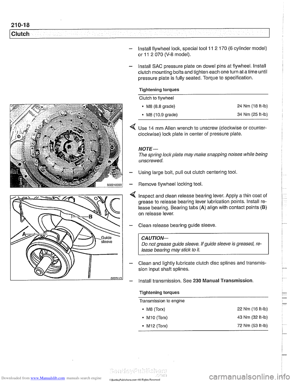
Use 14 mm Allen wrench to unscrew (clocltwise or counter-
clockwise) lock plate in center of pressure plate.
NOTE-
The spring lockplate may make snapping noises while being
unscrewed.
Using large bolt, pull out clutch centering tool
Remove flywheel locking tool
4 Inspect and clean release bearing lever. Apply a thin coat of
grease to release bearing lever lubrication points. lnstall re-
lease bearing. Bearing tabs
(A) align with contact points (B)
on release lever.
- Clean release bearing guide sleeve.
CAUTIOG
Do not grease guide sleeve. Ifguide sleeve is greased, re-
lease bearing may stick to it.
- Clean and lightly lubricate clutch disc splines and transmis-
sion input shaft splines.
- lnstall transmission. See 230 Manual Transmission.
Tightening torques
- - - Transmlsslon to engine -
. MB (Torx) 22
Nm (16 it-lb)
MI0 (Torx) 43 Nm (32 it-lb)
* M12 (Torx) 72 Nm (53 it-lb)
.-
Page 562 of 1002
Downloaded from www.Manualslib.com manuals search engine
1 Clutch
- lnstall flywheel lock, special tool 11 2 170 (6 cylinder model)
or
11 2 070 (V-8 model).
- lnstall SAC pressure plate on dowel pins at flywheel. lnstall
clutch mounting bolts and tighten each one turn at a time until
pressure plate is fully seated. Torque to specification.
Tightening torques
Clutch to flywheel
- M8 (8.8 grade)
M8 (10.9 grade) 24
Nm (18
ft-ib)
34
Nm (25 ft-lb)
- Slip out clutch centering tool using large bolt.
- Remove flywheel locking tool.
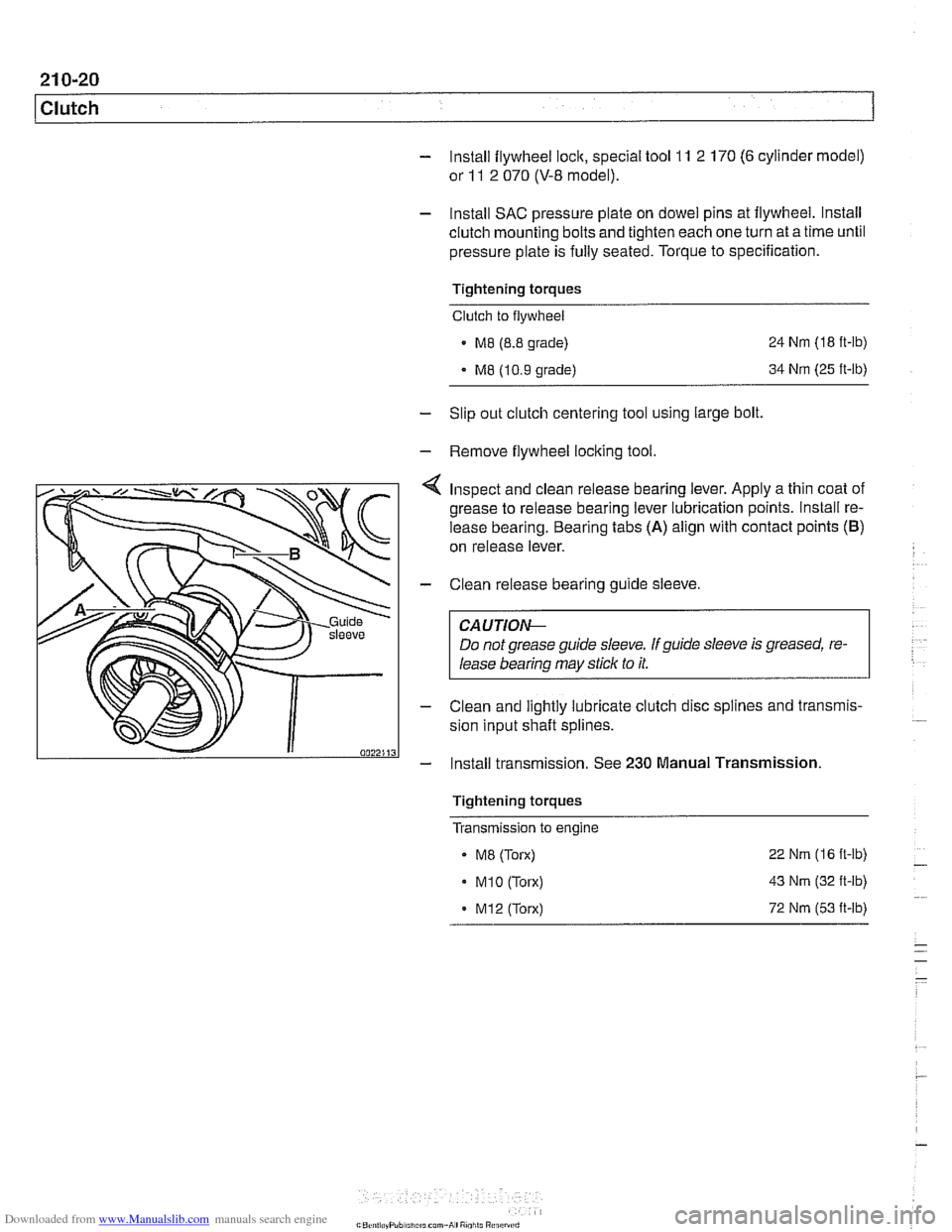
Inspect and clean release bearing lever. Apply a thin coat of
grease to release bearing lever lubrication points. lnstall re-
lease bearing. Bearing tabs
(A) align with contact points (B)
on release lever.
- Clean release bearing guide sleeve.
CA U TIOG
Do not grease guide sleeve. If guide sleeve is greased, re-
lease bearing may stick to it.
- Clean and lightly lubricate clutch disc splines and transmis-
sion input shaft splines.
- Install transmission. See 230 Manual Transmission
Tightening torques
Transmission to engine
- ME (Torx)
. M1O (Torx)
. M12 (Torx) 22
Nm (16 ft-lb)
43
Nm (32 ft-lb)
72
Nm (53 it-lb)
Page 582 of 1002
Downloaded from www.Manualslib.com manuals search engine
230-1 8
Manual Transmission
- Unbolt clutch slave cylinder from side of transmission. Do not
disconnect fluid hose. Suspend slave cylinder from chassis
using stiff wire.
CA UTIOG
Unbolt clutch slave cylinder slowly to prevent air being
drawn into hydraulic system.
. Do not operate clutch pedal with slave cylinder re-
moved from transmission.
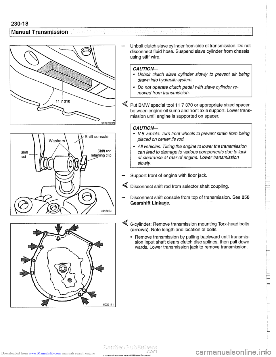
4 Put BMW special tool 11 7 370 or appropriate sized spacer
between engine oil sump and front axle support. Lower trans-
mission until engine is supported on spacer.
0 V-8 vehicle: Turn front wheels to prevent strain from being
placed on center tie rod.
All vehicles: Tilting the engine to lower the transmission
can lead to damage to various components due to lack
of clearance at rear of engine. Lower transmission
slowly
- Support front of engine with floor jack.
4 Disconnect shift rod from selector shaft coupling
- Disconnect shift console from top of transmission. See 250
Gearshift Linkage.
6-cylinder: Remove transrnisslon mounting Torx-head bolts
(arrows). Note length and locatlon of bolts.
Remove
transrnlssion by pulling backward untll transmls-
sion Input shaft clears clutch d~sc spl~nes, then pull down-
wards. Lower
transmlsslon jack to remove transrnlsslon. -
- - -
-
Page 595 of 1002
Downloaded from www.Manualslib.com manuals search engine
Automatic ~ransmissionl
II I
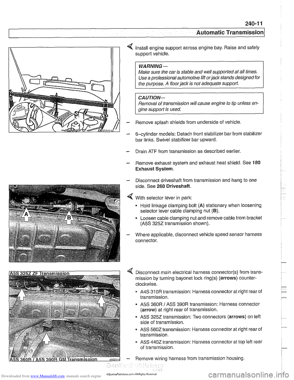
4 Install engine support across engine bay. Raise and safely
support vehicle.
Make sure the car is stable and
we1 supported at all times.
Use a professional automotive lift
orjaclc stands designed for
CAUTIOI\C
Removal of transmission will cause engine to tip unless en-
gine support is used.
- Remove splash shields from underside of vehicle.
- &cylinder models: Detach front stabilizer bar from stabilizer
bar
links. Swivel stabilizer bar upward.
- Drain ATF from transmission as described earlier.
- Remove exhaust system and exhaust heat shield. See 180
Exhaust System.
- Disconnect driveshaft from transmission and hang to one
side. See
260 Driveshaft.
4 With selector lever in park:
Hold
linkage clamping bolt (A) stationary when loosening
selector lever cable clamping nut
(6).
- Loosen cable clamping nut and remove cable from bracket
(ASS
3252 transmission shown).
- Where applicable, disconnect vehicle speed sensor harness
connector.
4 Disconnect main electrical harness connector(s) from trans-
mission by turning bayonet lock
ring(s) (arrows) counter-
clocltwise.
A4S
310R transmission: Harness connector at right rear of
transmission.
ASS
360R / ASS 390R transmission: Harness connector
(arrow) at right rear of transmission.
ASS 3252 transmission: Two connectors (arrows) on left
side of transmission.
ASS 5602 transmission: Harness connector at right rear of
transmission.
- ASS 4402 transmission: Harness connector at top left rear
of transmission.
- Remove wiring harness from transmission housing
Page 596 of 1002
Downloaded from www.Manualslib.com manuals search engine
Automatic Transmission
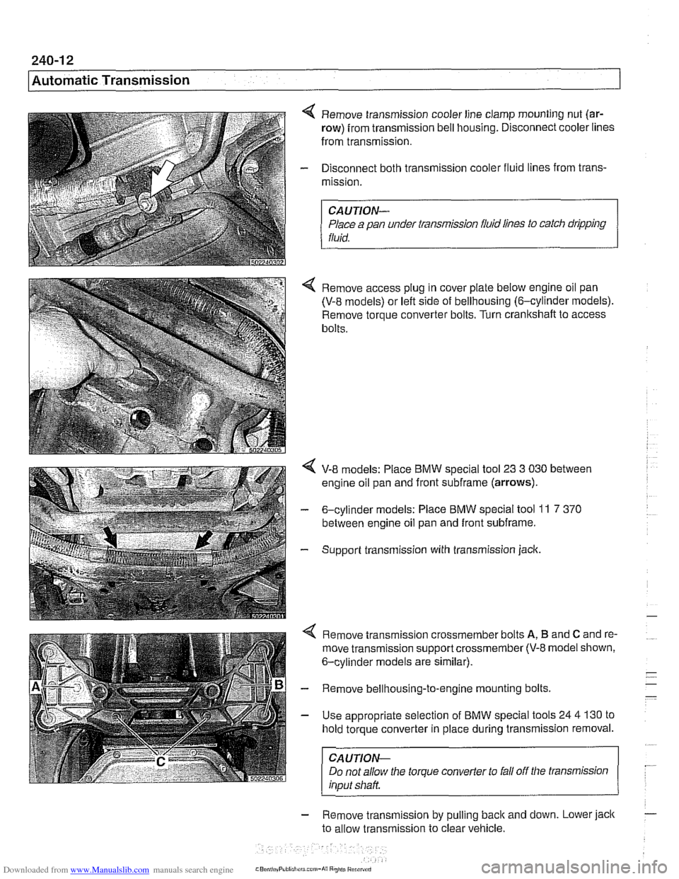
4 Remove transmission cooler line clamp mounting nut (ar-
row) from transmission bell housing. Disconnect cooler lines
from transmission.
- Disconnect both transmission cooler fluid lines from trans-
mission.
CAUTION-
Place a pan under transmission fluid lines to catch dripping
fluid.
4 Remove access plug in cover plate below engine oil pan
(V-8 models) or left side of bellhousing (6-cylinder models).
Remove torque converter bolts. Turn
cranltshaft to access
bolts.
V-8 models: Place BMW special tool 23 3 030 between
engine oil pan and front
subframe (arrows).
- 6-cylinder models: Place BMW special tool 11 7 370
between engine oil pan and front subframe.
- Support transmission with transmission jack.
4 Remove transmission crossmember bolts A, B and C and re-
move transmission support crossmember
(V-8 model shown,
6-cylinder models are similar).
- Remove bellhousing-to-engine mounting bolts.
- Use appropriate selection of BMW special tools 24 4 130 to
hold torque converter in place during transmission removal.
CAUTION-
Do not allow the torque converter to fall off the transmission
input shaft
- Remove transmlsslon by pull~ng back and down. Lower jack
to allow transmiss~on to clear vehicle.
rrs corn-hi8 Rniiti Riranrd
Page 602 of 1002
Downloaded from www.Manualslib.com manuals search engine
250-4
I Gearshift Linkage
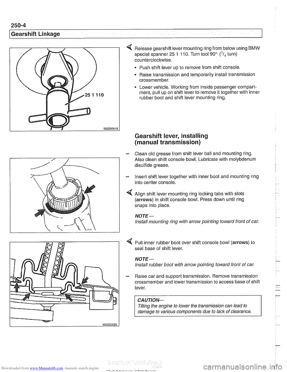
Release gearshift lever mounting ring from below using BMW
special spanner 25 1 110. Turn tool 90' ('I, turn)
counterclockwise.
Push shift lever up to remove from shift console,
Raise transmission and temporarily install transmission
crossmember.
Lower vehicle. Working from inside passenger compart-
ment, pull up on shift lever to remove it together with inner
rubber boot and shift lever mounting ring.
Gearshift lever, installing
(manual transmission)
- Clean old grease from shift lever ball and mounting ring.
Also clean shift console bowl. Lubricate with molybdenum
disulfide grease.
- Insert shift lever together with inner boot and mounting ring
into center console.
4 Align shift lever mounting ring locking tabs with slots
(arrows) in shift console bowl. Press down until ring
snaps into place.
NOTE-
lnstall mounting ring witli arrow pointing toward front of car.
4 Pull inner rubber boot over shift console bowl (arrows) to
seal base of shift lever.
NOTE-
lnstall rubber boot witli arrow pointing toward front of car.
- Raise car and support transmission. Remove transmission
crossmember and lower transmission to access base of shift
lever.
CAUTIOI\C
Tilting the engine to lower the transmission can lead to
damage to various components due to lack of clearance.
Page 606 of 1002
Downloaded from www.Manualslib.com manuals search engine
250-8
Gearshift Linkage
-;Ag Gate "",?it.,
Shift interlock, checking function
(automatic transmission)
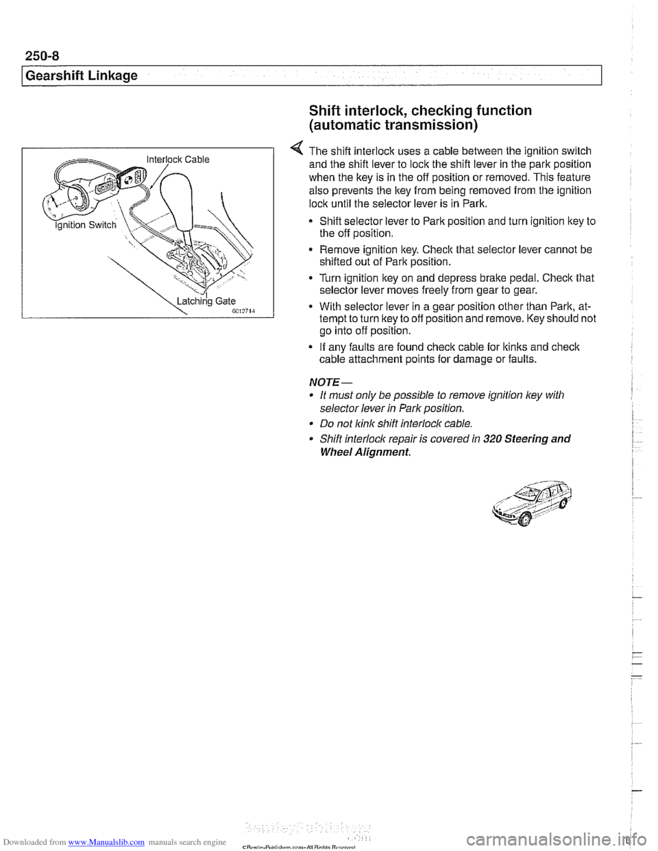
4 The shift interlock uses a cable between the ignition switch
and the shift lever to lock the shift lever in the park position
when the key is in the off position or removed. This feature
also prevents the key
from being removed from the ignition
lock until the selector lever is in Park.
Shift selector lever to Park position and turn ignition key to
the off position.
Remove ignition key. Checlc that selector lever cannot be
shifted out of Park position.
Turn ignition lkey on and depress
brake pedal. Checlc that
selector lever moves freely from gear to gear.
With selector lever in a gear position other than Park, at-
tempt to turn lkey to off position and remove. Key should not
go into off position.
If any faults are found check cable for lkinks and
check
cable attachment points for damage or faults.
NOTE-
* It must only be possible to remove ignition ley with
selector lever
in Park position.
* Do not link shift interlocl( cable.
Shift interlock repair is covered
in 320 Steering and
Wheel Alignment.
Page 616 of 1002
Downloaded from www.Manualslib.com manuals search engine
260-1 0
/ Driveshaft
Driveshaft, installing
- Prepare CV joint for reinstallation:
Extend joint to limit.
Clean off old grease and fill with fresh grease
Install new seal.
- Bend driveshaft slightly at center universal joint to install
CAUTION-
Do not allow CVjoint seal to become displaced.
- Align matchmarlts on driveshaft to matchmarks on final drive
and transmission flanges.
- Fit constant velocity joint to final drive input flange. Alternate-
ly tighten two opposite nuts to draw constant velocity joint
evenly into the final drive input flange. Once seated, tighten
down remaining nuts.
I CAUTION-
I Do not reuse self-locking nuts. These nuts are designed to be /
I used onlv once. 1
- Insert bolts in front of driveshafl to transmission output
flange. Counterhold each bolt while tightening nut.
CAUTION-
. Do not reuse self-locking nuts. These nuts are designed to
be used only once.
Avoid stressing the flex-disc when torquing the bolts.
Do this by counterholding the bolts and turning the nuts
on the flange side.
- Position center support bearing and install mounting nuts.
Use new self-locking nuts.
- Install heat shields.
- Install rear transmission support crossmember.
- Install exhaust system. See 180 Exhaust System.
Reconnect oxygen sensor wiring harnesses and reattach
wiring harness retainers to rear transmission support
crossrnernber.
Page 617 of 1002
Downloaded from www.Manualslib.com manuals search engine
Driveshaft
- Road test vehicle to check for noise or vibration
CAUTION-
Do not reuse self-locking nuts. These nuts are designed to
be used only once.
Avoid stressing the flex-disc when torquing the bolts.
Do this by counterholding the bolts and turning the nuts
on the flange side.
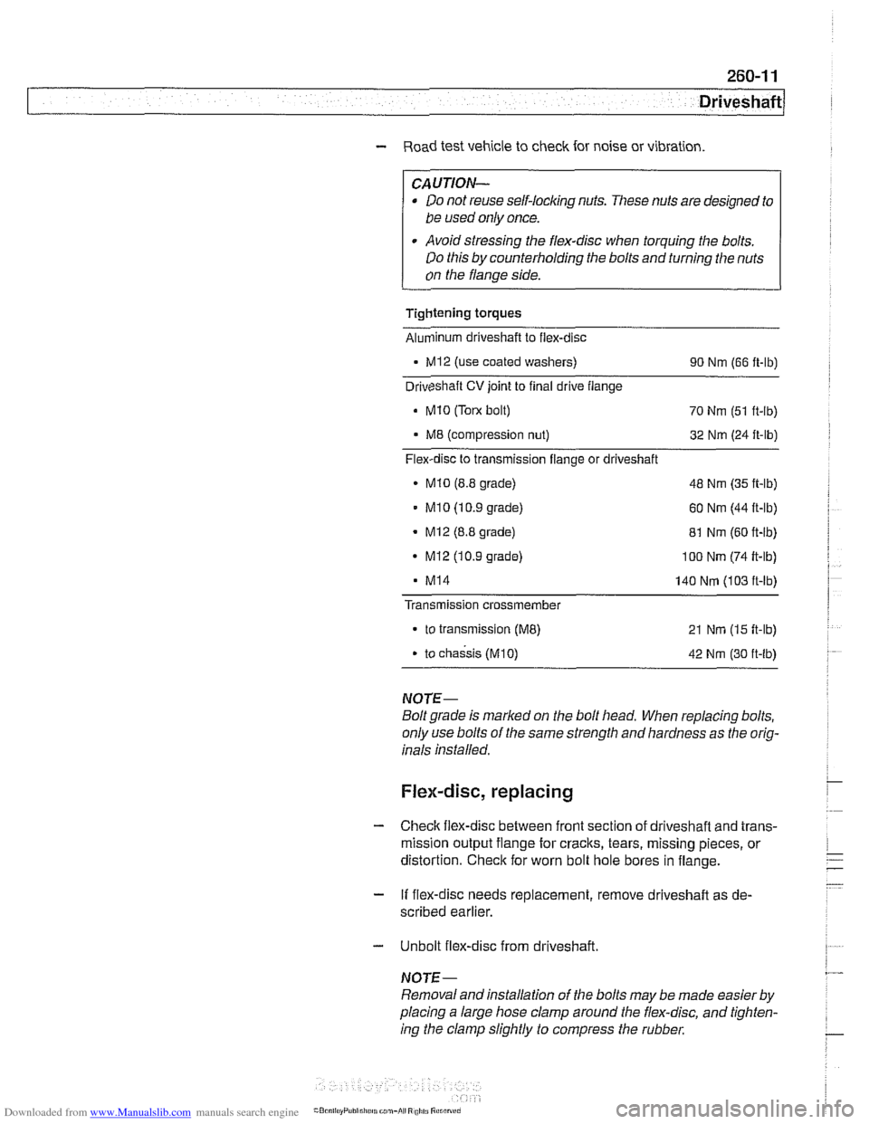
Tightening torques
Alunlinum driveshaft to flex-disc
- MI2 (use coated washers)
90 Nm (66 ft-lb)
Driveshaft
CV joint to final drive flange
Mi0 (Tom bolt)
70 Nm (51 ft-lb)
M8 (compression nut) 32 Nm (24 ft-lb)
Flex-disc to transmission flange or driveshaft
MI0 (8.8 grade) 48 Nm (35 ft-lb)
MI 0 (1 0.9 grade) 60 Nm (44 ft-lb)
- Mi2 (8.8 grade)
81 Nm (60 ft-lb)
- MI2 (10.9 grade) I00 Nm (74 ft-lb)
MI4 140 Nm (103 ft-lb)
Transmission
crossmember
to transmission (ME) 21 Nm (15 ft-lb)
. to chassis (M10) 42 Nm (30 ft-lb)
NOTE-
Boltgrade is marked on the bolt head. When replacing bolts,
only use bolts of the same strength and hardness as the orig-
inals installed.
Flex-disc, replacing
- Checlc flex-disc between front section of driveshafl and trans-
mission output flange for craclts, tears, missing pieces, or
distortion. Check for worn bolt hole bores in flange.
- If flex-disc needs replacement, remove driveshafl as de-
scribed earlier.
- Unbolt flex-disc from driveshaft.
NOTE-
Removal andinstallation of the bolts may be made easier by
placing a large hose clamp around the flex-disc, and tighten-
ing the clamp slightly to compress the rubber.