turn BMW 540i 1999 E39 Workshop Manual
[x] Cancel search | Manufacturer: BMW, Model Year: 1999, Model line: 540i, Model: BMW 540i 1999 E39Pages: 1002
Page 741 of 1002
Downloaded from www.Manualslib.com manuals search engine
-- I
I: ... . -. Rear Suspension! -- .- -
Air compressor pump relay, removing and
installing
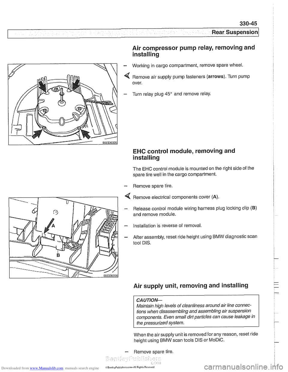
- Working in cargo compartment, remove spare wheel.
4 Remove air supply pump fasteners (arrows). Turn pump
over.
- Turn relay plug 45" and remove relay.
EHC control module, removing and
installing
The EHC control module is mounted on the right side of the
spare tire
well in the cargo compartment.
- Remove spare tire.
4 Remove electrical components cover (A).
- Release control module wiring harness plug loclting clip (B)
and remove module.
- Installation is reverse of removal.
- After assembly, reset ride height using BMW diagnostic scan
tool DIS.
Air supply unit, removing and installing
CAUTION-
Maintain high levels of cleanliness around air line connec-
tions when disassembling and assembling air suspension
components. Even small dirt particles can cause
leakage in
the pressurized system.
When the airsupply unit is removed for any reason, reset ride
height using BMW scan tools DIS or
MoDiC.
- Remove spare tire.
i~B,!n,,ayPubi.l,c~u.c~"~-A~~ R
Page 743 of 1002
Downloaded from www.Manualslib.com manuals search engine
330-47
Rear suspension/
Ride height sensor, removing and installing
Hall effect sensors for vehicle height detection are mounted
on the
left and right sides of the rear suspension. A coupling
rod mounted between the rear suspension arm and the sen-
sor arm is used to send a varying voltage signal to the
EHC
control module.
Raise car and support safely.
WARNING-
Male sure the car is firmly supported on jaclc stands de-
signed
for the purpose. Place jaclc stands underneath struc-
tural chassis points. Do not place jaclc stands under
sus~ension Darts.
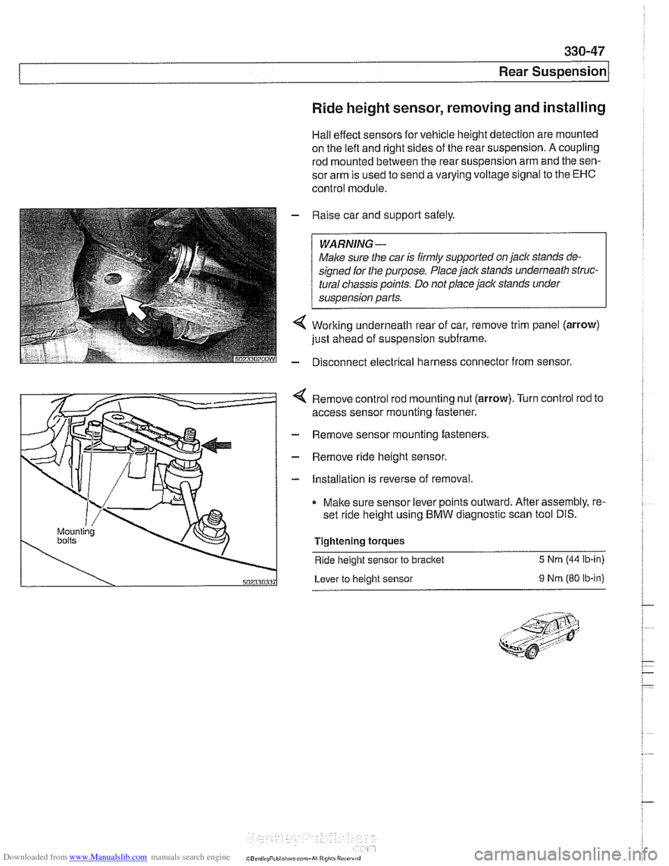
Working underneath rear of car, remove trim panel (arrow)
just ahead of suspension subframe.
Disconnect electrical harness connector from sensor.
4 Remove control rod mounting nut (arrow).Turn control rod to
access sensor mounting fastener.
- Remove sensor mounting fasteners.
- Remove ride height sensor.
- Installation is reverse of removal.
Make sure sensor lever points outward. After assembly, re-
set ride height using BMW diagnostic scan tool DIS.
Tightening torques
Ride
height sensor to bracket 5 Nrn (44 lb-in)
Lever to height sensor
9 Nrn (80 ib-in)
Page 768 of 1002
Downloaded from www.Manualslib.com manuals search engine
340-6
1 Brakes
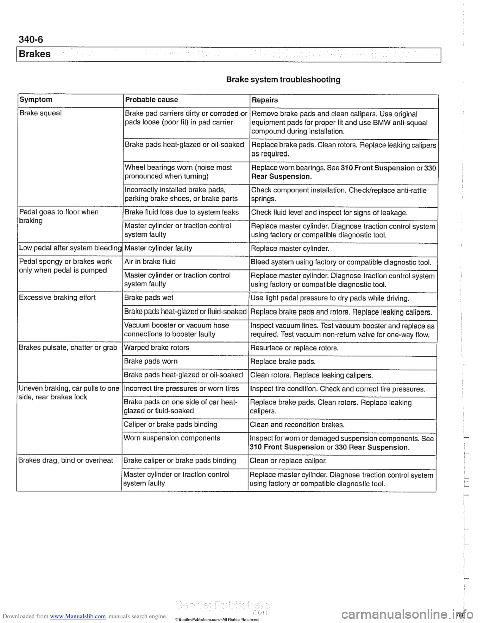
Brake system troubleshooting
/symptom I Probable cause 1 Repairs
Brake squeal
Pedal goes to floor when
bralting
Low pedal after system bleeding
Pedal spongy or brakes work
only when pedal is pumped
Excessive braking effort
Brakes pulsate, chatter or grab
Uneven
bralting, car pulls to one
side, rear braltes
loclt
Brakes drag, bind or overheat Brake
pad carriers dirty or corroded or
pads loose (poor fit) in pad carrier
Braite pads heat-glazed or oil-soaked
Wheel bearings worn (noise most
pronounced when turning)
Incorrectly Installed brake pads,
parking bralte shoes, or bralte parts
Brake fluid loss due to system leaks
Master cylinder or traction control
system faulty
Master cylinder faulty
Air in braite fluid
Master cylinder or traction control
system faulty
Brake pads wet
Brake pads
heat-glazedorfluid-soalted
Vacuum booster or vacuum hose
connections to booster faulty
--- Warped brake rotors
Brake pads worn
Brake pads heat-glazed or oil-soaked Remove
brake pads and clean calipers. Use original
equipment pads for proper fit and use BMW anti-squeal
compound during installation,
Replace brake pads. Ciean rotors. Replace leaking caliper:
as required.
Replace worn bearings. See 310 Front Suspension
or33C
Rear Suspension.
Check component installation. Checldreplace anti-rattle
springs.
Checlt fluid level and inspect for signs of leakage.
Replace master cylinder. Diagnose traction control system
using factory or compatible diagnostic tool.
Replace master cylinder.
Bleed system using factory or compatible diagnostic tool.
Replace master cylinder. Diagnose traction control system
using factory or compatible diagnostic tool.
Use light pedal pressure to dry pads while driving.
Replace
bralte pads and rotors. Replace leaking calipers.
lnspect vacuum lines. Test vacuum booster and replace as
required. Test vacuum non-return valve for one-way flow.
Resurface or replace rotors.
Replace brake pads.
Clean rotors. Replace leaiting calipers.
Incorrect tire pressures or worn tires
Brake pads on one side of car heat-
glazed or fluid-soaked
Caliper or brake pads binding
Worn suspension components
Brake caliper or brake pads binding
Master cylinder or traction control
system faulty lnspect
tire condition. Checlt and correct tire pressures.
Replace brake pads. Clean rotors. Replace leaking
calipers.
Clean and recondition brakes.
Inspect for worn or damaged suspension components. See
310 Front Suspension or 330 Rear Suspension.
Ciean or replace caliper.
Replace master cylinder. Diagnose traction control system
using faclory or compatible diagnostic tool.
Page 777 of 1002
Downloaded from www.Manualslib.com manuals search engine
340-1 5
Brakes
- Remainder of installation is reverse of removal.
- Clean brake caliper mounting bolts (7 mm Allen). Replace
ones which are not in perfect condition. Do not grease.
Top up brake fluid to MAX marking.
- Before driving car, pump bralte pedal several times so that
brake pads contact brake rotors.
Check that brake fluid level is correct. Top up if necessary.
Hold ignition key for at least
30 seconds in accessory po-
sition without starting engine. This clears any fault codes in
memory and turns off brake pad warning light.
Tightening torques Brake caliper to pad carrier
(7 mm Allen)
Front caliper
30 Nm (22 It-lb)
- Rear caliper 28 Nm (21 It-lb)
Road wheel to hub
120i 10 Nm (89i7 ft-lb)
Brake rotors, removing and installing
- Raise car and remove wheels
WARNING-
Male sure that the car is firmly supported on jack stands de-
signed for the purpose. Place jack stands beneath structural
chassis points. Do not place jack stands under suspension
parts.
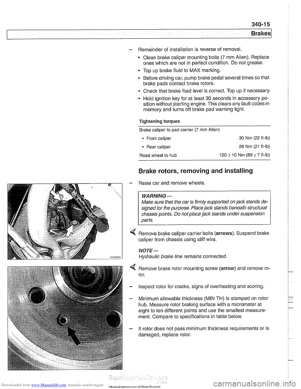
Remove brake caliper carrier bolts (arrows). Suspend brake
caliper from chassis using stiff wire.
NOTE-
Hydraulic brake line remains connected.
4 Remove bralte rotor mounting screw (arrow) and remove ro-
tor.
- Inspect rotor for cracks, signs of overheating and scoring.
- Minimum allowable thickness (MIN TH) is stamped on rotor
hub. Measure rotor braking surface with a micrometer at
eight to ten different points and use the smallest measure-
ment. Compare to specifications in table below.
- If rotor does not pass minimum thickness requirements or is
damaged, replace rotor.
Page 784 of 1002
Downloaded from www.Manualslib.com manuals search engine
Brakes
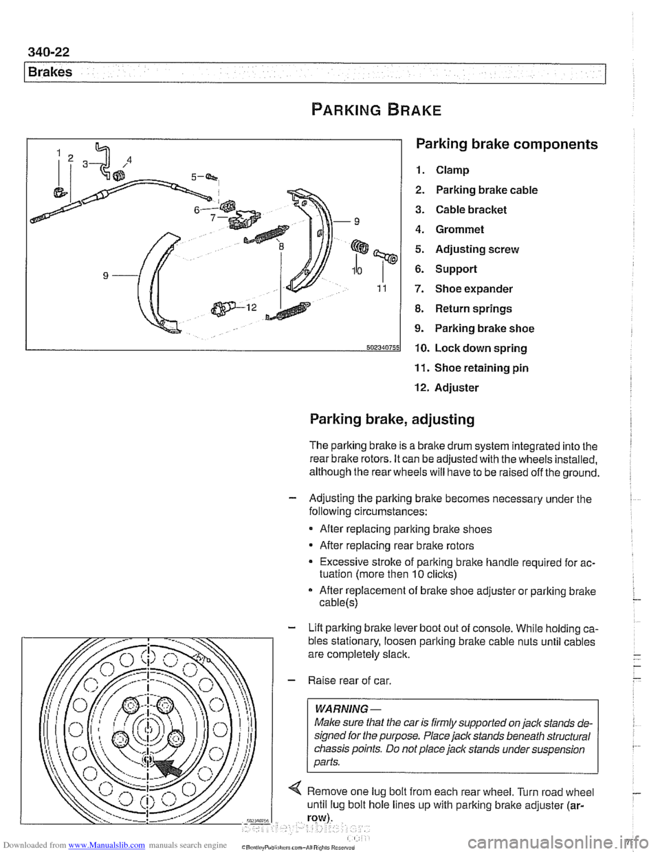
Parking brake components
1. Clamp
2. Parking brake cable
3. Cable bracket
4. Grommet
5. Adjusting screw
6. Support
7. Shoe expander
8. Return springs
9. Parking brake shoe
10. Lock down spring
11. Shoe retaining pin
12. Adjuster
Parking brake, adjusting
The parking brake is a brake drum system integrated into the I
rear brake rotors. It can be adjusted with the wheels installed,
although the rear wheels will have to be raised off the ground.
- Adjusting the parking bralte becomes necessary under the
following circumstances:
After replacing parking bralte shoes
After replacing rear brake rotors
Excessive stroke of parking brake handle required for ac-
tuation (more then
10 clicks)
After replacement of brake shoe adjuster or parking bralte
cable(s)
- Lift parking brake lever boot out of console. While holding ca-
Page 785 of 1002
Downloaded from www.Manualslib.com manuals search engine
340-23
Brakes
- Using flat-bladed screwdriver, reach into brake drum through
lug bolt hole. Turn brake adjuster until wheel no longer turns.
Back adjuster off
12 notches.
Parking brake adjusting (initial)
Back
off adjuster through wheel
lug bolt hole 12 notches
- Working inside car, set parking brake several times to seat
cable. Then pull parking brake
lever up two notches. Tighten
cable adjusting nuts until it is just possible to turn rear wheels
with slight resistance.
- Release lever and make sure rear wheels turn freely
- Turn on ignition. Pull up parlting brake lever 1 notch and
make sure that parking bralte warning light comes on. if not,
adjust parking bralte warning light contact switch.
- Install parking brake lever boot. Install road wheel lug bolts.
Tightening torque Road
wheel to hub 120 i. 10 Nrn (89 i- 7 ft-lb)
Parking brake shoes, removing and
installing
- Raise rear of car and remove road wheels.
WARNING-
Make sure that the car is firmly supported on jack stands de-
signed for
the purpose. Place jack stands beneath structural
chassis points. Do not place
jaclc stands under suspension
parts.
- Without disconnecting brake fluid hose, remove rear bralte
calipers from trailing arms. Remove rear brake rotors as de-
scribed earlier.
CAUTION-
Do not let the brake caliper assembly hang from the brake
hose. Support caliper from chassis with strong wire.
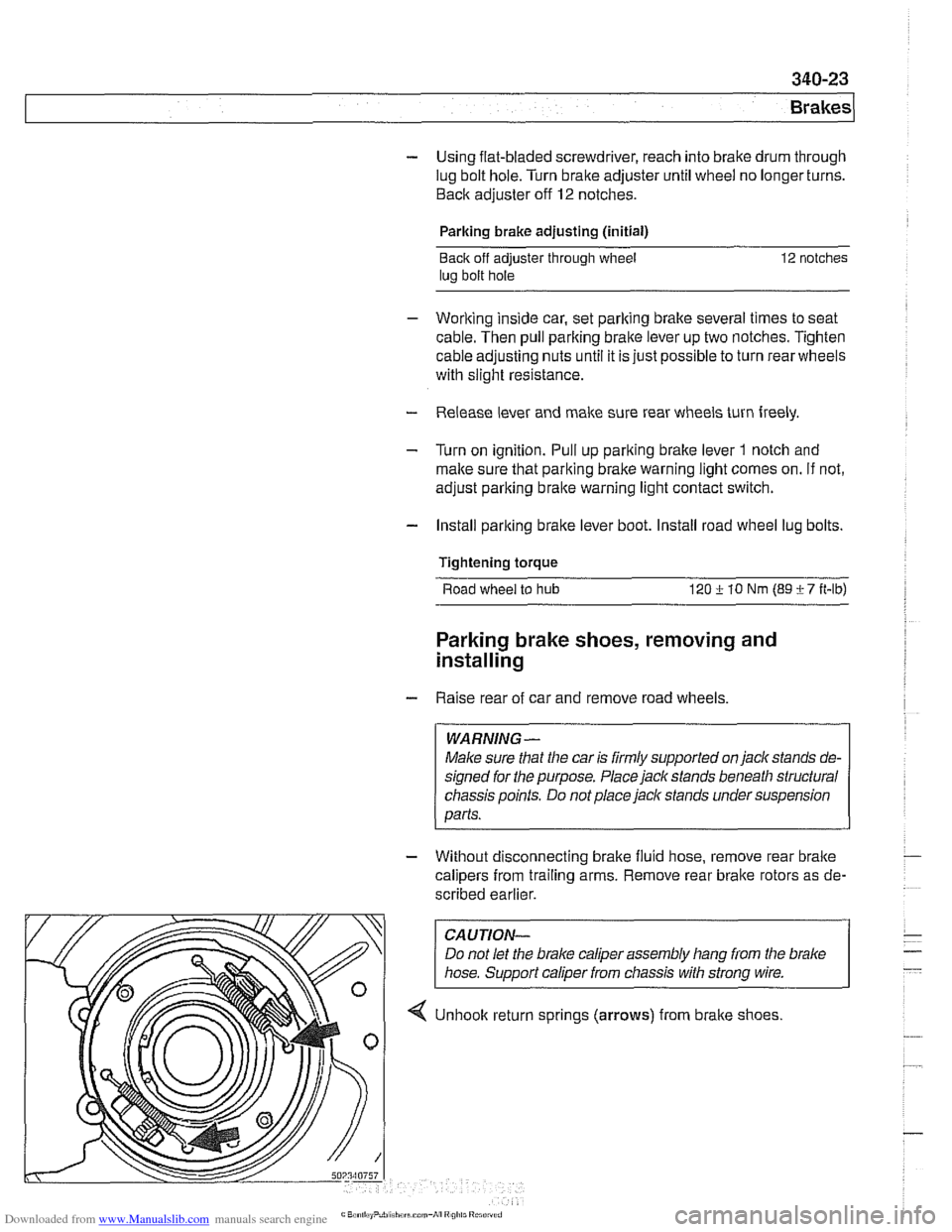
4 Unhook return sprlngs (arrows) from brake shoes
Page 786 of 1002
Downloaded from www.Manualslib.com manuals search engine
340-24
Brakes
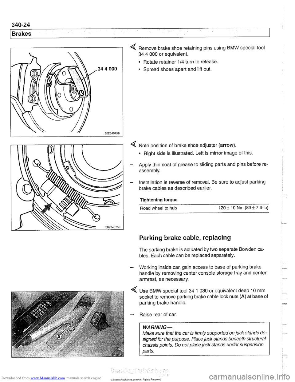
4 Remove brake shoe retaining pins using BMW special tool
34 4 000 or equivalent.
Rotate retainer
114 turn to release.
Spread shoes apart and lift out.
4 Note position of bralte shoe adjuster (arrow).
Right side is illustrated. Left is mirror image of this.
- Apply thin coat of grease to sliding parts and pins before re-
assembly.
- Installation is reverse of removal. Be sure to adjust parlting
bralte cables as described earlier.
Tightening torque
Road wheel to
hub 120 i lo Nm (89 i 7 ft-lb)
Parking brake cable, replacing
The parking brake is actuated by two separate Bowden ca-
bles. Each cable can be replaced separately.
- Working inside car, gain access to base of parking brake -
handle by removing center console storage tray and center
armrest, as necessary.
4 Use BMW special tool 34 1 030 or equivalent deep 10 mm
socket to remove parlting brake cable
loclc nuts (A) at base of
parking brake handle.
- Raise rear of car.
WARNING -
Male sure that the car is firmly supported on jack stands de-
signed for the purpose. Place jack stands beneath structural
chassis points. Do not place jaclc stands under suspension
Darfs.
Page 792 of 1002
Downloaded from www.Manualslib.com manuals search engine
1 Brakes
- Remove precharge pump mounting bracket fasteners and re-
move pump.
- Installation is reverse of removal, noting the following:
Be sure to replace rubber pump mounts if damaged
01
worn.
Bleed brakes as described earlier.
Tightening torque Brake line
to precharge pump 18 Nrn (13 ft-lb)
DSC pressure sensor (1 999 - 2002 models)
On 1999 and later DSC systems, the DSC pressure sensor is
screwed into the DSC hydraulic unit (right rear of engine com-
partment).
WARNING-
* €39 cars require special BMW service equipment to prop-
erly bleed the brakes. Removal of the
DSCpressure sensor
is not recommended unless this equipment is available. For
safety reasons, the brake system on cars with ABS must be
bled using the procedures described in this repair group.
Switch off ignition and remove
key to male sure brake
system cannot be activated.
- Disconnect electrical harness connector at switch.
- Use BMW special tool 34 5 160 to remove and install sensor.
Inspect threads and sealing surfaces for damage.
* Work quicltly to avoid excessive brake fluid leakage.
Tightening torque
Pressure sensor
to hydraulic 19 Nrn (14ft-lb)
unit
- Reconnect harness connector
- Bleed front brakes as described earlier.
- Press on brakes and check for leaks at sensor.
- Turn on ignition and firmly depress brake pedal. Check that
DSC warning light does not come on.
Page 799 of 1002
Downloaded from www.Manualslib.com manuals search engine
400-5
Body-General
Tailgate
The E39 Sporl Wagon tailgate is large with a low sill for easy
cargo loading. The tailgate opens to an angle of
88" mea-
sured from the rear roof pillar (D-pillar) and to a height of
2029
mm (79.8 in) measured from the ground to the upper edge of
the raised tailgate.
The rear window is bonded to a load bearing frame and can
be opened separately from the main tailgate. Tailgatesupport
gas springs are recessed into cavities in the roof.
Tailgate lock system
A mechanical tailgate lock cylinder is not used; the tailgate is
opened by the unlock pad above the license plate, the remote
tailgate switch located in the drivers kick panel, or via
FZV
(Iteyless entry) control.
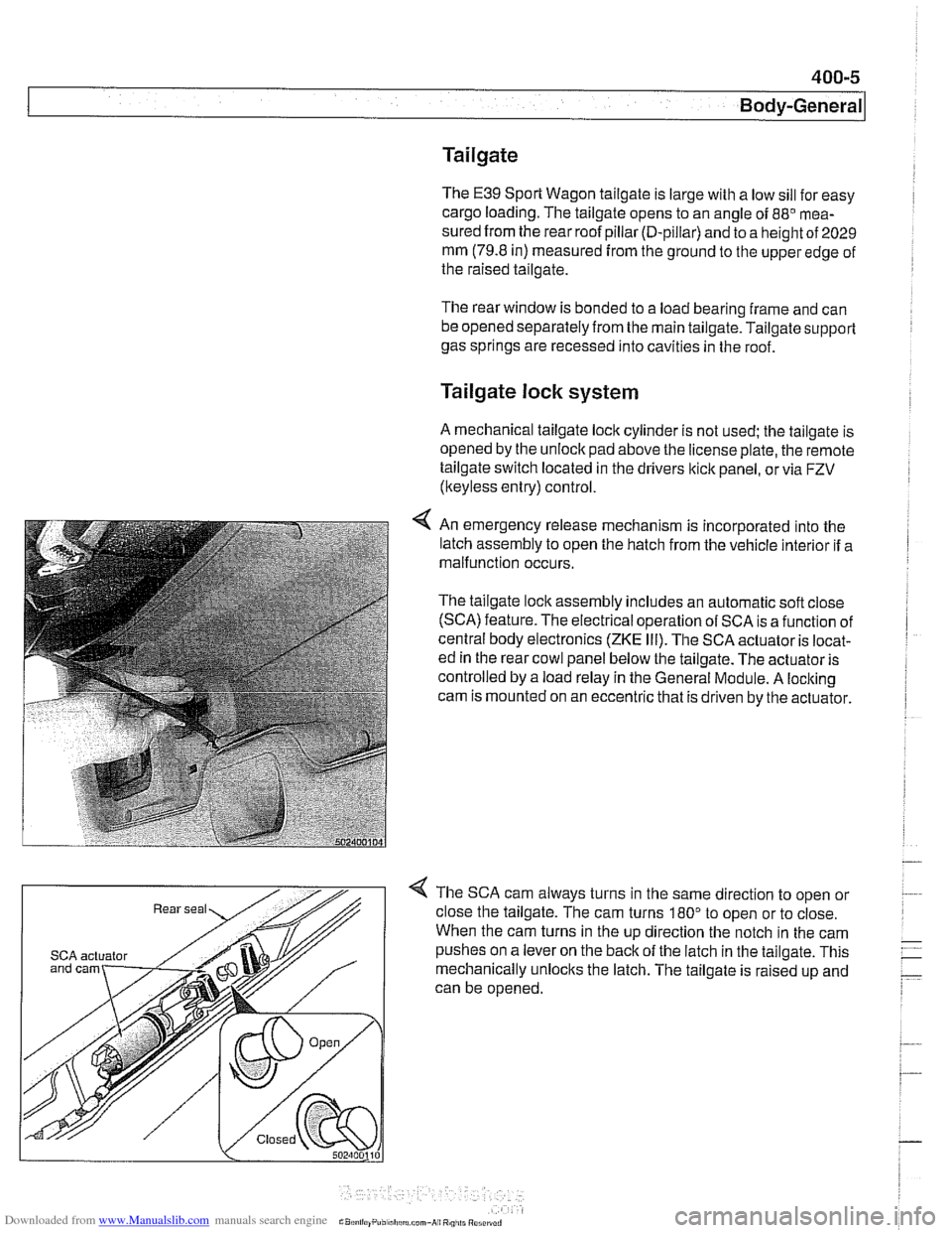
4 An emergency release mechanism is incorporated into the
latch assembly to open the hatch from the vehicle interior if a
malfunction occurs.
The tailgate lock assembly includes an automatic soft close
(SCA) feature. The electrical operation of SCA is a function of
central body electronics
(ZKE Ill). The SCA actuator is locat-
ed in the rear cowl panel below the tailgate. The actuator is
controlled by a load relay in the General Module. A locking
cam is mounted on an eccentric that is driven by the actuator.
4 The SCA cam always turns in the same direction to open or
close the tailgate. The cam turns
180" to open or to close.
When the cam turns in the up direction the notch in the cam
SCA actuator pushes on a lever on the back of the latch in the tailgate. This
mechanically unlocks the latch. The tailgate is raised up and
can be opened.
Page 802 of 1002
Downloaded from www.Manualslib.com manuals search engine
400-8
Body-General
Airbags
Front airbags, s~de a~rbags, pyrotechnic seat belt tensioners
and the Battery Safety Terminal (BST) are integrated into the
Supplemental Restraint System (SRS) and its variants.
NOTE-
The BMW SRS system is called Multiple Restra~nt System
(MRS). Over the years,
E39 cars were equipped with MRS,
MRS
11, MRS 111. Each version offers varied features and im-
provements over the previous system.
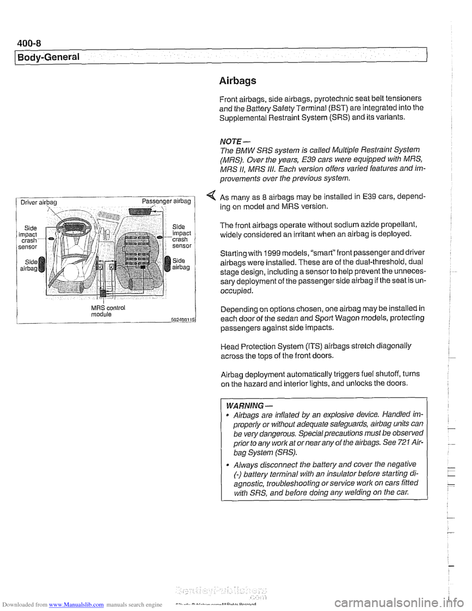
< As many as 8 airbags may be installed in E39 cars, depend-
ing on model and MRS version.
The front
airbags operate without sodium azide propellant,
widely considered an irritant when an
airbag is deployed.
Starting with
1999 models. "smart"front passenger and driver
airbags were installed. These are of the dual-threshold, dual
stage design, including a
sensorto help prevent the unneces-
sary deployment of the passenger side
airbag if the seat is un-
occupied.
MRS control Depend~ng on options chosen, one airbag may be installed in module each door of the sedan and Sport Wagon models, protecting
passengers against
s~de impacts.
Head Protection System (ITS)
airbags strelch diagonally
across the tops of the front doors.
Airbag deployment automatically triggers fuel shutoff, turns
on the hazard and interior lights, and unlocks the doors.
- -
WARNING -
Airbags are inflated by an explosive device. Handled im-
properly or without adequate safeguards,
airbag units can
be very dangerous. Special precautions must be observed
prior to any worlc at or near any of the airbags. See
721 Air-
bag System (SRS).
Always disconnect the battery and cover the negative
(-) battery terminal with an insulator before starting di-
agnostic, troubleshooting or service work on cars fitted
with SRS, and before doing any welding on the
car.