Cylinder BMW 540i 1999 E39 Workshop Manual
[x] Cancel search | Manufacturer: BMW, Model Year: 1999, Model line: 540i, Model: BMW 540i 1999 E39Pages: 1002
Page 322 of 1002
Downloaded from www.Manualslib.com manuals search engine
11 9-2
Lubrication System
This repair group covers lubrication system troubleshooting
as well as oil pan removal and oil pump replacement.
In 6-cylinder models, removal of the oil pan requires the re-
moval of the exhaust system and some front suspension
components. Those procedures are fully covered in:
180 Exhaust System
210 Clutch
230 Manual Transmission
0 240 Automatic Transmission
310 Front Suspension
320 Steering and Wheel Alignment
NOTE-
Oil change procedure and oil filter replacement are covered
in
020 Maintenance.
CAUTIOG
V8 engines: The oil pump fasteners (including the sprocket
retaining nut) are known to vibrate loose. This can result in oil
starvation and engine failure. Be sure to check oil bolts and
nut tightness whenever the
oilpump is accessible. If any fas-
teners are found to be loose, remove them and reinstall with
Loctite
Band torque to specifications.
Special tools
The engine needs to be properly supported while the front
suspension
subframe is lowered to access the oil pan.
A standard oil pressure gauge may be used for measuring oil
pressure.
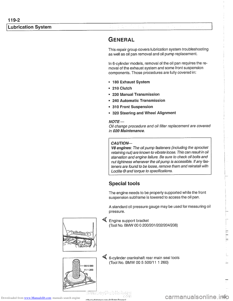
Engine support bracket
(Tool No, BMW 00 0 20012011202~2041208)
4 6-cylinder crankshalt rear main seal tools
(Tool No. BMW 00 5 50011
1 1 260)
Page 323 of 1002
Downloaded from www.Manualslib.com manuals search engine
1 19-3
Lubrication System
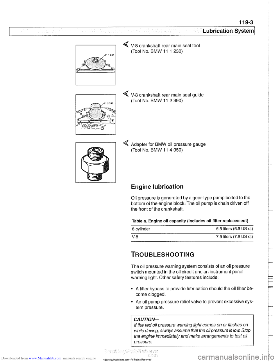
V-8 crankshaft rear main seal tool
(Tool No. BMW
11 1 230)
I i 4 V-8 crankshaft rear main seal ouide
4 Adapter for BMW oil pressure gauge
(Tool No. BMW
11 4 050)
Engine lubrication
Oil pressure is generated by a gear-type pump bolted to the
bottom oi the engine block. The oil pump is chain driven off
the front of the crankshaft.
Table a. Engine oil capacity (includes oil filter replacement)
6-cylinder 6.5
liters (6.9
US qt)
V-8 7.5 liters (7.9 US qt)
The oil pressure warning system consists of an oil pressure
switch mounted in the oil circuit and an instrument
panel
warning light. Other saiety features include:
Q A filter bypass to provide lubrication should the oil filter be-
come clogged.
An oil pump pressure relief valve to prevent excessive sys-
tem pressure.
CAUTIOI\C
If the red oil pressure warning light comes on or flashes on
while driving, always assume that the oilpressure is low. Stop
the engine immediately and make arrangements to test oil
pressure.
Page 324 of 1002
Downloaded from www.Manualslib.com manuals search engine
-
I Lubrication System - I
Oil pressure, checking
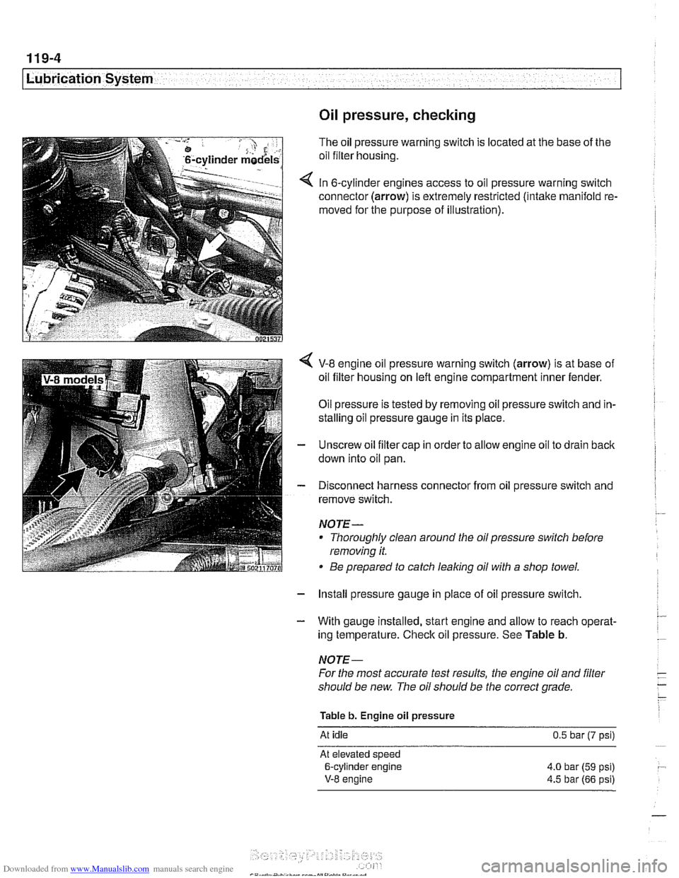
The oil pressure warning switch is located at the base of the
oil filter housing.
In 6-cylinder engines access to oil pressure warning switch
connector (arrow) is extremely restricted (intake manifold re.
moved for the purpose of illustration).
V-8 engine oil pressure warning switch (arrow) is at base of
oil filter housing on left engine compartment inner fender.
Oil pressure is tested by removing oil pressure switch and in-
stalling oil pressure gauge in its place.
Unscrew oil filter cap in order to allow engine oil to drain back
down into oil pan.
Disconnect harness connector from oil pressure switch and
remove switch.
NOJE-
Thoroughly clean around the oil pressure switch before
removing it.
Be prepared to catch leaking oil with a shop towel.
- Install pressure gauge in place of oil pressure switch,
- With gauge installed, start engine and allow to reach operat-
ing temperature. Check oil pressure. See Table b.
NOJE-
For the most accurate test results, the engine oil and filter
should be new. The oil should be the correct grade.
Table b. Engine oil pressure
At idle 0.5 bar (7 psi)
At elevated speed
6-cylinder engine 4.0 bar
(59 psi)
V-8 engine 4.5 bar (66 psi)
Page 326 of 1002
Downloaded from www.Manualslib.com manuals search engine
Lubrication System
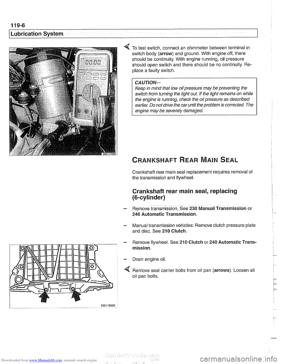
To test switch, connect an ohmmeter between terminal in
switch body (arrow) and ground. With engine off, there
should be continuity. With engine running, oil pressure
should open switch and there should be no continuity. Re-
place a faulty switch.
CAUTION-
Keep in mind that low oil pressure may be preventing the
switch from turning the light out
If the light remains on while
the engine is running, check the oil pressure as described
earlier. Do not drive the car until the problem is corrected. The
engine may be severely damaged.
Crankshaft rear main seal replacement requires removal of
the transmission and flywheel.
Crankshaft rear main seal, replacing
(&cylinder)
- Remove transmission. See 230 Manual Transmission or
240 Automatic Transmission.
- Manual transmission vehicles: Remove clutch pressure plate
and disc. See
210 Clutch.
- Remove flywheel. See 210 Clutch or 240 Automatic Trans-
mission.
- Drain engine oil.
4 Remove seal carrier bolts from oil pan (arrows). Loosen all
oil pan bolts.
Page 330 of 1002
Downloaded from www.Manualslib.com manuals search engine
11 9-1 0
Lubrication System
Oil pan, removing and installing
(6-cylinder)
The engine oil pan removal procedure requires that the en-
gine be supported from the top and the front suspension
sub-
frame be lowered.
- Raise car and place securely on jack stands.
Make sure the car is stable and well supported at all times.
Use a professional automotive
lift orjackstands designed for
- Remove splash shield from under engine.
- Drain engine oil as described in 020 Maintenance.
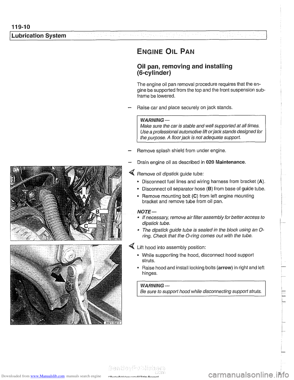
4 Remove oil dipsticlc guide tube:
Disconnect fuel lines and wiring harness from
bracket (A).
- Disconnect oil separator hose (B) from base of guide tube.
Remove mounting bolt
(C) from left engine mounting
bracket and remove tube from oil pan.
NOTE-
* If necessary, remove air filter assembly for better access to
dipsticlc tube.
The dipstick guide tube is sealed in the block using an
O-
ring. Check that the O-ring comes out with the tube.
4 Lift hood into assembly position:
While supporting the hood, disconnect hood support
struts.
Raise hood and install
loclting bolts (arrow) in right and left
hinges.
WARNING-
Be sure to support hood while disconnecting support struts.
Page 332 of 1002
Downloaded from www.Manualslib.com manuals search engine
119-12
Lubrication System 1
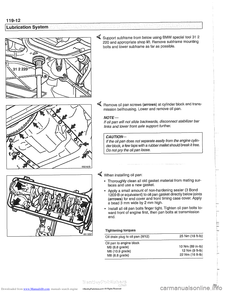
4 Support subframe from below using BMW special tool 31 2
220 and appropriate shop lift. Remove
subframe mounting
bolts and lower
subframe as far as possible.
Remove oil pan screws (arrows) at cylinder block and trans-
mission bellhousing. Lower and remove oil pan.
NOTE-
If oil pan will not slide backwards, disconnect stabilizer bar
links and lower front axle support further.
If the oil pan does not separate easily from the engine cylin-
der
block, a few taps with a rubber malletshould breakit free.
Do not
pry the oil pan loose.
When installing oil pan: Thoroughly clean all old gasket material from mating sur-
faces and use a new gasket.
Apply a small amount of non-hardening sealer
(3 Bond
12098 or equivalent) to oil pan gasket directly below joints
(arrows) for end cover and front timing case cover. Apply
a bead
3 mm wide by 2 mm high.
Install all oil pan bolts finger tight. Tighten oil pan bolts to-
ward front of engine first, then pan bolts at transmission
end.
Tightening
torques
Oil drain plug to oil pan (M12) 25 Nm (18 ft-lb)
Oil pan to engine block
MG (8.8 grade)
MG (10.9 grade)
M8 (8.8 grade)
10 Nm (89 In-lb)
12 Nm (9 ft-lb)
22 Nrn (16 R-lb)
Page 336 of 1002
Downloaded from www.Manualslib.com manuals search engine
-
Lubrication System - - -- . - I
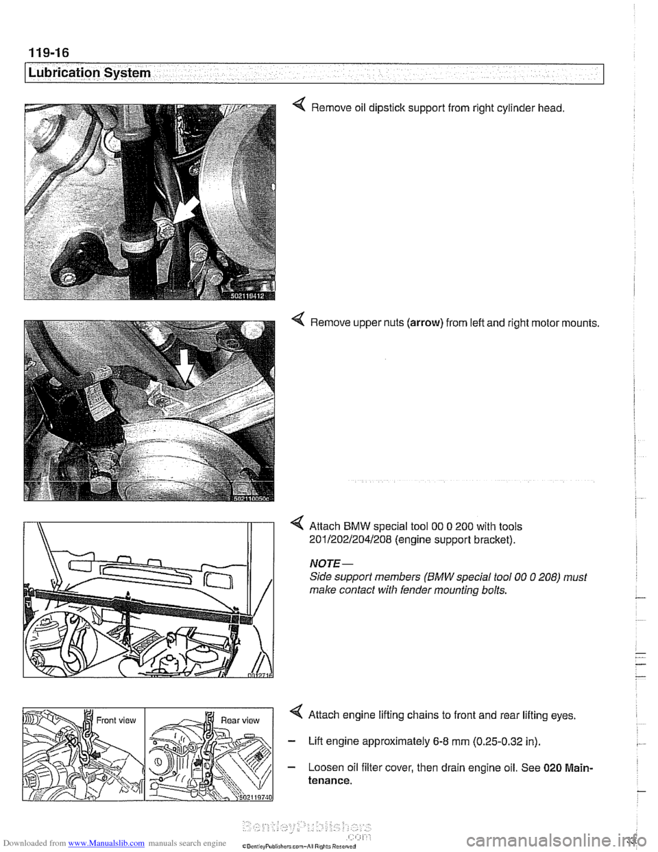
< Remove oil dipstick support from right cylinder head.
4 Remove upper nuts (arrow) from left and right motor mounts.
4 Attach BMW special tool 00 0 200 with tools
i\ 201/202R04/208 (engine suppon bracket).
Page 340 of 1002
Downloaded from www.Manualslib.com manuals search engine
Lubr~cat~on System r- -
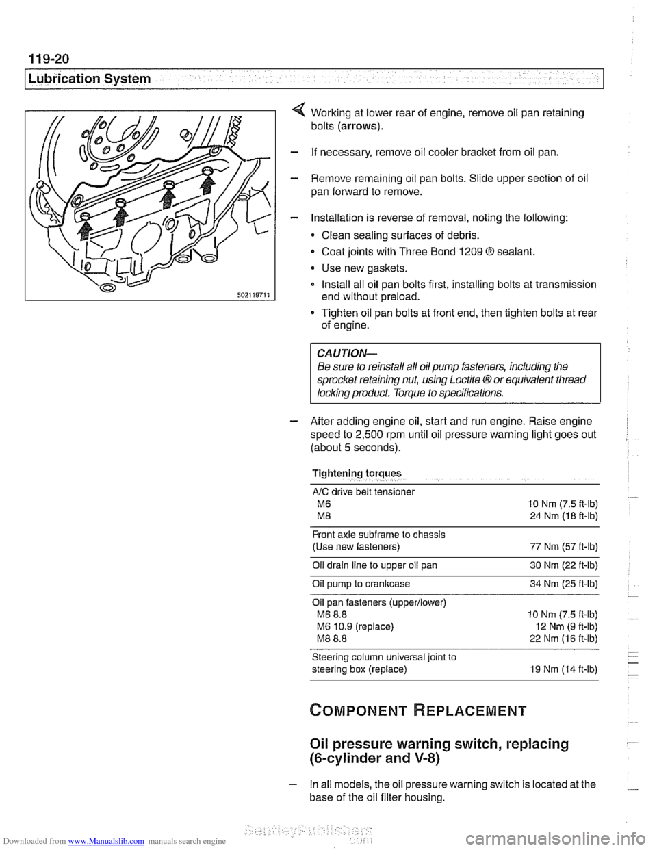
Working at lower rear of engine, remove oil pan retaining
bolts
(arrows).
- If necessary, remove oil cooler bracket from oil pan.
- Remove remaining oil pan bolts. Slide upper section of oil
pan forward to remove.
- Installation is reverse of removal, noting the following:
Clean sealing surfaces of debris.
- Coat joints with Three Bond 1209 O sealant.
Use new gaskets.
Install all oil pan bolts first, installing bolts at transmission
end without preload.
Tighten oil pan bolts at front end, then tighten bolts at rear
of engine.
Be sure to reinstall all oil
pump fasteners, including the
sprocl
speed to
2,500 rpm until oil pressure warning light goes out
(about
5 seconds).
Tightening torques
AIC drive belt tensloner
M6 10 Nm (7.5 it-lb)
M8 24 Nm (18 ft-lb)
Front axle
subframe to chassis
(Use new fasteners) 77 Nm (57 ft-lb)
Oil drain
line to upper oil pan 30 Nm (22 ft-lb)
Oil pump to crankcase 34 Nm (25 ft-lb)
Oil pan fasteners
(upperllower)
M6 8.8 10 Nm (7.5 ft-lb)
M6 10.9 (replace)
I2 Nm (9 ft-lb)
M8 8.8 22 Nm (16 ft-lb)
Steering column universal joint to
steering box (replace) 19 Nm (14 ft-lb)
Oil pressure warning switch, replacing
(&cylinder and V-8)
- In all models, the oil pressure warning switch is located at the
base of the oil filter housing.
Page 341 of 1002
Downloaded from www.Manualslib.com manuals search engine
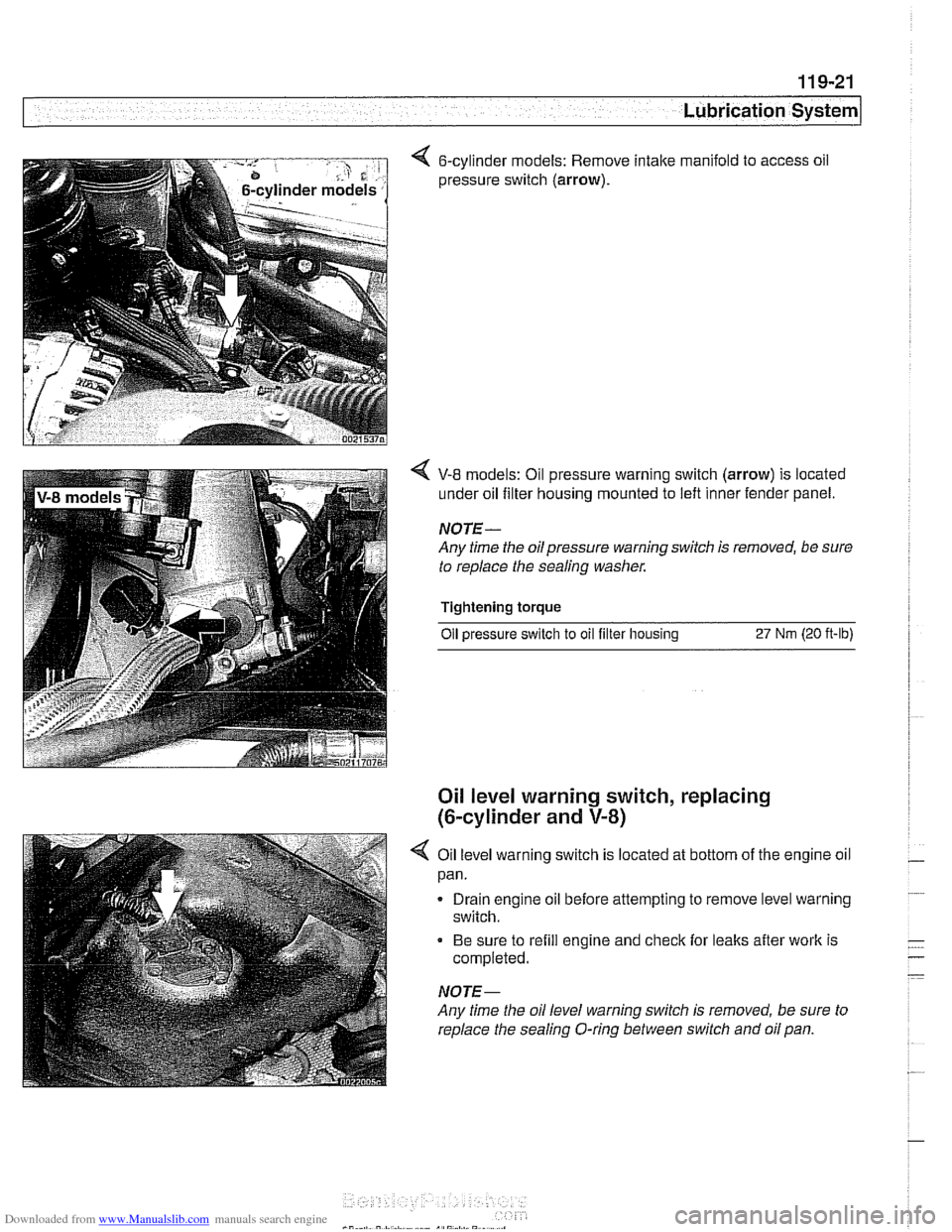
< 6-cylinder models: Remove intake manifold to access oil
pressure switch
(arrow).
V-8 models: Oil pressure warning switch (arrow) is located
under oil filter housing mounted to left inner fender panel.
NOTE-
Any time the oilpressure warning switch is removed, be sure
to replace the sealing washer.
Tightening torque Oil
~ressure switch to oil filter housins 27 Nrn (20 ft-lb)
Oil level warning switch, replacing
(6-cylinder and
V-8)
4 Oil level warning switch is located at bottom of the engine oil
pan.
Drain engine oil before attempting to remove level warning
switch.
Be sure to refill engine and check for leaks after work is
completed.
NOTE-
Any time the oil level warning switch is removed, be sure to
replace the sealing O-ring between switch and oil pan.
Page 342 of 1002
Downloaded from www.Manualslib.com manuals search engine
/Lubrication System
Oil pump, removing and installing
(&cylinder)
Oil pump assembly
(6-cylinder from 9/98)
CAUTIOI\C
Oil pump sproclcet nut has left-hand threads. Turn clockwise
to loosen.
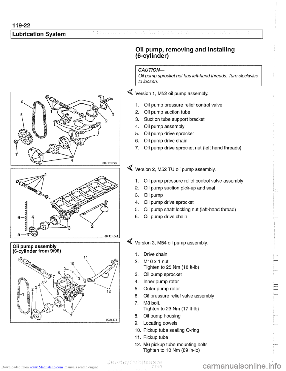
4 Version 1, M52 oil pump assembly.
1. Oil pump pressure relief control valve
2. Oil pump suction tube
3. Suction tube support bracket
4. Oil pump assembly
5. Oil pump drive sprocltet
6. Oil pump drive chain
7. Oil pump drive sprocket nut (left hand threads)
4 Version 2, M52 TU oil pump assembly.
1. Oil pump pressure relief control valve assembly
2. Oil pump suction pick-up and seal
3. Oil pump
4. Oil pump drive sprocket
5. Oil pump shaft locking nut (left-hand thread)
6. Oil pump drive chain
Version
3, M54 oil pump assembly,
1. Drive chain
2.
MlO x 1 nut
Tighten to 25 Nm (18 ft-lb)
3. Oil pump sprocket
4. Inner pump rotor
5. Outer pump rotor
6. Oil pressure relief valve assembly
7. M8 bolt.
Tighten to 23 Nm
(17 it-lb)
8. Oil pump housing
9. Locating dowels
10. Pickup tube sealing O-ring
11. Pickup tube
12. M6 pickup tube mounting bolts
Tighten to
10 Nm (89 in-lb)