Cylinder BMW 540i 1999 E39 Workshop Manual
[x] Cancel search | Manufacturer: BMW, Model Year: 1999, Model line: 540i, Model: BMW 540i 1999 E39Pages: 1002
Page 346 of 1002
Downloaded from www.Manualslib.com manuals search engine
11 9-26
/Lubrication System
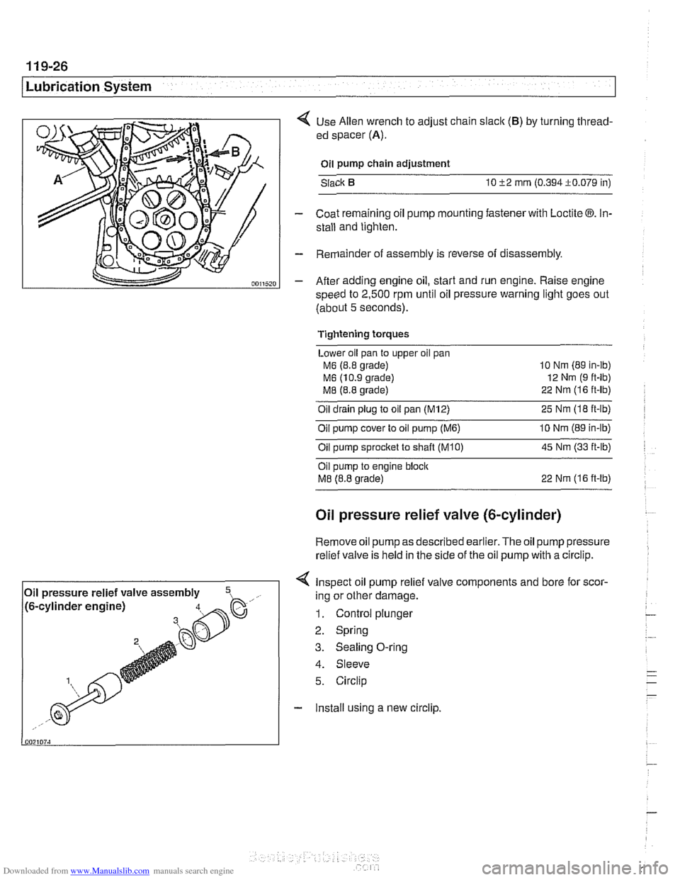
< Use Allen wrench to adjust chain slaclc (B) by turning thread-
ed spacer
(A).
Oil pump chain adjustment
Slack
10 52 mrn (0.394i0.079 in)
- Coat remaining oil pump mounting fastener with Loctite 03. In-
stall and tighten.
- Remainder of assembly is reverse of disassembly.
- After adding engine oil, start and run engine. Raise engine
speed to
2,500 rpm until oil pressure warning light goes out
(about
5 seconds).
Tightening torques
Lower oil pan to upper oil pan
M6 (8.8 grade) 10
Nm (89 in-ib)
M6 (10.9 grade) 12
Nm (9 ft-lb)
M8 (8.8 grade) 22
Nrn (1 6 ft-lb)
Oil drain plug to oil pan (M12) 25 Nm (I8 ft-lb)
Oil pump cover to oil pump
(M6) 10 Nrn (89 in-lb)
Oilpump sprocket to shaft TKO) 45 Nm (33 it-lb)
Oil pump to engine bloclc
M8 (8.8 grade) 22 Nrn (16 ft-lb)
Oil pressure relief valve (&cylinder)
Remove oil
pump as described earlier. The oil pump pressure
relief valve is held in the side of the
oil pump with a circlip.
< Inspect oil pump relief valve components and bore for scor-
4. Sleeve
5. Circlip
- Install using a new circlip.
Oil
pressure relief valve assembly
,- ..., !~. -.-~. - ~- -~!~~-% h. .- .,, /to-cy~~noer engrnej ing or other damage.
1. Control plunger
2. Spring
3. Sealing O-ring
Page 352 of 1002
Downloaded from www.Manualslib.com manuals search engine
I lgnition System
Additional information about DTCs and engine management
system electronic system diagnosis is provided in
OBD On-
Board Diagnostics.
Table a. Engine management systems
Year
l~ngine I Engine type IDME svstem I - I - . . I
Ignition system
1997-1 998
1997
1998
1999-2002
4 All engines use a distributorless ignition system with individ-
ual ignition coils for each cylinder. There is no distributor cap
or ignition rotor.
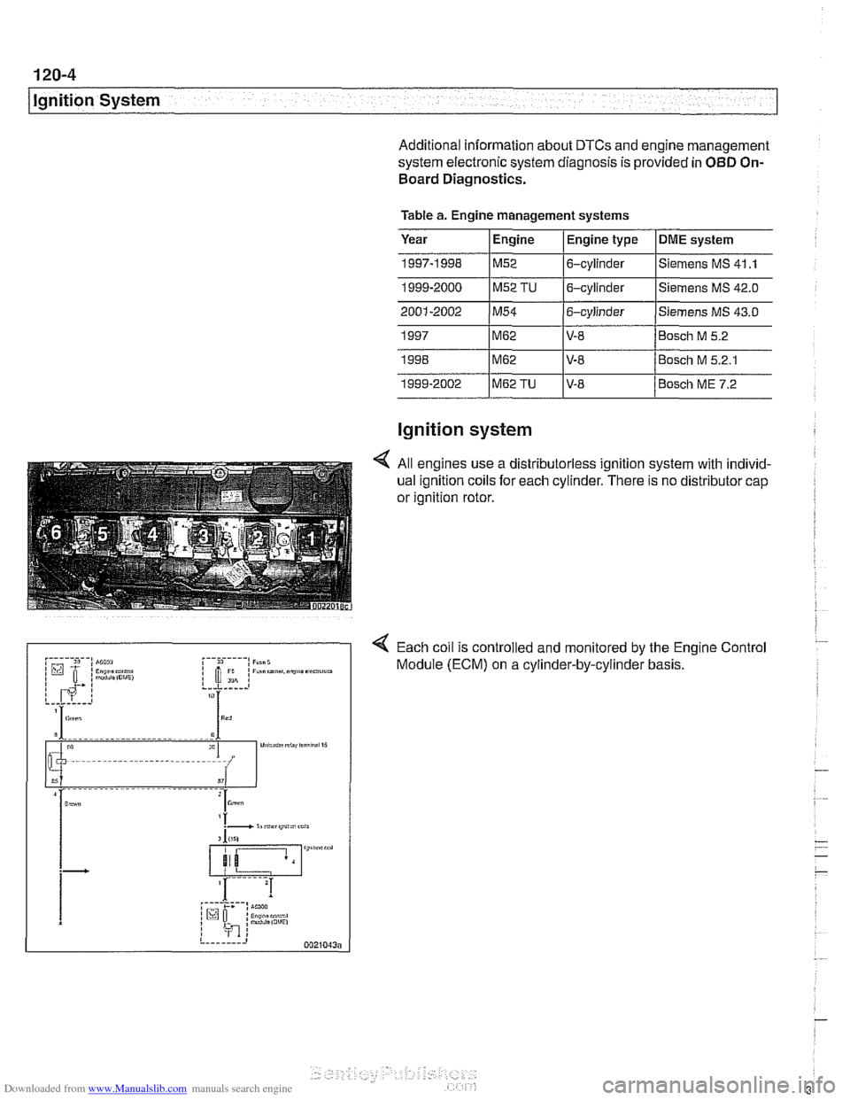
4 Each coil is controlled and monitored by the Engine Control
Module (ECM) on a cylinder-by-cylinder basis.
1999-2000
1~52 TU 16-cylinder l~iemens MS
42.0
M62
M62
M62TU
Siemens MS 41 .I M52 6-cylinder
V-8
V-8 V-8 Bosch
M 5.2
Bosch M 5.2.1
Bosch ME 7.2
Page 353 of 1002
Downloaded from www.Manualslib.com manuals search engine
Lnition switch
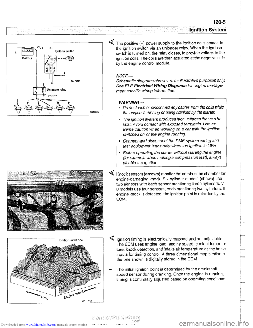
4 The positive (+) power supply to the ignition coils comes to
the ignition switch via an unloader relay. When the ignition
switch is turned on, the relay closes, to provide voltage to the
ignition coils. The coils are then actuated at the negative side
by the engine control module.
NOTE-
Schematic diagrams shown are for illustrative purposes only.
See ELE Electrical Wiring Diagrams for engine manage-
ment specific wiring information.
WARNING- Do not touch or disconnect any cables from the coils while
the engine is running or being cranked by the starter:
The ignition system produces high voltages that can be
fatal. Avoid contact with exposed terminals. Use ex-
treme caution when
working on a car with the ignition
switched on or the engine running.
* Connect and disconnect the DME system wiring and
test equipment leads only when the ignition is
OFF
Before operating the starter without starting the engine
(for example when
making a compression test), always
disable the ignition.
4 Knock sensors (arrows) monitor the combustion chamber for
engine-damaging knock. Six-cylinder models (shown) use
two sensors with each sensor monitoring three cylinders.
V-
8 models use four sensors, each monitoring two cylinders. If
engine
knock is detected, the ignition point is retarded by the
ECM.
I Ignition advance Ignition timing is electronically mapped and not adjustable.
The ECM uses engine load, engine speed, coolant tempera-
ture, knock detection, and intake air temperature as the basic
inputs for timing control.
A three dimensional map similar to
the one shown is digitally stored in the ECM.
- The initial ignition point is determined by the crankshaft
speed sensor during cranking. Once the engine is running.
timing is continually adjusted based on operating conditions.
Page 354 of 1002
Downloaded from www.Manualslib.com manuals search engine
120-6
lgnition System
lgnition system, troubleshooting
Troubleshooting ignition system faults should begin with an
interrogation of the On-Board Diagnostics (OBD
II) system.
The OBD
II system detects ignition system misfire and other
related faults. When faults are detected, the OBD
II system
stores a Diagnostic Trouble Code (DTC) in the Engine Con-
trol Module (ECM) along with other pertinent fault information.
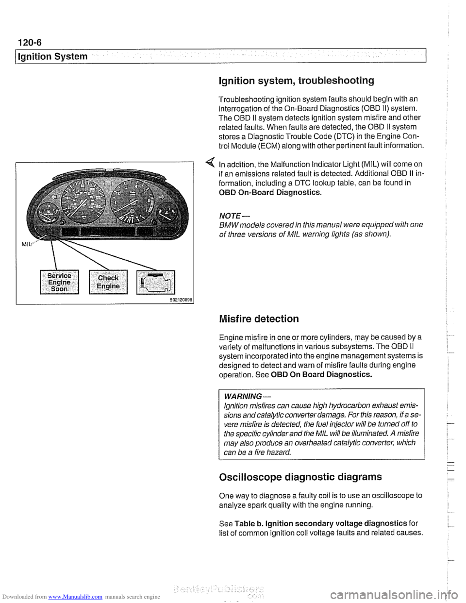
4 In addition, the Malfunction Indicator Light (MIL) will come on
if an emissions related fault is detected. Additional OBD
II in-
formation, including a DTC lookup table, can be found in
OED On-Board Diagnostics.
NOTE-
BMWmodels covered in this manual were equipped with one
of three versions of
MIL warning lights (as shown).
Misfire detection
Engine m~sfire in one or more cylinders, may be caused by a
var~ety of malfunctions in various subsystems. The OBD II
system ~ncorporated into the engine management systems is
des~gned to detect and warn of misfire faults during englne
operat~on. See OED On Board Diagnostics.
WARNING -
lgnition misfires can cause high hydrocarbon exhaust emis-
sions andcatalytic converter damage. For this reason, if a se-
vere misfire is detected, the fuel injector
will be turned off to
the specific cylinder and the
MIL will be illuminated. A misfire
may also produce an overheated catalytic converter, which
can be a fire hazard.
Oscilloscope diagnostic diagrams
One way to diagnose a faulty coil is to use an oscilloscope to
analyze spark quality with the engine running.
See Table b. lgnition secondary voltage diagnostics for
list of common ignition
coil voltage faults and related causes.
Page 357 of 1002
Downloaded from www.Manualslib.com manuals search engine
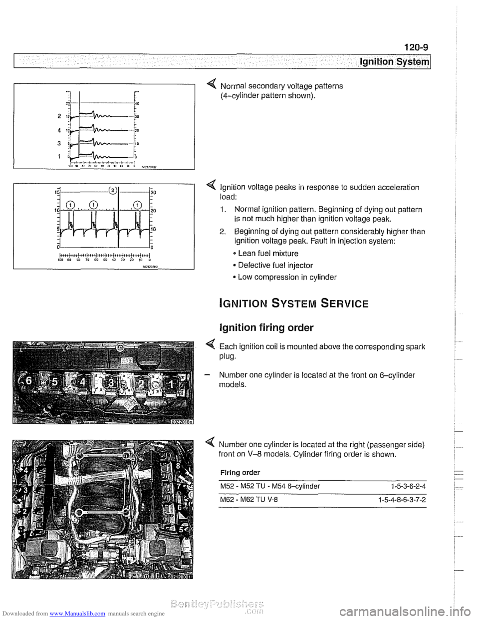
< Ignition voltage peaks in response to sudden acceleration
load:
1. Normal ignition pattern. Beginning of dying out pattern
is not much higher than ignition voltage peak.
2. Beginning of dying out pattern considerably higher than
ignition voltage peak. Fault in injection system:
Lean fuel mixture
Defective fuel injector
Low compression in cylinder
-, :I 1- i :
Ignition firing order
Normal secondary voltage patterns
(4-cylinder pattern shown).
4 Each ignition coil is mounted above the corresponding spark
plug.
- Number one cylinder is located at the front on 6-cylinder
models.
Number one cylinder is located at the right (passenger side)
front on
V-8 models. Cylinder firing order is shown.
Firing order
M52 - M52 TU - M54 6-cylinder 1-5-3-6-2-4
M62 - M62 TU V-8 1-5-4-8-6-3-7-2
Page 358 of 1002
Downloaded from www.Manualslib.com manuals search engine
.-
ignition System
Disabling ignition system
The ignition system operates in a lethal voltage range and
should be disabled any time engine service or repair work is
being done that requires the ignition to be switched on.
The engine management system can be disabled by remov-
ing the DME main relay. The relay is located in the electronics
box (E-box) in the left rear of the engine
compartment, be.
neath the interior microfilter housing.
CAUTION- Relay locations may
vary. Use care when identifying relays.
See
610 Electrical Component Locations.
Checking for spark
CAUTION-
If
a spark test is done incorrecth damage to the Engine Con-
trol Module
(ECM) or the ignition coils may result.
NOTE-
Spark plug replacement is covered in 020 Maintenance.
Check~ng for spark is d~fflcult on englnes wlth d~str~butorless
ignition systems.
Try removing the spark plugs and inspecting for differences between them.
A poor-firing plug may be wet with fuel and/or ~. - ~
black and sooty, but not always. If a coil is not operating, the
engine management system will electrically disable the fuel
injector to that cylinder. The key is to look for differences be-
tween cylinders.
Ignition coil assembly, testing and
replacing
C4 UTION-
Use a digital multimeter for the following tests. I
- Remove plastic engine cover from top of valve cover by pry-
ing off bolt covers and removing cover mounting bolts.
- Raise car slowly while constantly checking position of jack
and car.
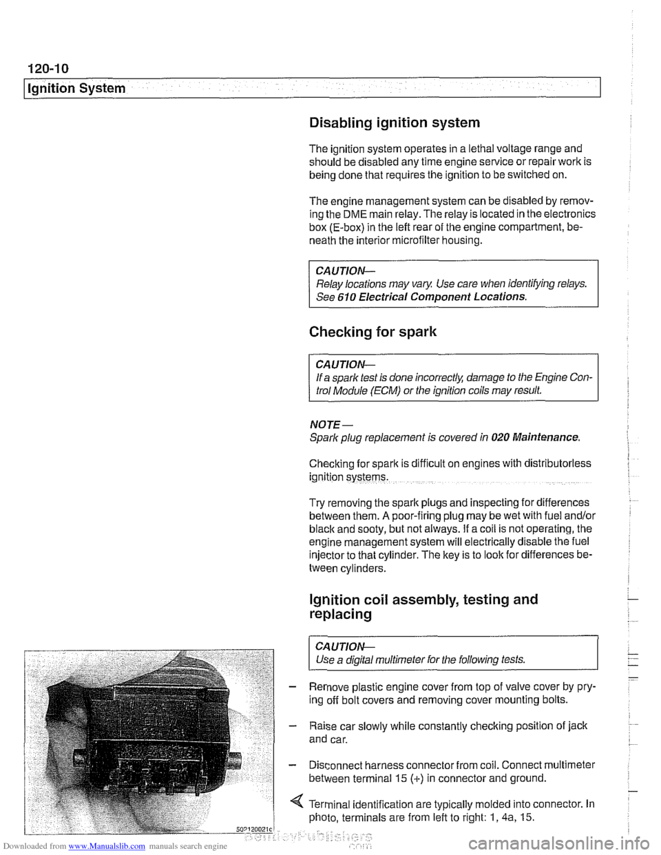
- Disconnect harness connector from coil. Connect multimeter
between terminal 15
(+) in connector and ground.
4 Terminal identification are typically molded into connector. In
photo, terminals are from left to right: 1,
4a, 15.
Page 360 of 1002
Downloaded from www.Manualslib.com manuals search engine
120-1 2
ignition System
Crankshaftspeedsensor
Crankshaft speed sensor, replacing (M52, M52 TU and
M54 engines)
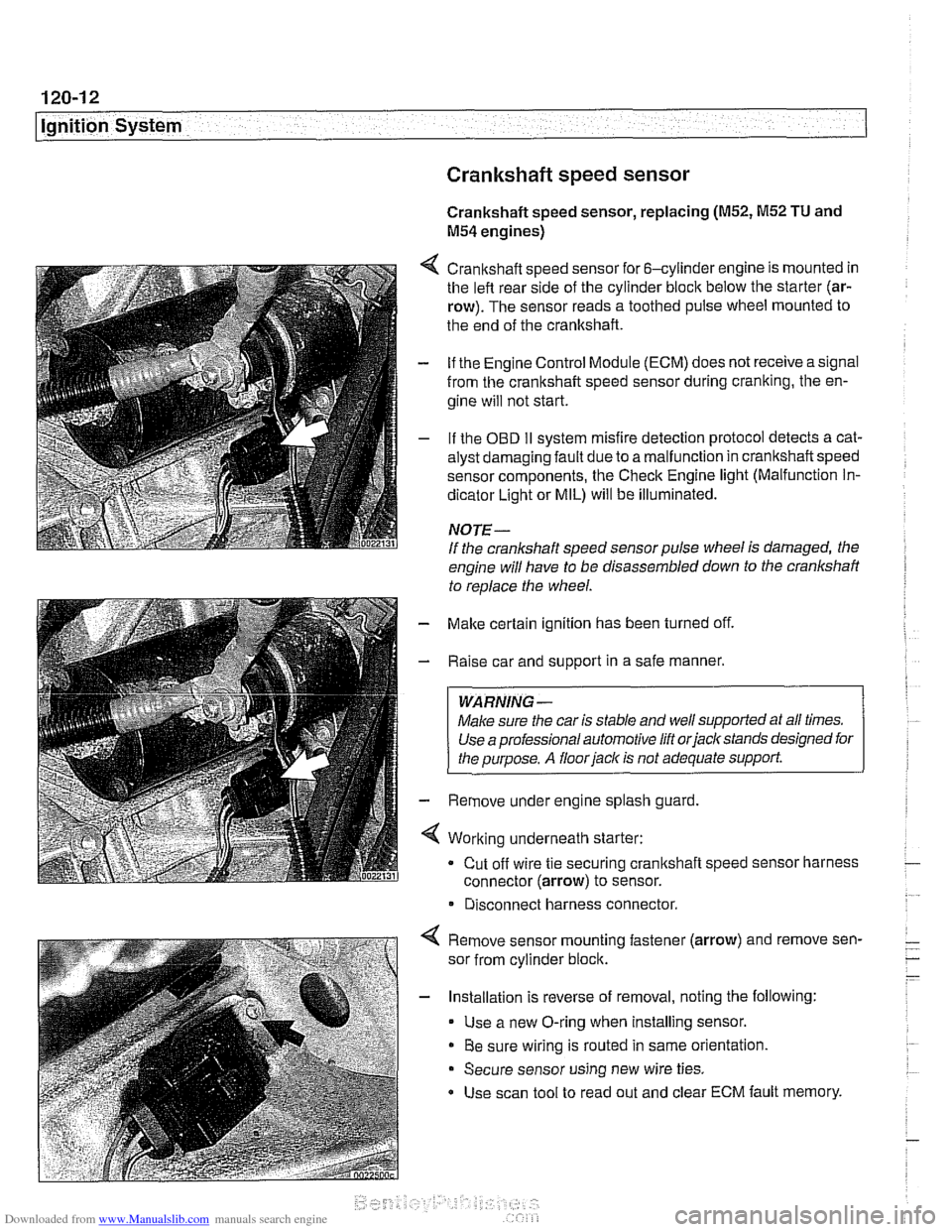
4 Crankshaft speed sensor for 6-cylinder engine is mounted in
the left rear side of the cylinder block below the starter (ar-
row). The sensor reads a toothed pulse wheel mounted to
the end of the crankshaft.
- if the Engine Control Module (ECM) does not receive a signal
from the crankshaft speed sensor during cranking, the en-
gine will not start.
- If the OBD II svstem misfire detection ~rotocol detects a cat- - - ~~
alysr oarnagin; faLlt oJe to a ma I-nclion in crandshafi speeo
sensor components. Ine Check Engine
lignr (Malfuncrion In-
dicator Light or MIL) will be illuminated.
NOTE-
If the crankshaft speed sensor pulse wheel is damaged, the
engine will have to be disassembled down to the crankshaft
to
reolace the wheel.
- Make certain ignition has been turned off.
- Raise car and support in a safe manner.
WARNING -
Make sure the car is stable and well supported at all times.
Use a professional automotive lift orjacltstands designed for
the ouroose.
A floor iaclc is not adequate support.
- Remove under engine splash guard
4 Working underneath starter:
Cut off wire tie securing crankshaft speed sensor harness
connector (arrow) to sensor.
* Disconnect harness connector.
4 Remove sensor mounting fastener (arrow) and remove sen-
sor from cylinder block.
- Installation is reverse of removal, noting the following:
Use a new O-ring when installing sensor.
Be sure wiring is routed in same orientation.
Secure sensor using new wire ties.
Use scan tool to read out and clear ECM fault memory.
Page 362 of 1002
Downloaded from www.Manualslib.com manuals search engine
I Ignition System
Camshaft position sensors
The camshaft position sensors are used by the englne man-
agement system for VANOS control, sequential fuel injection
and knock control.
Intake camshaft position sensor, replacing
(M52,M52 TU
and M54 engines)
- Make certain ignition has been turned off.
- Remove plastic cover from above fuel injectors by prying off
bolt covers and removing cover mounting bolts.
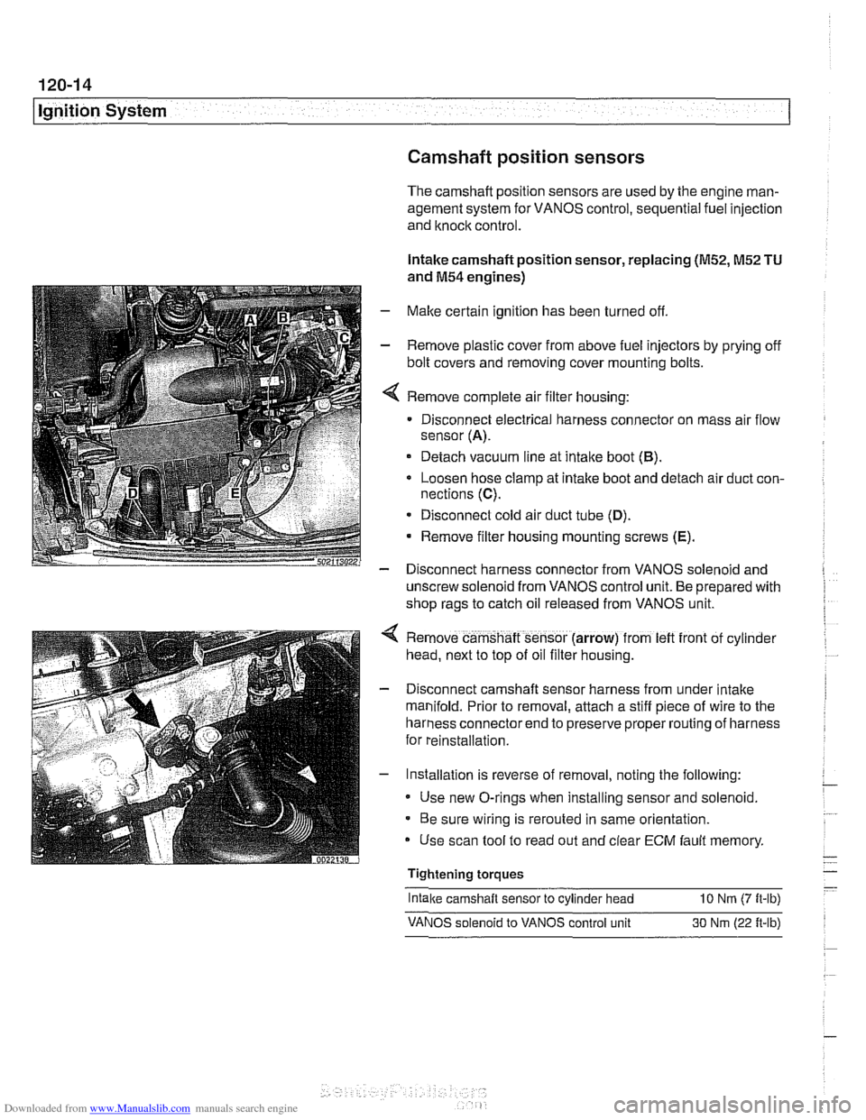
Remove complete air filter housing:
Disconnect electrical harness connector on mass air flow
sensor
(A).
Detach vacuum line at intake boot (B).
Loosen hose clamp at intake boot and detach air duct con-
nections
(C).
* Disconnect cold air duct tube (D).
Remove filter housing mounting screws (E).
- Disconnect harness connector from VANOS solenoid and
unscrew solenoid from VANOS control unit. Be prepared with
shop rags to catch oil released from VANOS unit.
Remove camshaft sensor (arrow) from
left front of cyl~nder
head, next to top of oil filter housing.
Disconnect camshaft sensor harness from under intake
manifold. Prior to removal, attach a stiff piece of wire to the
harness connector end to preserve proper routing of harness
for reinstallation.
Installation is reverse of removal, noting the following:
Use new O-rings when installing sensor and solenoid.
Be sure wiring is rerouted in same orientation.
Use scan tool to read out and clear
ECM fault memory
Tightening torques
-
Intake camshaft sensor to cylinder head 10 Nrn (7 ft-lb)
VANOS solenoid to VANOS control unit 30 Nm (22 ft-lb)
Page 363 of 1002
Downloaded from www.Manualslib.com manuals search engine
120-15
Ignition system1
Exhaust camshaft position sensor, replacing
(M52 TU and M54 engines)
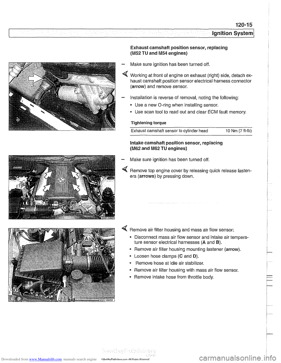
- Make sure ignition has been turned off.
4 Working at front of engine on exhaust (right) side, detach ex-
haust camshaft position sensor electrical harness connector
(arrow) and remove sensor.
- Installation is reverse of removal, noting the following:
Use a new O-ring when installing sensor.
- Use scan tool to read out and clear ECM fault memory.
Tightening torque
Exhaust camshaft sensor
to cylinder head 10 Nm (7 ft-lb)
Intake camshaft position sensor, replacing
(M62 and M62 TU engines)
- Make sure ignition has been turned off
4 Remove top engine cover by releasing quick release fasten-
ers (arrows) by pressing down.
4 Remove air filter housing and mass air flow sensor:
Disconnect mass air flow sensor and
intalte air tempera-
ture sensor electrical harnesses
(A and B).
Remove air filter housing mounting fastener (arrow).
Loosen hose clamps
(C and D).
Remove hose at idle air stabilizer.
Remove air filter housing with mass air flow sensor.
- Remove intalte hose from throttle body.
Page 364 of 1002
Downloaded from www.Manualslib.com manuals search engine
120-1 6
Ignition System
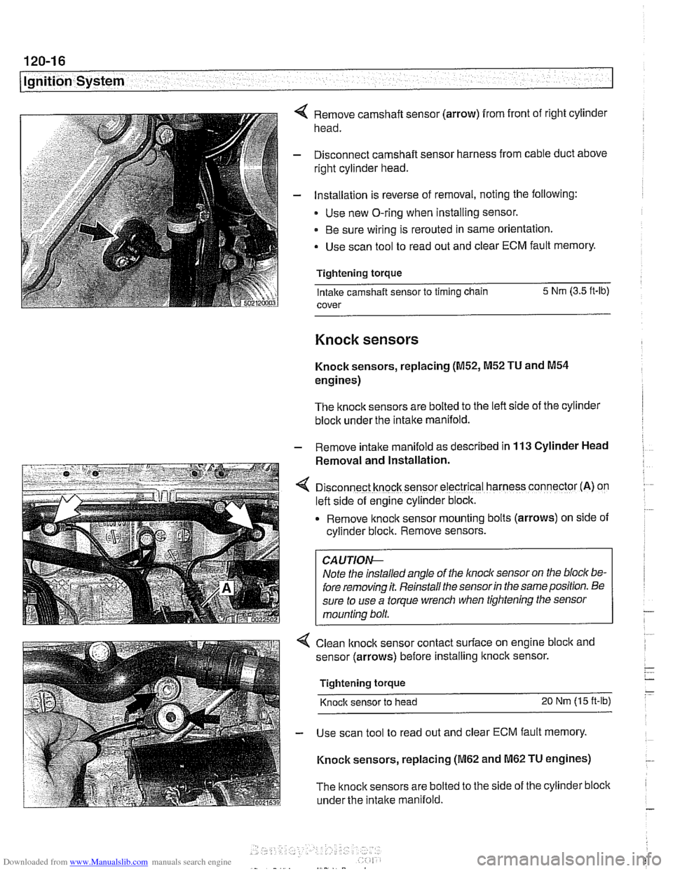
Remove camshaft sensor (arrow) from front of right cylinder
head.
Disconnect camshaft sensor harness from cable duct above
right cylinder head.
Installation is reverse of removal, noting the following:
Use new O-ring when installing sensor.
Be sure wiring is rerouted in same orientation.
Use scan tool to read out and clear ECM fault memory.
Tightening torque Intake camshaft sensor to timing chain 5 Nm
(3.5 ft-lb)
cover
Knock sensors
Knock sensors, replacing (M52, M52 TU and M54
engines)
The knock sensors are bolted to the left side of the cylinder
block under the intake manifold.
- Remove intalte manifold as described in 113 Cylinder Head
Removal and Installation.
D~sconnect knock sensor electrical harness connector (A) on
left side of engine cylinder block.
Remove knock sensor
mount~ng bolts (arrows) on side of
cyllnder block. Remove sensors.
Note the installed angle of the
lnocl~ sensor on the bloc/( be-
fore removing it. Reinstall the sensor
in the same position. Be
sure to use a torque wrench when tightening the sensor
mounting bolt.
< Clean lknock sensor contact surface on engine bloclc and
sensor (arrows) before installing
ltnock sensor.
Tightening torque
Knock sensor to head 20 Nm (15 ft-lb)
- Use scan tool to read out and clear ECM fault memory.
Knock sensors, replacing
(M62 and M62 TU engines)
The
knock sensors are bolted to the side of the cylinder block
under the
intake manifold.