Cylinder BMW 540i 1999 E39 Workshop Manual
[x] Cancel search | Manufacturer: BMW, Model Year: 1999, Model line: 540i, Model: BMW 540i 1999 E39Pages: 1002
Page 365 of 1002
Downloaded from www.Manualslib.com manuals search engine
Ignition System
Remove intake manifold as described in 113 Cylinder Head
Remaval and Installation.
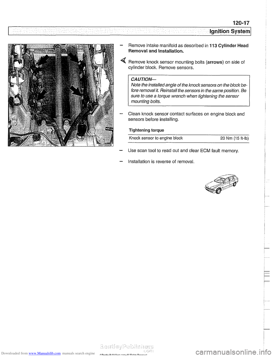
Remove knock sensor mounting bolts (arrows) on side of
cylinder block. Remove sensors.
I CAUTION- I
Note the installedangle of the knock sensors on the bloclt be-
fore removalit. Reinstall the sensors in the same position. Be
sure to use
a torque wrench when tightening the sensor
mounting bolts.
Clean
lknoclc sensor contact surfaces on engine bloclc and
sensors before installing.
Tightening torque
Knock sensor to engine
bloclc 20 Nm (15 ft-lb)
- Use scan tool to read out and clear ECM fault memory.
- Installation is reverse of removal.
Page 367 of 1002
Downloaded from www.Manualslib.com manuals search engine
121-1
121 Battery. Starter. Alternator
General ........................... .I2 1.2
Special tools ........................ .I2 1.2
Engine electrical system ............... .I2 1.2
Battery Safety Terminal ............... .I2 1.3
Warnings and cautions ................. 121 -4
Battery ............................ 121-5
Battery testing ...................... .I2 1.5
Hydrometer testing ................... .I2 1.5
Battery open-circuit voltage test ......... .I2 1.6
Battery load voltage test ................ 121 -6
Closed-circuit current measurement ..... .I2 1.7
Battery charging ...................... 121 -9
Battery safety terminal, replacing ......... 121-9
Alternator (generator) ............. .I2 1.10
Alternator. basic .................... .I2 1.11
Alternator with multi-function
control (MFR)
...................... .I2 1.11
Water-cooled alternator ............... 121 -12
Charging System Troubleshooting . 121-12
Charging system quick-check .......... 121-13
Charging system. checking ............ 121-13
Alternator. removing and installing
(6-cylinder engine)
.................. 121 -1 5
Alternator. removing and installing
(M62 engine. air cooled)
.............. 121-16
Alternator. removing and installing
(M62 TU engine. water cooled) ......... 121-1 8
Starter ........................... 121 -1 9
Starter troubleshooting ............... 121 -1 9
Starter. removing and installing
(6-cylinder engine)
.................. 121-20
Starter. removing and installing
(V-8 engine)
........................ 121 -21
Solenoid switch. removing and installing . . 121-23
Page 377 of 1002
Downloaded from www.Manualslib.com manuals search engine
121-11
Battery, Starter, ~lternatorl
Alternator 1997 - 98 5281 1997 540i
/-- -----,
I'
-----------
F15 / 7.5A/ :
&.. .... , 30 1 Xi0015
Battery
Hol in run 61 E (D+) Alternator
and stsrt
lBL
(Generator)
1 .--------,charge , . I , indicator I xGoli i
I <"9,7,a,T
Alternator, basic
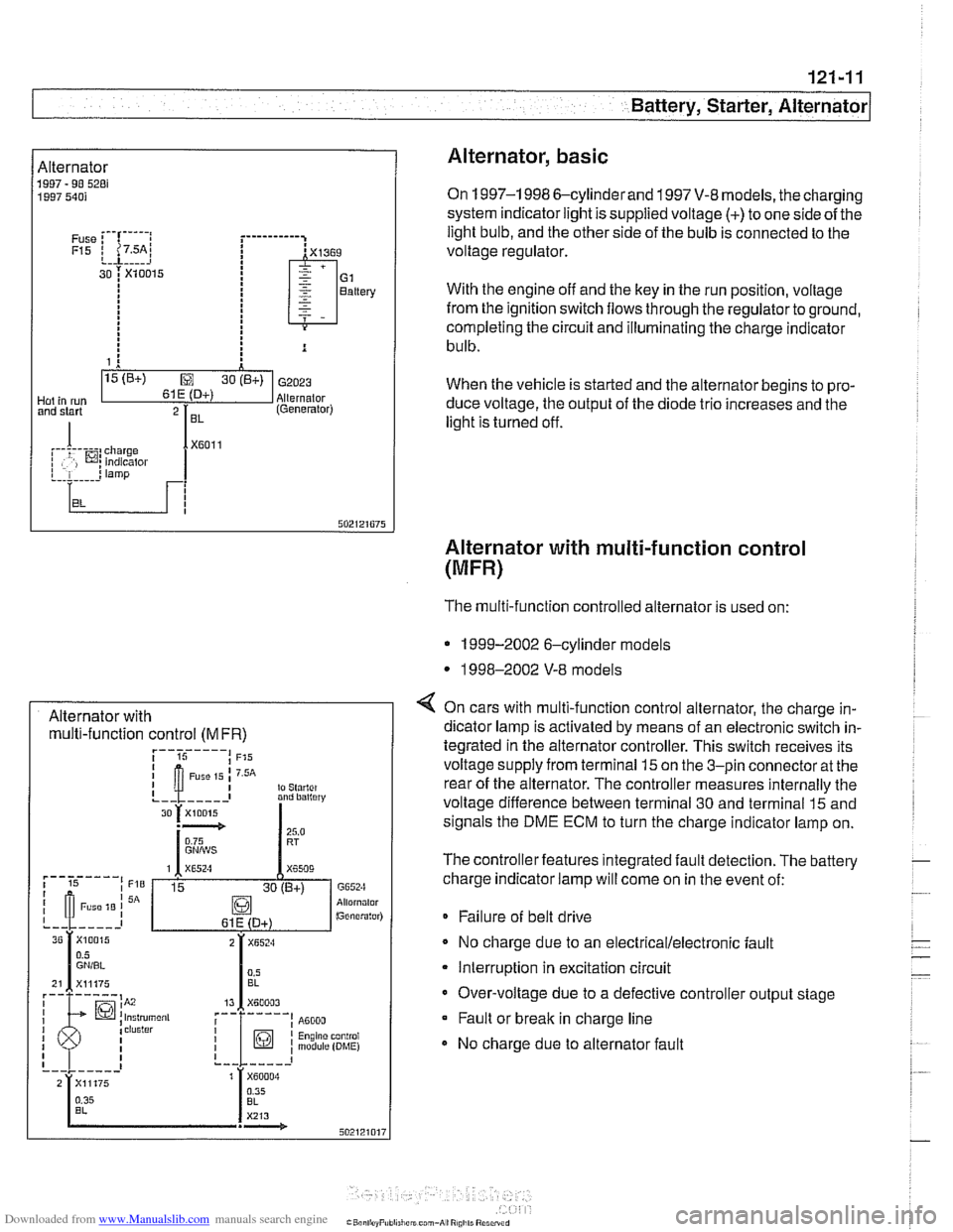
On 1997-1 998 6-cylinderand 1997 V-8 models, the charging
system indicator light is supplied voltage
(+) to one side of the
light bulb, and the other side of the bulb is connected to the
voltage regulator.
With the engine off and the key in the run position, voltage
from the ignition switch flows through the regulator to ground,
completing the circuit and illuminating the charge indicator
bulb.
When the vehicle is started and the alternator begins to pro-
duce voltage, the output of the diode trio increases and the
light is turned off.
Alternator with multi-function control
(MFR)
Alternator with multi-function control
(MFR)
The multi-function controlled alternator is used on:
* 1999-2002 6-cylinder models
* 1998-2002 V-8 models
4 On cars with multi-function control alternator, the charge in-
dicator lamp is activated by means of an electronic switch in-
tegrated in the alternator controller. This switch receives its
voltage supply from terminal
15 on the 3-pin connector at the
rear of the alternator. The controller measures internally the
voltage difference between terminal 30 and terminal
15 and
signals the DME ECM to turn the charge indicator lamp on.
The controller features integrated fault detection. The battery
charge indicator lamp will come on in the event of:
* Failure of belt drive
No charge due to an
electrical/electronic fault
Interruption in excitation circuit
Over-voltage due to a defective controller output stage Fault or break in charge line
No charge due to alternator fault
Page 378 of 1002
Downloaded from www.Manualslib.com manuals search engine
Battery, Starter, Alternator
Water-cooled alternator
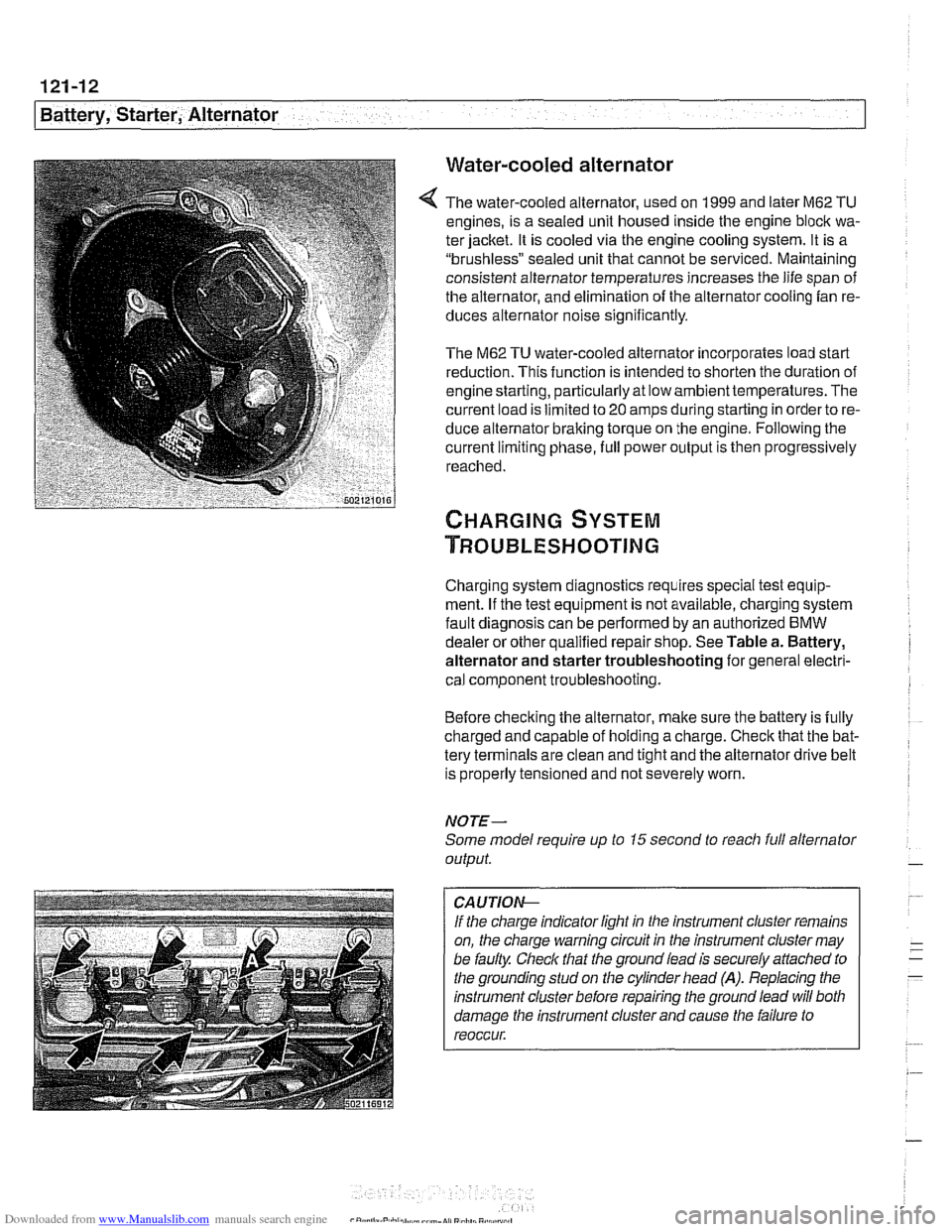
The water-cooled alternator, used on 1999 and later M62 TU
engines, is a sealed unit housed inside the engine block wa-
ter jacket. It is cooled via the engine cooling system. It is a
"brushless" sealed unit that cannot be serviced. Maintaining
consistent alternator temperatures increases the life span of
the alternator, and elimination of the alternator cooling fan re-
duces alternator noise
significantly.
The M62 TU water-cooled alternator incorporates load start
reduction. This function is intended to shorten the duration of
engine starting, particularly at low ambienttemperatures. The
current load is limited to
20 amps during starting in order to re-
duce alternator braking torque on the engine. Following the
current limiting phase, full power output is then progressively
reached.
Charging system diagnostics requires special test equip-
ment. If the test equipment is not available, charging system
fault diagnosis can be performed by an authorized
BMW
dealer or other qualified repair shop. See Table a. Battery,
alternator and starter troubleshooting for general electri-
cal component troubleshooting.
Before checking the alternator, make sure the battery is fully
charged and capable of holding a charge. Check that the bat-
tery terminals are clean and tight and the alternator drive belt
is properly tensioned and not severely worn.
NOTE-
Some model require up to 15 second to reacli full alternator
output.
CA UTIOG
If the charge indicator light in the instrument cluster remains
on, the charge warning circuit in the instrument cluster may
be faulty. Check that the ground lead is securely
affached to
the grounding stud on the cylinder head
(A). Replacing the
instrument cluster before repairing the ground lead will both
damage the instrument cluster and cause the failure to
reoccur.
Page 379 of 1002
Downloaded from www.Manualslib.com manuals search engine
Battery, Starter, ~lternatorl
Charging system quick-check
Use a digital multimeter to measure voltage across the bat-
tery terminals with key off and then again with engine running.
Battery voltage should be about 12.6 volts with key off and be-
tween 13.5 and 14.5 volts with engine running.
NOTE-
The regulated voltage (engine running) should be between
13.2 and 14.5, depending on temperature andoperating con-
ditions.
If the voltage is higher than 14.8, the voltage regula-
tor or
mulitfunction controller is most likely faulty
Check for clean and tight battery cables. Check ground cable
running from negative
(-) battery terminal to chassis and
ground cable running from engine to chassis. Check alterna-
tor drive belt condition and tension.
Charging system, checking
CAUTIOI\C
* Do not disconnect the battery while the engine is running.
Damage to the alternator and/or engine electronic systems
may result.
Only use a digital multimeter when testing charging
system components.
--7
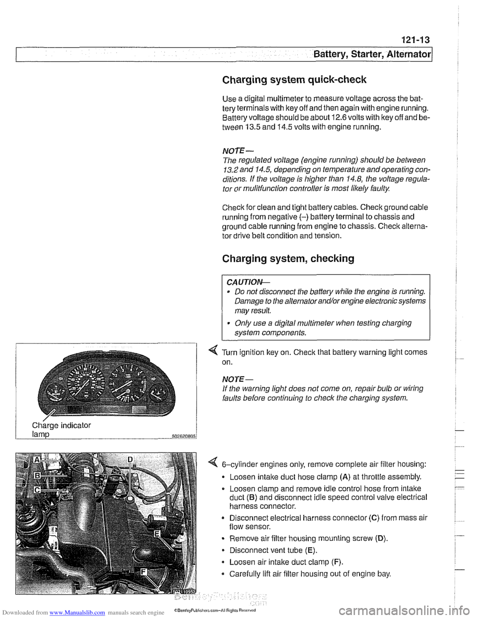
4 Turn ignition key on. Check that battery warning light comes
on.
NOTE-
If the warning light does not come on, repair bulb or wiring
faults before continuing to checlc the charging system.
/ Charge indicator
502820805
4 6-cylinder engines only, remove complete air filter housing:
Loosen
intake duct hose clamp (A) at throttle assembly.
Loosen clamp and remove idle control hose from intake
duct
(B) and disconnect idle speed control valve electrical
harness connector.
Disconnect electrical harness connector
(C) from mass air
flow sensor.
Remove air filter housing mounting screw
(D).
Disconnect vent tube (E).
Loosen air intake duct clamp (F).
Carefully lift air filter housing out of engine bay.
Page 380 of 1002
Downloaded from www.Manualslib.com manuals search engine
- -
/Battery, Starter, Alternator -- - -. - --I
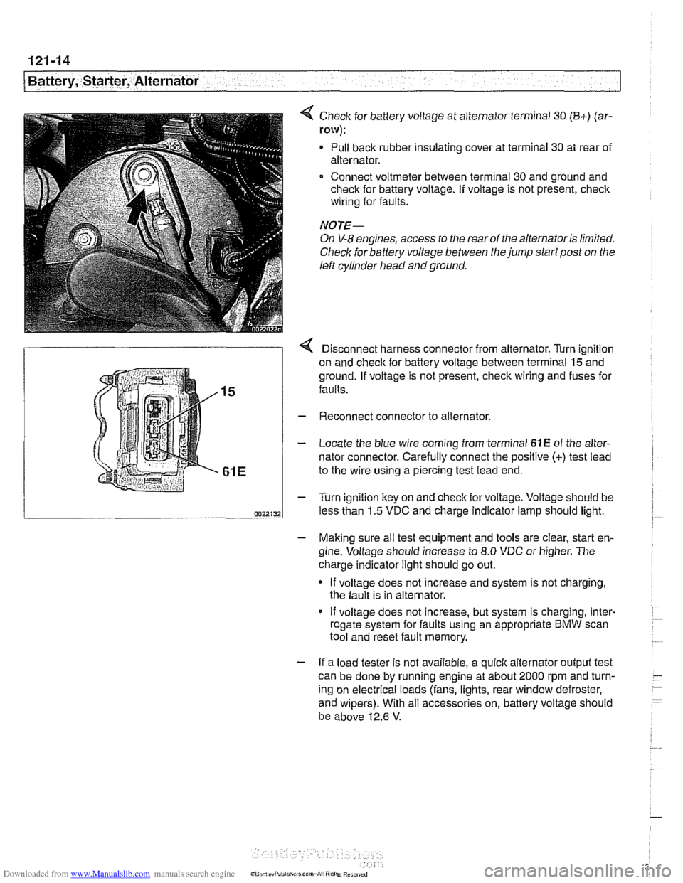
< Check for battery voltage at alternator terminal 30 (B+) (ar-
row):
Pull back rubber insulating cover at terminal 30 at rear of
alternator.
Connect voltmeter between terminal 30 and ground and
check for battery voltage.
If voltage is not present, check
wiring for faults.
NOTE-
On V-8 engines, access to the rear of the alternator is limited.
Check for battery voltage between the jump start post on the
left cylinder head and ground.
r Disconnect harness connector from alternator. Turn ianition
on and check for battery voltage between terminal
lgand
ground. If voltage is not present, check wiring and fuses for
faults.
Reconnect connector to alternator.
Locate the blue wire coming from terminal
61E of the alter-
nator connector. Carefully connect the positive
(+) test lead
to the wire using a piercing test lead end.
Turn ignition key on and check for voltage. Voltage should be
less than 1.5 VDC and charge indicator lamp should light.
- Making sure all test equipment and tools are clear, start en-
gine. Voltage should increase to
8.0 VDC or higher. The
charge indicator light should go out.
If voltage does not increase and system is not charging,
the fault is in alternator.
- If voltage does not increase, but system is charging, inter- - roaate svstem for faults usina an appropriate BMW scan - .. . tool and'reset fault memory.
- If a load tester is not available, a quick alternator output test
can be done by running engine at about 2000 rpm and turn-
- -
ing on electrical loads (fans, lights, rear window defroster, -
- and wipers). With all accessories on, battery voltage should
be above 12.6
V.
Page 381 of 1002
Downloaded from www.Manualslib.com manuals search engine
Battery, Starter, ~lternatorl
Alternator, removing and installing
(6-cylinder engine)
A replacement alternator should have the same rating as the
original. Alternator manufacturer and ampere rating are nor-
mally marked on the alternator housing.
- Disconnect negative (-) battery cable.
CAUTION-
Prior to disconnecting the batteg read the battery discon-
nection cautions given
in 001 General Warnings and Cau-
I tions.
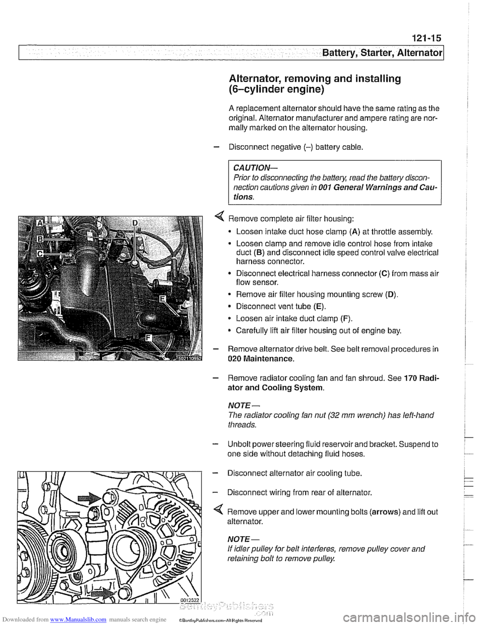
Remove complete air filter housing:
Loosen intake duct hose clamp
(A) at throttle assembly.
Loosen clamp and remove idle control hose from intake
duct
(B) and disconnect idle speed control valve electrical
harness connector.
Disconnect electrical harness connector
(C) from mass air
flow sensor.
* Remove air filter housing mounting screw (D),
Disconnect vent tube (E).
Loosen air intake duct clamp (F).
Carefully lifl air filter housing out of engine bay.
Remove alternator drive belt. See belt removal procedures in
020 Maintenance.
- Remove radiator cooling fan and fan shroud. See 170 Radi-
ator and Cooling System.
NOTE-
The radiator cooling fan nut (32 mm wrench) has left-hand
threads.
- Unbolt power steering fluid reservoir and bracket. Suspend to
one side without detaching fluid hoses.
- Disconnect alternator air cooling tube.
- Disconnect wiring from rear of alternator.
'4 Remove upper and lower mounting bolts (arrows) and lift
alternator.
If idler pulley for belt interferes, remove pulley cover and
retaining bolt to remove pulley. out
Page 386 of 1002
Downloaded from www.Manualslib.com manuals search engine
I Battery, Starter, Alternator
- Check for battery voltage at terminal 50 of starter motor with
key in start position. If voltage is not present, check wiring be-
tween ignition switch and starter terminal. Check the EWS
system and other inputs that disrupt terminal
56 to the start-
er. See ELE Electrical
Wiring Diagrams. If voltage is
present and no other visible wiring faults can be found, prob-
lem is most likely in starter motor.
Starter, removing and installing
(6-cylinder engine)
The starter is removed from below. Access to starter bolts is
difficult. Be sure to have the proper tools on hand before pro-
ceeding.
NOTE-
Access to the starter wiring is very limited. Forbetteraccess,
it may be necessary to remove the intake manifold.
- Disconnect negative (-) battery cable.
CAUTIOI\C
Prior to disconnecting the battern read the baltery discon-
nection cautions
in OOlGeneral Cautions and Warnings.
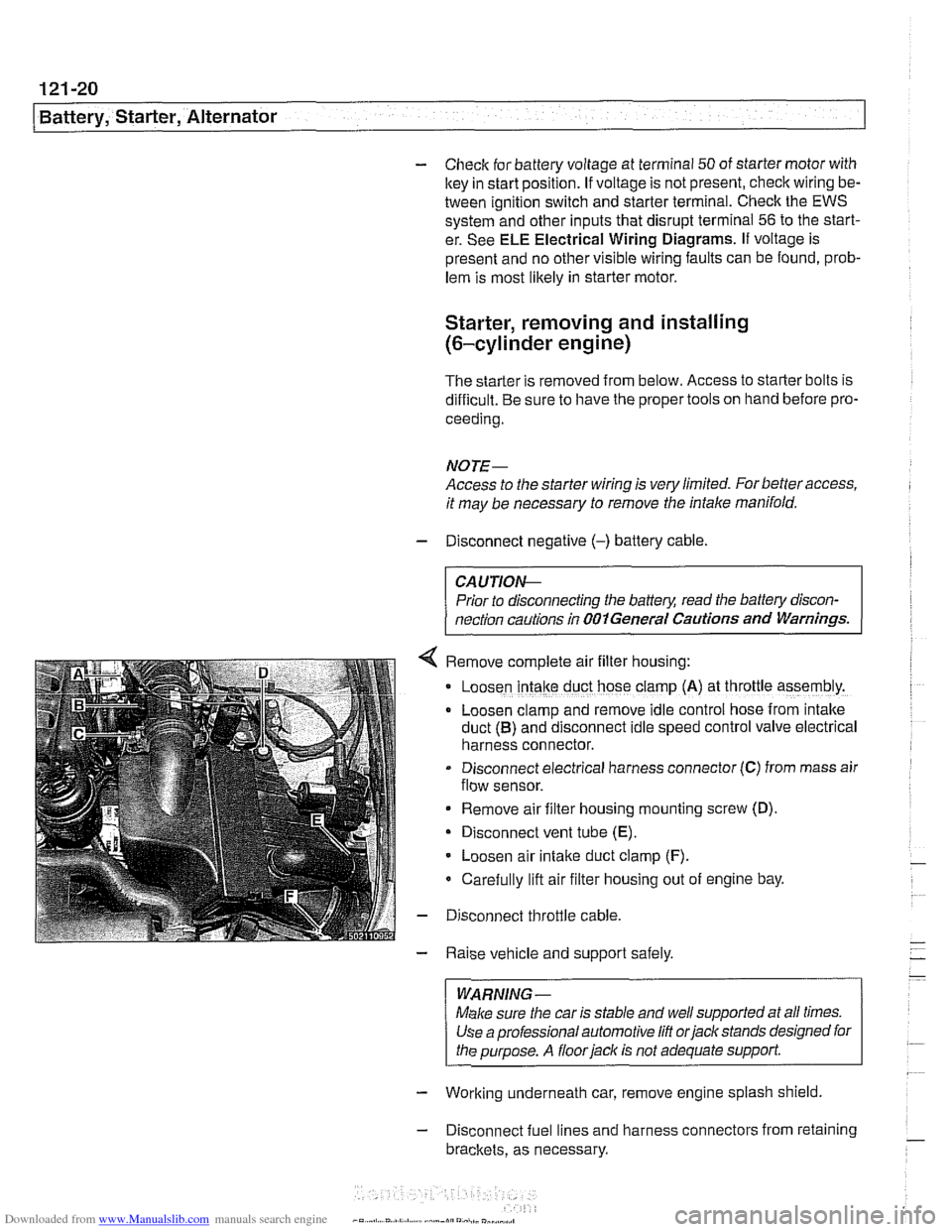
Remove complete air filter hous~ng:
Loosen intake duct hose clamp (A) at throttle assembly.
Loosen clamp and remove idle control hose from intake
duct
(B) and disconnect idle speed control valve electrical
harness connector.
Disconnect electrical harness connector
(C) from mass air
flow sensor.
Remove air filter housing mounting screw (D)
Disconnect vent tube
(E).
Loosen air intake duct clamp (F).
Carefully lift air filter housing out of engine bay.
Disconnect throttle cable.
Raise vehicle and support safely.
WARNING-
Make sure the car is stable and well supported at all times.
Use a professional automotive
lift orjack stands designed for
the purpose. A
floorjaclc is not adequate support
- Working underneath car, remove engine splash shield
- Disconnect fuel lines and harness connectors from retaining
brackets, as necessary.
Page 400 of 1002
Downloaded from www.Manualslib.com manuals search engine
130-1 0
Fuel Injection
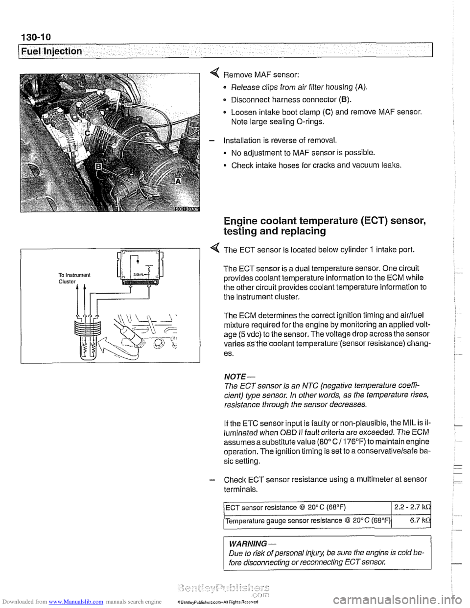
Remove MAF sensor:
Release clips from air filter housing
(A).
Disconnect harness connector (B).
Loosen intake boot clamp (C) and remove MAF sensor.
Note large sealing O-rings.
Installation is reverse of removal.
No adjustment to MAF sensor is possible.
Check intake hoses for cracks and vacuum leaks.
Engine coolant temperature (ECT) sensor,
testing and replacing
R
1 -4 The ECT sensor is located below cylinder 1 intake port
The ECT sensor is a dual temperature sensor. One circuit
provides coolant temperature information to the ECM while
the other circuit provides coolant temperature information to
the instrument cluster.
The ECM determines the correct ignition timing and
airlfuel
mixture required for the engine by monitoring an applied volt-
age
(5 vdc) to the sensor. The voltage drop across the sensor
varies as the coolant temperature (sensor resistance) chang-
es.
NOTE-
The ECT sensor is an NTC (negative temperature coeffi-
cient) type sensor. in other words, as the temperature rises,
resistance through the sensor decreases.
If the ETC sensor input is faulty or non-plausible, the MIL is il-
luminated when
OED II fault criteria are exceeded. The ECM
assumes asubstitute value
(80°C1 176°F) to maintainengine
operation. The ignition timing is set to a
conse~ativelsafe ba-
sic setting.
- Check ECT sensor resistance using a multimeter at sensor
terminals.
-
WARNING -
Due to risk of personal injury, be sure the engine is cold be-
fore disconnecting or reconnecting ECT sensor.
ECT sensor resistance @ 20" C (68°F) 2.2 - 2.7
Temperature gauge sensor resistance @ 20°C (~B"F)( 6.7 k
Page 401 of 1002
Downloaded from www.Manualslib.com manuals search engine
Fuel Injection
CAUTION-
Be sure ignition is OFF before disconnecting or reconnecting
DME system components.
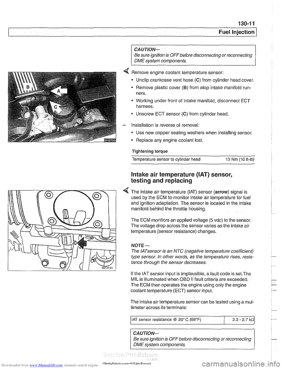
Remove engine coolant temperature sensor:
Unclip crankcase vent hose
(C) from cylinder head cover.
Remove plastic cover
(6) from atop intake manifold run-
ners.
Working under front of intake manifold, disconnect ECT
harness.
Unscrew ECT sensor
(C) from cylinder head.
Installation is reverse of removal:
Use new copper sealing washers when installing sensor.
Replace any engine coolant lost.
Tightening torque
Temperature sensor to cylinder head
13 Nm (10 it-lb)
Intake air temperature ([AT) sensor,
testing and replacing
4 The intake air temperature (IAT) sensor (arrow) signal is
used by the ECM to monitor intake air temperature for fuel
and
igntion adaptation. The sensor is .ocared in rne 'ntane
man:lold behind the throttle housng.
The ECM monitors an applied voltage (5 vdc) to the sensor
The voltage drop across the sensor varies as the intake air
temperature (sensor resistance) changes.
NOJE-
The IATsensor is an NTC (negative temperature coefficient)
type sensor. In other words, as the temperature rises, resis-
tance through the sensor decreases.
If the IAT sensor input is implausible, a
fault code is set.The
MIL is illuminated when OED II fault criteria are exceeded.
The ECM then operates the engine using only the engine
coolant temperature (ECT) sensor input.
The intake air temperature sensor can be tested using a
mul-
timeter across its terminals:
/ IAT sensor resistance @ 20" C (68°F) / 2.2 - 2.7 lkCk
~ -- ~~ -
CAUTION--
Be sure ignition is
OFFbefore disconnecting or reconnecting
DME system components.