Cylinder BMW 540i 1999 E39 Workshop Manual
[x] Cancel search | Manufacturer: BMW, Model Year: 1999, Model line: 540i, Model: BMW 540i 1999 E39Pages: 1002
Page 467 of 1002
Downloaded from www.Manualslib.com manuals search engine
Fuel lnjection
I 1- I
4 /output l~em~erature signal. E-box fan I E-box fan
Connector
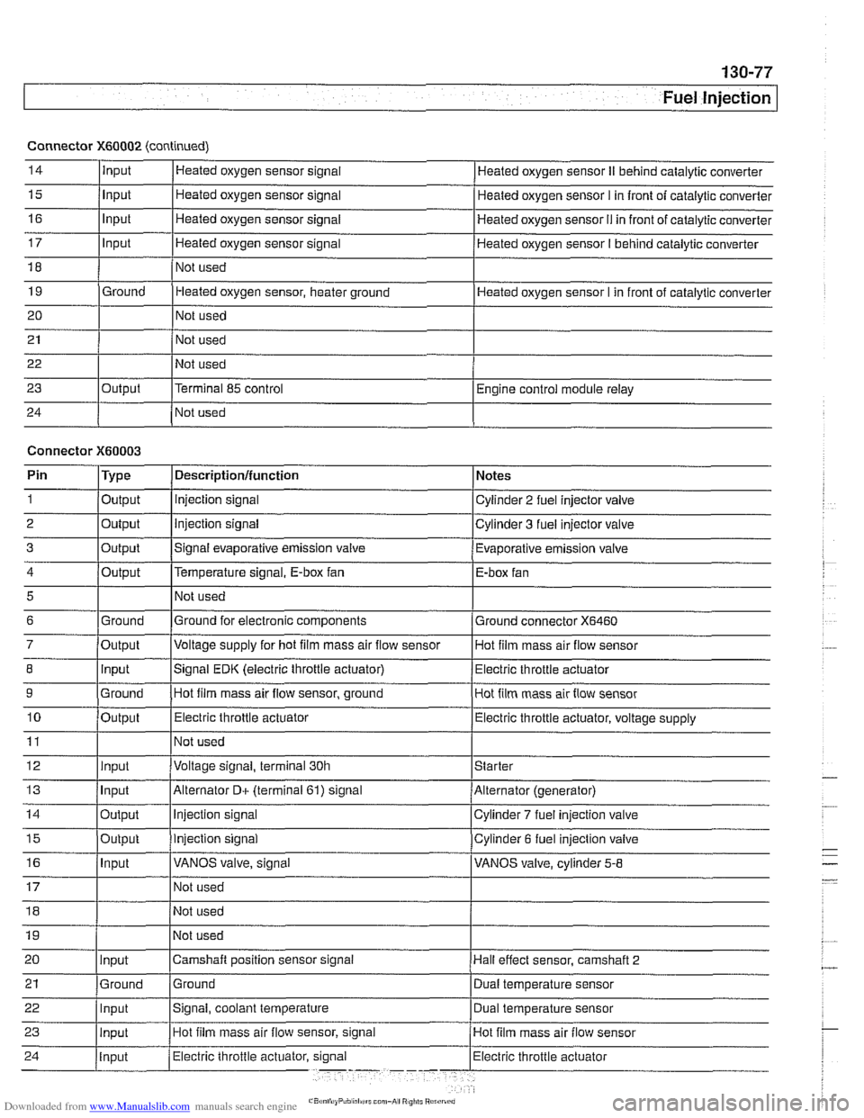
X60002 (continued)
14
15
16
17
18
19
20
21
22
23
24
5
6
7
8
9
10
11
12
13
14
15
16
Input
Input
Input
Input
Ground
Output Heated
oxygen sensor signal
Heated oxygen sensor signal
Heated oxygen sensor signal
Heated oxygen sensor signal
Not used
Heated oxygen sensor, heater ground
Not used
Not used
Not used
Terminal 85 control
Not used Heated oxygen sensor
II behind catalytic converter
Heated oxygen sensor
I in front of catalytic converter
Heated oxygen sensor
I1 in front of catalytic converter
Heated oxygen sensor
I behind catalytic converter
Heated oxygen sensor I in front of catalytic converter
Engine control module relay
Connector
X60003
Ground
Output Input
Ground
Output
Input
Input
Output
Output
Input
Pin 1
2
3
Not used
Ground for electronic components
Voltage supply for hot
film mass air flow sensor
Signal EDK (electric throttle actuator) Hot film mass air flow sensor, ground
Electric throttle actuator
Not used
Voltage signal, terminal 30h
Alternator
D+ (terminal 61) signal
Injection signal
Injection signal
VANOS valve, signal
Type
Output
Output
Output
Ground connector
X6460
Hot film mass air flow sensor
Electric throttle actuator
Hot film mass air flow sensor
Electric throttle actuator, voltage supply
Starter
Alternator (generator)
Cylinder
7 fuel injection valve
Cylinder 6 fuel injection valve
VANOS valve, cylinder
5-8
Descriptionlfunction
Injection signal
Injection signal
Signal evaporative emission valve Notes
Cylinder 2 fuel injector valve
Cylinder 3 fuel injector valve
Evaporative emission valve
Page 468 of 1002
Downloaded from www.Manualslib.com manuals search engine
I Fuel Injection
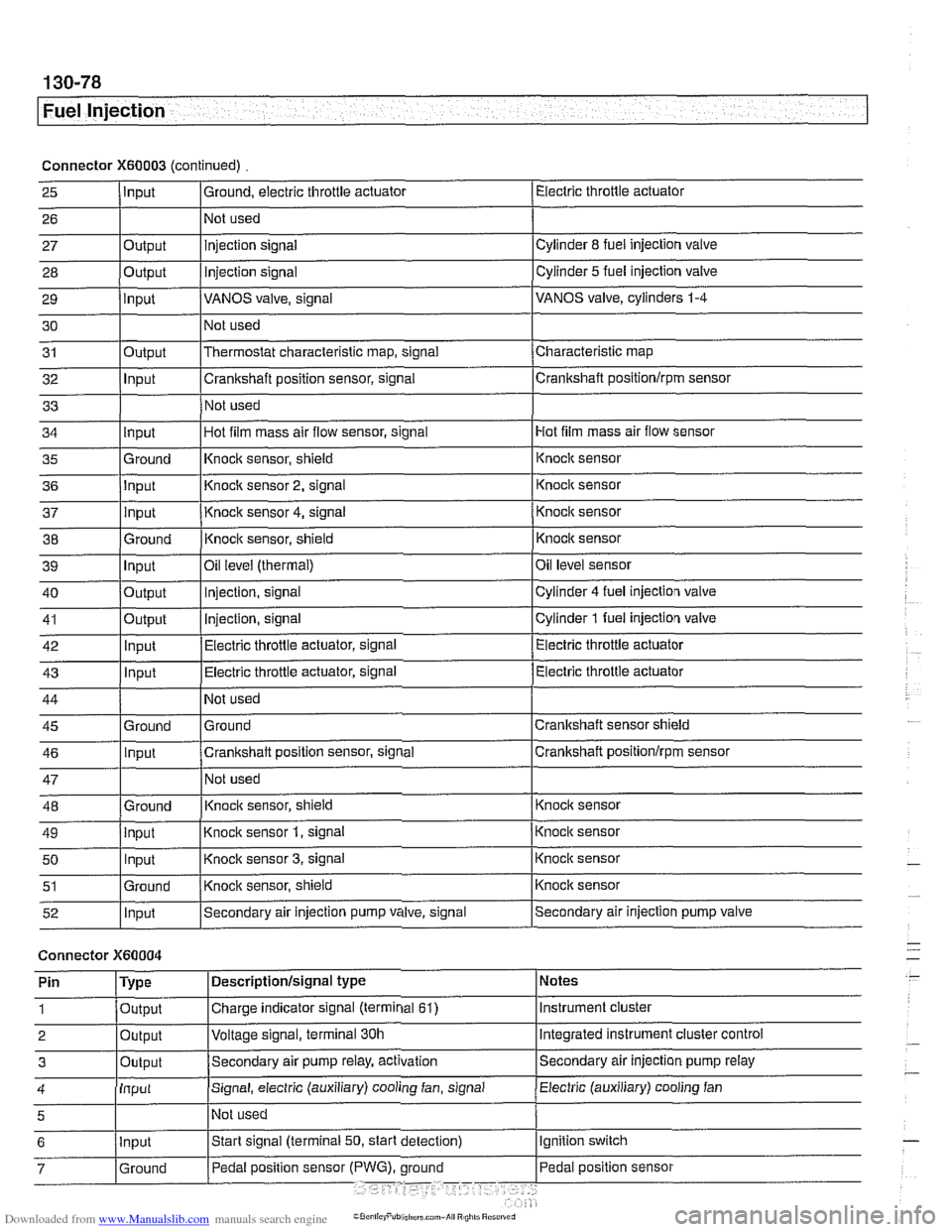
Connector X60003 (continued) Electric throttle actuator
25
- 27 28
29
30
31
32
33
I I I
36 jlnput I Knoclc sensor 2, signal 1 Knock sensor
I I I
Input
26
Output
Output
input
Output
Input
I ' I . I
43 1 ln~ut I Electric throttle actuator, signal (Electric throttle actuator
Ground, electric throttle actuator
1 Not
used
Hot film mass air flow sensor
34
- 37
38
39
40
41
42
injection signal
Injection
signal
VANOS valve, signal
Not used
Thermostat characteristic map, signal
Crankshaft position sensor, signal
Not used
35 l~round I~nock sensor, shield 1 ~nock sensor
Cylinder
8 fuel injection valve
Cylinder
5 fuel injection valve
VANOS valve, cylinders
1-4
Characteristic map
Crankshaft positionlrpm sensor
input
input
Ground
Input
Output
Output
Innut
Hot film mass air flow sensor, signal
I
44
45 46
47
48
49
50
51
52
Connector )(GO004
Knock sensor 4, signal
Knock sensor, shield
Oil
level (thermal)
Injection, signal
Injection, signal
Electric throttle actuator, signal
Not used
Ground
Crankshaft position sensor, signal
Not used
Knoclc sensor, shield
Knock sensor
1, signal
Knock sensor
3, signal
Knock sensor, shield
Secondary air injection pump valve, signal
'
Ground
Input
Ground
input Input
Ground
Input
I' I ... I . ~
Knock sensor
Knocic sensor
Oil level sensor
Cylinder
4 fuel injection valve
Cylinder
1 fuel injection valve
Electric throttle actuator
Crankshaft sensor shield
Crankshaft
positionlrprn sensor
Knock sensor
Knock sensor
Knock sensor
Knock sensor
Secondary air injection pump valve
Notes
Instrument cluster
Integrated instrument cluster control
Secondary air injection pump
relay
Pin
1
2
3
Electric (auxiliary) cooling fan 4
Type
Output
Output
Outout
Descriptionlsignal type
Charge indicator signal (terminal
61)
Voltage signal, terminal 30h
Secondam air pump relay, activation
Input
5
Signal, electric (auxiliary) cooling fan, signal
I~ot used
Page 470 of 1002
Downloaded from www.Manualslib.com manuals search engine
Fuel Injection
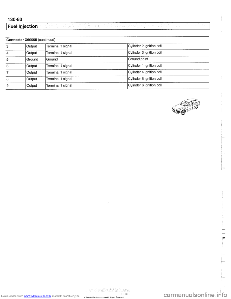
Connector X60005 (continued)
I I I
6 /output l~erminal 1 signal ICylinder 1 ignition coil
Cylinder
2 ignition
coil
Cylinder
3 ignition coil
Ground point
3
4
5
7
8 -- 9
Output
Output
Ground Terminal 1 signal
Terminal
1 signal
Ground
Output
Output
Output Terminal
1 signal
Terminal
1 signal
p
Cylinder 4 ignition coil
Cylinder
5 ignition coil
Cylinder
6 ignition coil
Page 471 of 1002
Downloaded from www.Manualslib.com manuals search engine
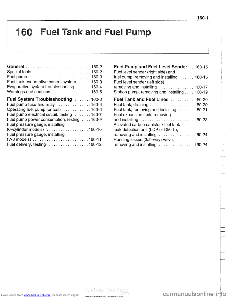
160 Fuel Tank and Fuel Pump
General ........................... .I6 0.2
Special tools ........................ .I6 0.2
Fuel pump ......................... .I6 0.3
Fuel tank evaporative control system ..... .I6 0.3
Evaporative system troubleshooting ..... .I6 0.4
Warnings and cautions ................ .I6 0.5
Fuel System Troubleshooting ...... .I6 0.6
Fuel pump fuse and relay .............. .I6 0.6
Operating fuel pump for tests ........... .I6 0.6
Fuel pump electrical circuit, testing ...... .I6 0.7
Fuel pump power consumption, testing ... .I6 0.9
Fuel pressure gauge, installing
(6-cylinder models)
................. .I6 0.1 0
Fuel pressure gauge, installing
(V-8 models) ....................... .I6 0.1 1
Fuel delivery, testing ................ .I6 0.12
Fuel Pump and Fuel Level Sender . . 160-15
Fuel level sender (right side) and
fuel pump. removing and installing
...... 160-15
Fuel level sender (left side).
removing and installing
............... 160-17
Siphon pump. removing and installing .... 160-1 9
Fuel Tank and Fuel Lines .......... 160-20
Fuel tank. draining ................... 160-20
Fuel tank. removing and installing ....... 160-21
Fuel expansion tank. removing
and installing
....................... 160-23
Activated carbon canister I fuel tank
leak detection unit
(LDP or DMTL).
removing and installing ............... 160-24
Running losses (312-way) valve.
removing and installing
............... 160-24
Page 476 of 1002
Downloaded from www.Manualslib.com manuals search engine
.-- -
/ Fuel Tank and Fuel Pump - .. -. -- 1
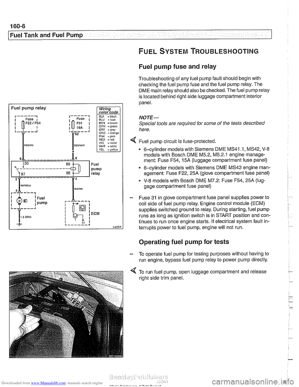
Fuel pump fuse and relay
Troubleshooting of any fuel pump fault should begin with
checking the fuel pump fuse and the fuel pump relay. The
DME main relay should also be checked. The fuel pump relay
is located behind right side luggage compartment interior
panel.
I Fuel pump relay
BLU =blue ERN = blo$,m GRN =groan GRY = grsy ORG =orange PNI< =pink RED =red VIO =violel WHT = wlilte
rk-; I I 1 ECM
I I I 31 8 ,._--___.I
NOTE-
Special tools are required for some of the tests described
here.
4 Fuel pump circu~t is fuse-protected.
0 6-cylinder models with Siemens DME MS41 .I, MS42, V-8
models with Bosch DME M5.2, M5.2.1 englne manage-
ment: Fuse
F54,15A (luggage compartment fuse panel)
6-cylinder models with Siemens DME MS43 engine man-
agement: Fuse
F22,25A (glove compartment fuse panel)
V-8 models with Bosch DME M7.2: Fuse F54,25A (lug-
gage compartment fuse panel)
- Fuse 31 in glove compartment fuse panel supplies power to
coil side of fuel pump relay. Engine control module (ECM)
supplies switched ground to relay. During starting, fuel pump
runs as long as ignition switch is in START position and con-
tinues to run once engine starts. If electrical system fault in-
terrupts power to fuel pump, engine will not run.
. .
Operating fuel pump for tests
- To operate fuel pump for testing purposes without having to
run engine, bypass fuel pump relay to power pump directly.
< To run fuel pump, open luggage compartment and release
right side trim panel.
Page 480 of 1002
Downloaded from www.Manualslib.com manuals search engine
I Fuel Tank and Fuel Pump --
Fuel pressure gauge, installing
(6-cylinder models)
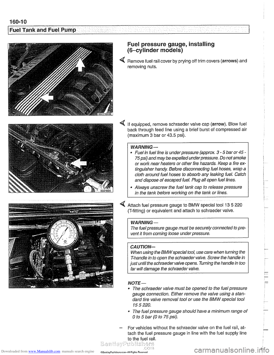
4 Remove fuel rail cover by prying off trim covers (arrows) and
removing nuts.
4 If equipped, remove schraeder valve cap (arrow). Blow fuel
back through feed line using a brief burst of compressed air
(maximum
3 bar or 43.5 psi).
WARNING -
Fuel in fuel line is underpressure (approx. 3 - 5 bar or 45 -
75psi) andmay be expelled underpressure. Do not smoke
or work near heaters or other fire hazards. Keep a fire ex-
tinguisher handy Before disconnecting fuel hoses, wrap a
cloth around fuel hoses to absorb any leaking fuel. Catch
and dispose of escaped fuel. Plug all open fuel lines.
Always unscrew the fuel tank cap to release pressure
in the tank before working on the tank or lines.
4 Attach fuel pressure gauge to BMW special tool 13 5 220
(T-fittlng) or equivalent and attach to schraeder valve.
WARNING -
The fuel pressure gauge must be securely connected to pre-
vent it from
coming loose underpressure.
CAUTION-
When using the BMWspecial tool, use care when turning the
T-handle in to open the schraeder valve. Screw the handle in
just until the schraeder valve opens. Turning the handle in too
far will damage the schraeder valve.
NOTE-
* The schraeder valve must be opened to the fuel pressure
gauge connection. Either remove the valve using a stan-
dard tire valve removal tool or use the BMW special tool
15 5 220.
* The fuel pressure gauge should have a minimum range of
0 to 5 bar (0 to 75 psi).
- For vehicles without the schraeder valve on the fuel rail, at-
tach the fuel pressure gauge in line with the fuel supply line
to the fuel rail.
Page 483 of 1002
Downloaded from www.Manualslib.com manuals search engine
Fuel Tank and Fuel Pump
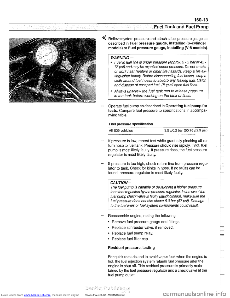
4 Relieve system pressure and attach a fuel pressure gauge as
described in Fuel pressure gauge, installing (6-cylinder
models) or Fuel pressure gauge, installing
(V-8 models).
WARNING-
Fuel in fuel line is under pressure (approx. 3 - 5 bar or 45 -
75psi) and may be expelled underpressure. Do not smoke
or
worlc near heaters or other fire hazards. Keep a fire ex-
tinguisher handy Before disconnecting fuel hoses, wrap a
cloth around fuel hoses to absorb any
leaking fuel. Catch
and dispose of escaped fuel. Plug all open fuel lines.
Always unscrew the fuel tank cap to release pressure
in the tank before
working on the tank or lines.
- Operate fuel pump as described in Operating fuel pump for
tests. Compare fuel pressure to specifications in accompa-
nying table.
Fuel pressure specification
All E39 vehicles 3.5 +0.2 bar (50.76 i2.9 psi)
- If pressure is low, repeat test while gradually pinching off re-
turn hose to fuel tank. Pressure should rise rapidly. If not, fuel
pump is most likely faulty. If pressure rises, the fuel pressure
regulator is most
likely faulty.
- If pressure is too high, checlc return line from pressure regu-
lator to tank. Check for
ltinks in hose. If no faults can be
found, pressure regulator is most likely faulty.
CAUTION-
The fuel pump is capable of developing a higher pressure
than that regulated by the pressure regulator. In the event the
fuel pump checlc valve is faulty (stuck closed), male sure the
I fuel pressure does not rise above 6.0 bar (87psi). Damage
to the fuel lines or fuel system components could result.
- Reassemble engine, noting the following:
Remove fuel pressure gauge and fittings.
Replace schraeder valve, if removed
Replace fuel pump relay.
Replace fuel filler cap.
Residual pressure, testing
For quick restarts and to avoid vapor lock when the engine is
hot, the fuel injection system retains fuel pressure after the
engine is shut off. This residual pressure is primarily
rnain-
tained by the fuel pressure regulator and a checlc valve at the
fuel pump
outlet.
Page 484 of 1002
Downloaded from www.Manualslib.com manuals search engine
. .
I Fuel Tank and Fuel Pump I
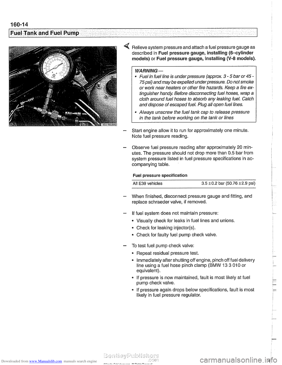
4 Relieve system pressure and attach afuel pressure gauge as
described in Fuel pressure gauge, installing (6-cylinder
models) or Fuel pressure gauge, installing
(V-8 models).
WARNING -
Fuel in fuel line is underpressure (approx. 3 - 5 bar or45 -
75psi) and may be expelled underpressure. Do not smoke
or work near heaters or other fire hazards. Keep a fire ex-
tinguisher handy. Before disconnecting fuel hoses, wrap a
cloth around fuel hoses to absorb any leaking fuel. Catch
and dispose of escaped fuel. Plug all open fuel lines.
. Always unscrew the fuel tank cap to release pressure
in the tank before working on the tank or lines
- Start engine allow it to run for approximately one minute.
Note fuel pressure reading.
- Observe fuel pressure reading after approximately 20 mln-
utes. The pressure should not drop more than 0.5 bar from
system pressure listed in fuel pressure specifications in ac-
companying table.
Fuel pressure specification
Ail
E39 vehicles 3.5 i-0.2 bar (50.76 i2.9 psi)
- When finished, disconnect pressure gauge and fitting, and
replace schraeder valve, if removed.
- If fuel system does not maintain pressure:
Visually check for leaks in fuel lines and unions,
Check for leaking
injector(s).
Check for faulty fuel pump check valve.
- To test fuel pump check valve:
Repeat residual pressure test.
Immediately aftershutting off engine, pinch off fuel delivery
line using a fuel hose pinch clamp (BMW
13 3 010 or
equivalent).
If pressure is now maintained, fault is most likely at fuel
pump check valve.
If pressure again drops below specifications, fault is most
likely in fuel pressure regulator.
Page 497 of 1002
Downloaded from www.Manualslib.com manuals search engine
176 Radiator and Cooling System
General ........................... .I7 0.2
Special tools
........................ .I7 0.2
Cooling system overview
(M52 TU shown. others similar) ......... .I7 0.3
Coolant pump
....................... .I7 0.3
Thermostat
......................... .I7 0.3
Mechanical thermostat (M52 engine)
..... .I7 0.4
Electrically heated thermostat
.......... .I7 0.4
Radiator and expansion tank
........... .I7 0.4
Mechanical cooling fan with viscous clutch
.I7 0.4
Electric (auxiliary) cooling fan ........... .I7 0.4
Transmission fluid heat exchanger
....... .I7 0.5
Warnings and cautions
................ .I7 0.7
Troubleshooting ................... .I7 0.7
Cooling system inspection
............. .I7 0.8
Cooling system pressure test
........... .I7 0.9
Combustion chamber leak test
......... .I7 0.10
Thermostat
........................ .I7 0.1 0
Cooling System Service ........... 170-10
Coolant. draining and filling
(6-cylinder models)
.................. 170-1 0
Coolant. draining and filling (V-8 models)
. 170-12
Cooling system. bleeding
............. 170-14
Mechanical (viscous clutch) cooling fan.
removing and installing
............... 170-14
Electric cooling fan.
removing and installing
............... 170-15
Thermostat. removing and installing
(M52engine) ....................... 170-16
Thermostat. removing and installing
(M52 TU or M54 engine) .............. 170-17
Thermostat. removing and installing (V-8 models)
....................... 170-1 8
Coolant pump. replacing (6-cylinder models)
.................. 170-1 9
Coolant pump. replacing (V-8 models) ... 170-20
Radiator. removing and installing
....... 170-22
Expansion tank. removing and
installing . . 170-24
Page 499 of 1002
Downloaded from www.Manualslib.com manuals search engine
- -
L- -
--
-. - - - Radiator and Cooling sYstelll/ --
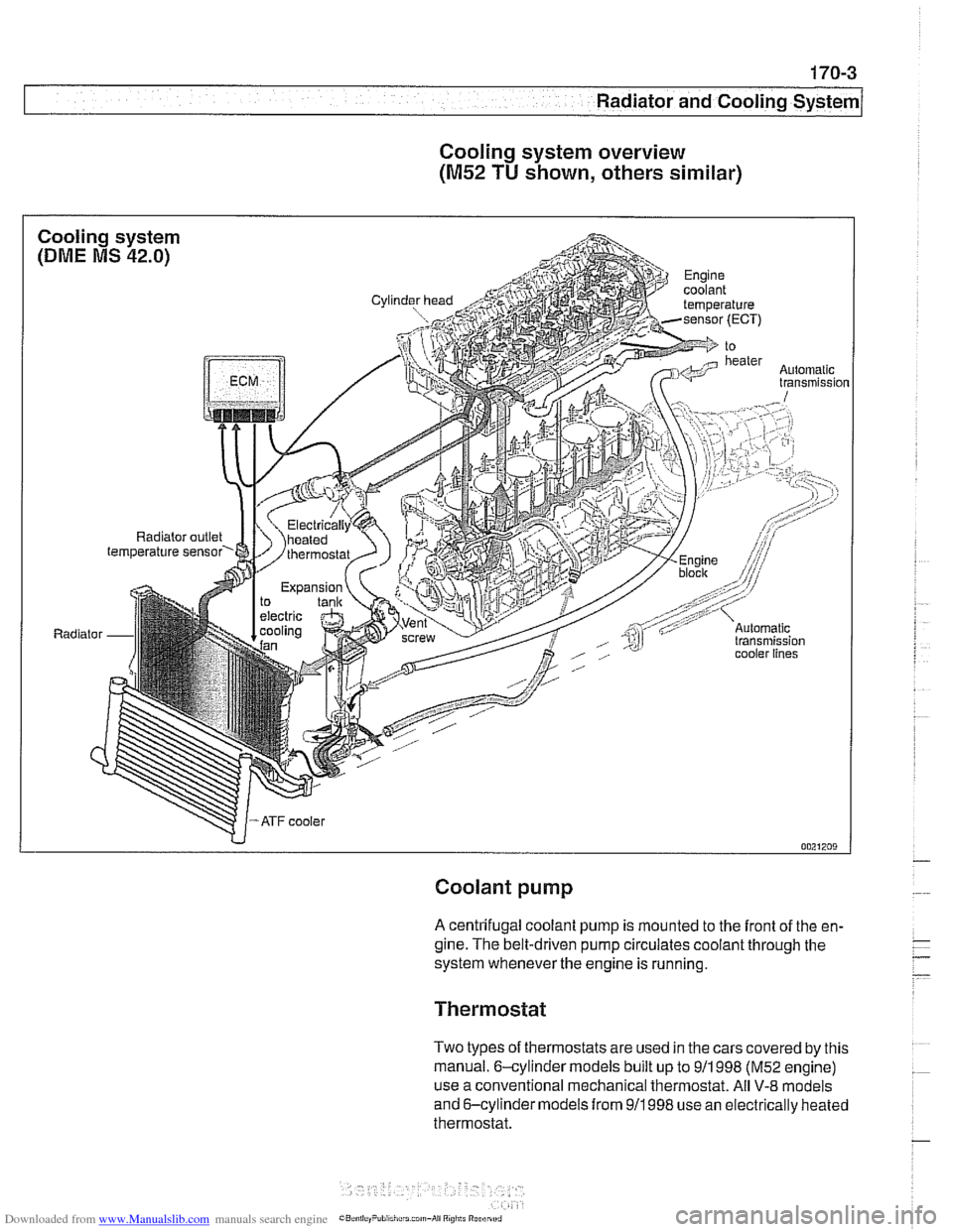
Cooling system overview
(M52 TU shown, others similar)
Coolant pump
A centrifugal coolant pump is mounted to the front of the en-
gine. The belt-driven pump circulates coolant through the
system whenever the engine is running.
Thermostat
Two types of thermostats are used in the cars covered by this
manual. 6-cylinder models built up to
911 998 (M52 engine)
use a conventional mechanical thermostat. All
V-8 models
and 6-cylinder models from
911998 use an electrically heated
thermostat.