Cylinder BMW 540i 1999 E39 Workshop Manual
[x] Cancel search | Manufacturer: BMW, Model Year: 1999, Model line: 540i, Model: BMW 540i 1999 E39Pages: 1002
Page 518 of 1002
Downloaded from www.Manualslib.com manuals search engine
.. - --
Radiator and Cooling System
Tightening torques
Coolant pump to timing chain 10
Nm (89 in-lb)
cover
Coolant pump
pulley to coolant
pump
10 Nm (89 in-lb
Engine
blocic drain plug to block 25 Nm (18 ft-lb)
Radiator drain plug to radiator
2-3Nm(18-27in-lb)
Thermostat cover to coolant
pump assembly 10 Nm (89 in-lb)
Radiator, removing and installing
Removal of the radiator is similar for V-8 and 6-cylinder mod-
els.
- Raise front of car and support safely.
WARNING -
Make sure the car is stable and well supported at aN times.
Use a professional automotive liff
orjaclc stands designed for
- Remove splash shield from under engine.
- Drain radiator and engine block. See Coolant, draining and
filling
(V-8 models).
WARNING -
Allow cooling system to cool before opening or draining sys-
tem.
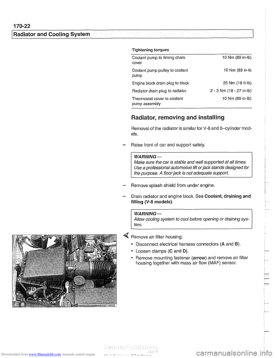
< Remove air filter housing:
Disconnect electrical harness connectors
(A and B).
Loosen clamps (C and D).
Remove mounting fastener (arrow) and remove air filter
housing together with mass air flow
(MAF) sensor.
Page 520 of 1002
Downloaded from www.Manualslib.com manuals search engine
--
Radiator and Cooling System 1
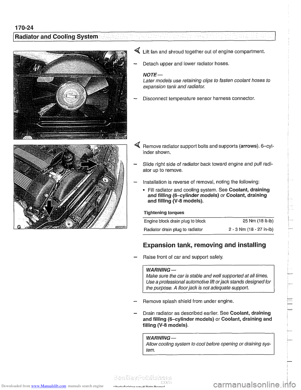
4 Lift fan and shroud together out of engine compartment.
- Detach upper and lower radiator hoses.
NOTE -
Later models use retaining clips to fasten coolant hoses to
expansion tank and radiator.
- Disconnect temperature sensor harness connector.
4 Remove radiator support bolts and supports (arrows). 6-cyl-
inder shown.
- Slide right side of radiator back toward engine and pull radi-
ator up to remove.
- Installation is reverse of removal, noting the following:
Fill radiator and cooling system. See Coolant, draining
and filling (6-cylinder models) or Coolant, draining
and filling (V-8 models).
Tightening torques
Engine block drain
plug to block 25 Nm (18 it-lb)
Radiator drain plug
to radiator 2 - 3 Nm (18 - 27 in-ib)
Expansion tank, removing and installing
- Raise front of car and support safely.
WARNING -
Make sure the car is stable and well supported at all times.
Use a professional automotive
/iff orjacltstands designed for
the purpose. A
floorjacl~ is not adequate support.
- Remove splash shield from under engine.
- Drain radiator as described earlier. See Coolant, draining
and filling (6-cylinder models) or Coolant, draining and
filling
(V-8 models).
I WARNING-
Allow cooling system to cool before opening or draining sys-
I tem.
Page 521 of 1002
![BMW 540i 1999 E39 Workshop Manual Downloaded from www.Manualslib.com manuals search engine
170-25
Radiator and Cooling system]
< Disconnect expansion tank:
Remove expansion tank bleed screw and support clip
(A)
Loosen hose c](/img/1/2822/w960_2822-520.png "BMW 540i 1999 E39 Workshop Manual Downloaded from www.Manualslib.com manuals search engine
170-25
Radiator and Cooling system]
< Disconnect expansion tank:
Remove expansion tank bleed screw and support clip
(A)
Loosen hose c")
Downloaded from www.Manualslib.com manuals search engine
170-25
Radiator and Cooling system]
< Disconnect expansion tank:
Remove expansion tank bleed screw and support clip
(A)
Loosen hose clamp (6) and disconnect coolant hose from
expansion tank.
Disconnect harness connector from coolant level sensor
(C).
Push top of expansion tank toward engine and disconnect
bleed hose.
Lift expansion
tank to free it from lower mounts, then lift
straight up to remove.
- Installation is reverse of removal, noting the following:
Fill radiator and cooling system as described earlier. See
Coolant, draining and filling (6-cylinder models) or
Coolant, draining and filling
(V-8 models).
Page 525 of 1002
Downloaded from www.Manualslib.com manuals search engine
... .
Exhaust System
- With exhaust system fully cold, raise and support car for ac-
cess to exhaust system.
WARNING -
Do not worlc under a lifted car unless it is solidly supported on
jack stands designed for that purpose. Never work under a
car that is supported solely by a
jack.
- Disconnect oxygen sensor connector(s).
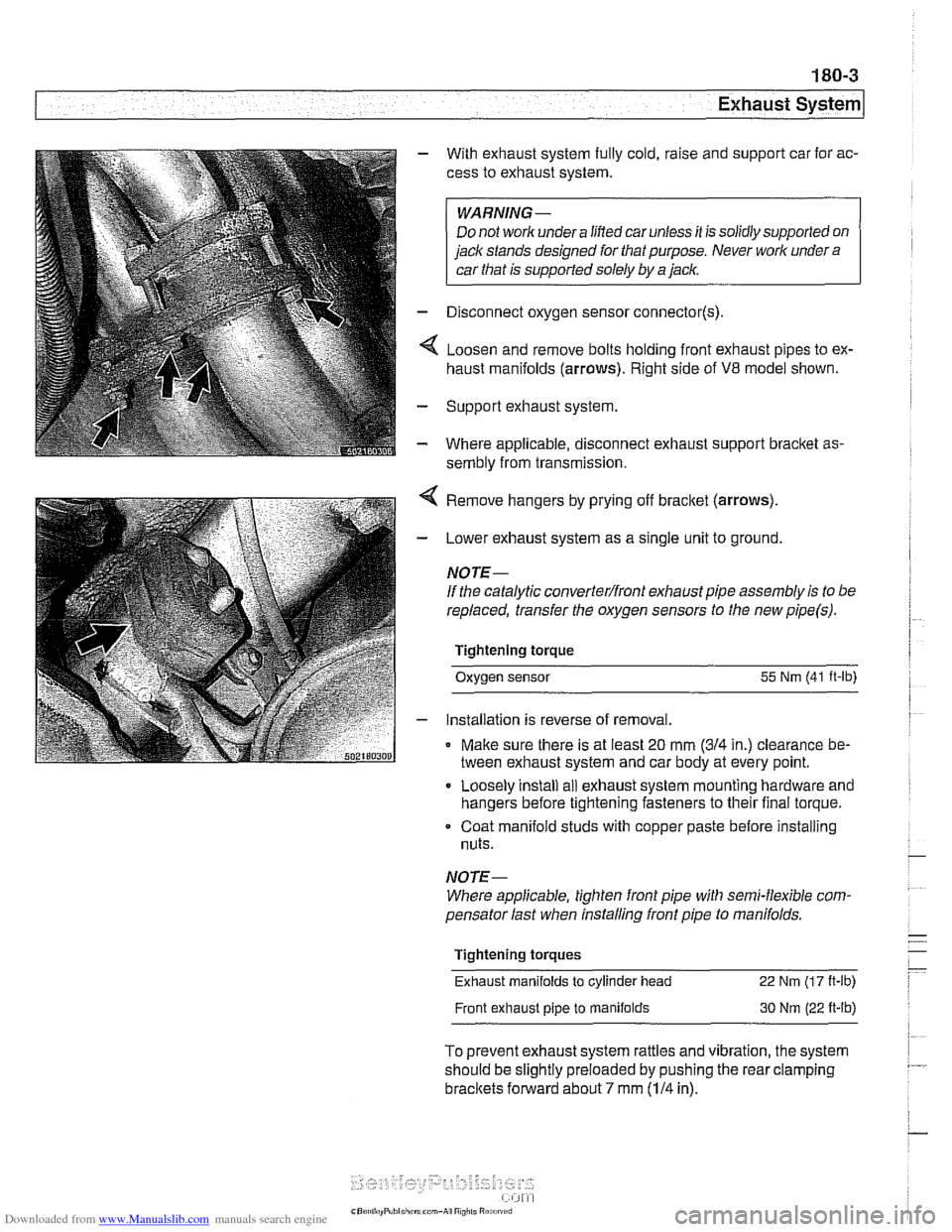
4 Loosen and remove bolts holding front exhaust pipes to ex-
haust manifolds (arrows). Right side of
V8 model shown.
- Support exhaust system
- Where applicable, disconnect exhaust support bracket as-
sembly from transmission.
< Remove hangers by prying off bracket (arrows).
- Lower exhaust system as a single unit to ground.
NOTE-
If the catalytic converterlfront exhaust pipe assembly is to be
replaced, transfer the oxygen sensors to the new
pipe(s).
Tightening torque
Oxygen sensor
55 Nm (41 ft-lb)
- installation is reverse of removal.
* Make sure there is at least 20 mm (314 in.) clearance be-
tween exhaust system and car body at every point.
Loosely install
ail exhaust system mounting hardware and
hangers before tightening fasteners to their final torque.
Coat manifold studs with copper paste before installing
nuts.
NOTE-
Where applicable, tighten front pipe with semi-flexible com-
pensator last when installing front pipe to
manifolds.
Tightening torques
Exhaust manifolds
to cylinder head 22 Nm (1 7 It-lb)
Front exhaust pipe to manifolds 30 Nm (22 ft-lb)
To prevent exhaust system rattles and vibration, the system
should be slightly preloaded by pushing the rear clamping
brackets forward about 7 mm (114 in).
Page 527 of 1002
Downloaded from www.Manualslib.com manuals search engine
Exhaust system1
Exhaust manifold removal procedures are organized accord-
ing to engine code. If necessary, see
100 Engine-General
for engine code and application information.
Exhaust manifolds, removing and installing
(M52 engine)
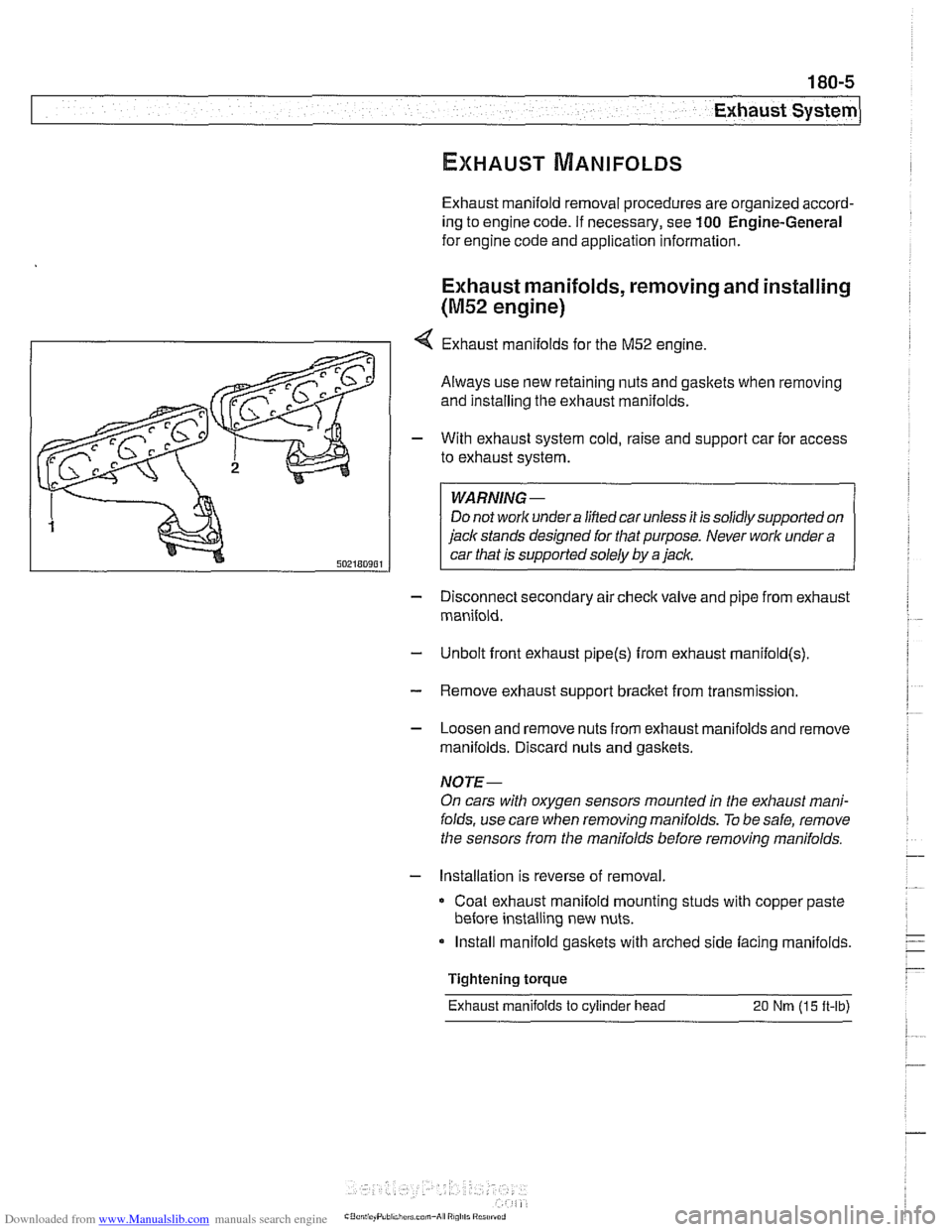
4 Exhaust manifolds for the M52 engine.
Always use new retaining nuts and gaskets when removing
and installing the exhaust manifolds.
- With exhaust system cold, raise and support car for access
to exhaust system.
WARNING -
Do not work under a lined car unless it is solidly supported on
jack stands designed for that purpose. Never work under a
car that is supported solely by a jack.
- Disconnect secondary air check valve and pipe from exhaust
manifold.
- Unbolt front exhaust pipe@) from exhaust rnanifold(s)
- Remove exhaust support bracket from transmission.
- Loosen and remove nuts from exhaust manifolds and remove
manifolds. Discard nuts and gaskets.
NOTE-
On cars with oxygen sensors mounted in the exhaust mani-
folds, use care when removing manifolds.
To be safe, remove
the sensors from the manifolds before removing manifolds.
- Installation is reverse of removal
Coat exhaust manifold mounting studs with copper paste
before installing new nuts.
Install manifold gaskets with arched side facing manifolds.
Tightening torque
Exhaust manifolds
to cylinder head 20 Nm (15 ft-lb)
Page 528 of 1002
Downloaded from www.Manualslib.com manuals search engine
180-6
Exhaust System
Exhaust manifolds, removing and installing
(M52 TU and M54 engines)
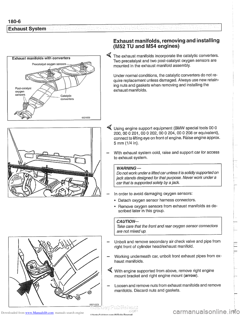
I Exhaust manifolds with converters I 4 The exhaust manifolds incorporate the catalytic converters.
Two precatalyst and two post-catalyst oxygen sensors are
mounted in the exhaust manifold assembly.
Under normal conditions, the catalytic converters do not re-
quire replacement unless damaged. Always use new retain-
ing nuts and gaskets when removing and installing the
exhaust manifolds.
I\
1 4 Using engine support equipment (BMW special tools 00 0
200. 00 0 201. 00 0 202.00 0 204.00 0 208 or equivalent).
connect to
lifting eye on front of engine. Rhise engine approx.
/I 1
5 mm (IH in).
With exhaust system cold, raise and support car for access
to exhaust system.
WARNING-
Do not worlc undera liftedcar unless it is solidly supported on
jack stands designed for that purpose. Never worlc under
a
car that is supported solely by a jaclc.
in order to avoid damaging oxygen sensors:
- Detach oxygen sensor harness connectors,
Remove oxygen sensors from exhaust manifolds as de-
scribed later in this group.
Unbolt and remove secondary air
checkvalve and pipe from
right front of cylinder headlexhaust manifold.
Working underneath car, unbolt front exhaust pipes from ex.
haust manifolds.
With engine supported from above, remove right engine
mount
bracket and right engine mount (arrow).
Loosen and remove nuts from exhaust manifolds and remove
manifolds. Discard nuts and gaskets.
CA UTIOG
Take care tliat the front and rear oxygen sensor connectors
are not mixed up.
-
Page 529 of 1002
Downloaded from www.Manualslib.com manuals search engine
1 Exhaust ~vsteml
NOTE-
The front exhaust manifold must be removed before the rear
manifold.
- Installation is reverse of removal.
Coat exhaust mounting studs with CRC or equivalent cop-
per paste.
Use new gasltets and self-locking nuts.
Tightening torques Exhaust manifold to cylinder head 20 Nm
(15 ft-lb)
Front exhaust pipe to manifold 30 Nm
(22 ft-lb)
Oxygen sensor to manifold 50
Nrn (37 ft-lb)
Exhaust manifolds, removing and installing
(M62 engine)
Always use new retaining nuts and gasltets when removing
and installing the exhaust manifolds.
NOTE-
Access to manifolds is extremely limited. If removing exhaust
manifolds as part of additional engine worlc (such as cylinder
head removal), it may be easier to first remove engine.
- With exhaust system cold, raise and support car for access
to exhaust system.
WARNING -
Do not work undera lifted car unless it is solidly supported on
jaclt stands designed for the purpose. Never worlc undera car
that is supportedsolely
by a jack.
- Remove exhaust system. See Exhaust system, removing
and installing.
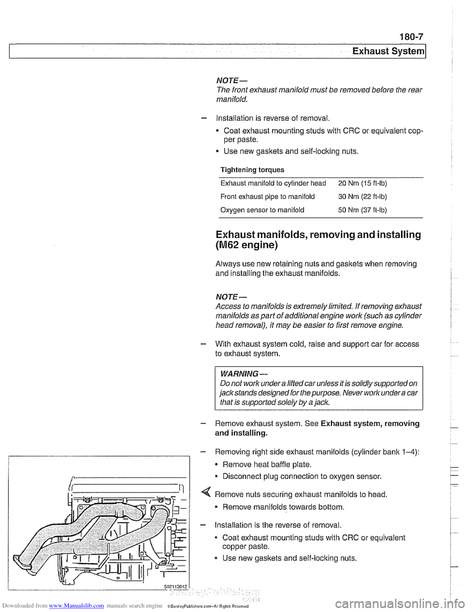
- Removing right side exhaust manifolds (cylinder bank 1-4):
Remove heat baffle plate.
Disconnect plug connection to oxygen sensor.
securing exhaust manifolds to head.
Remove manifolds towards bottom.
- Installation is the reverse of removal.
Coat exhaust mounting studs with CRC or equivalent
copper paste.
Use new gasltets and self-loclting nuts.
Page 530 of 1002
Downloaded from www.Manualslib.com manuals search engine
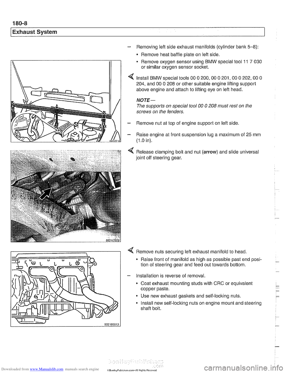
- Removing left side exhaust manifolds (cylinder bank 5-8):
- Remove heat baffle plate on left side.
Remove oxygen sensor using
BMW special tool 11 7 030
or similar oxygen sensor socket.
Install
BMW special tools 00 0 200,OO 0 201,OO 0 202,OO 0
204, and 00 0 208 or other suitable engine lifting support
above engine and attach to lifting eye on left head.
NOTE-
The supports on special tool 00 0 208 must rest on the
screws on the fenders.
- Remove nut at top of engine support on left side
- Raise engine at front suspension lug a maximum of 25 mm
(I
.O in).
Release clamping bolt and nut
(arrow) and slide universal
joint off steering gear.
4 Remove nuts securing left exhaust manifold to head,
Raise front of manifold as high as possible past end posi-
tion of steering gear and feed out towards bottom.
- Installation is reverse of removal.
Coat exhaust mounting studs with CRC or equivalent
copper paste.
Use new exhaust gaskets and self-locking nuts.
Install new self-locking nuts on engine mount and steering
shaft bolt.
Page 533 of 1002
Downloaded from www.Manualslib.com manuals search engine
Exhaust System
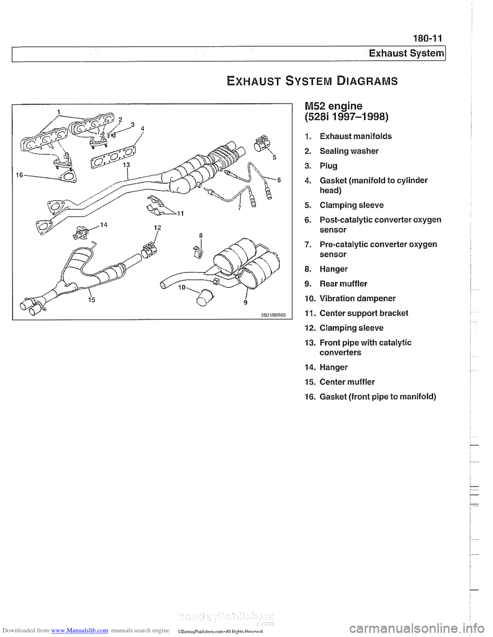
M52 engine
(5281 1997-1 998)
1. Exhaust manifolds
2. Sealing washer
3. Plug
4. Gasket (manifold to cylinder
head)
5. Clamping sleeve
6. Post-catalytic converter oxygen sensor
7. Pre-catalytic converter oxygen
sensor
8. Hanger
9. Rear muffler
10. Vibration dampener
11. Center support bracket
12. Clamping sleeve
13. Front pipe with catalytic
converters
14. Hanger
15. Center muffler
16. Gasket (front pipe to manifold)
Page 543 of 1002
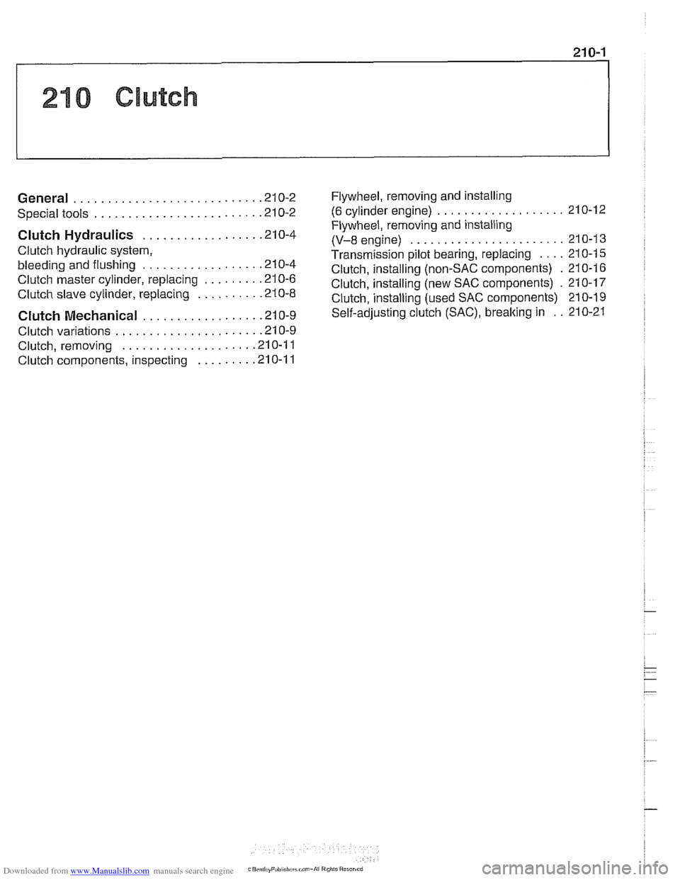
Downloaded from www.Manualslib.com manuals search engine
210 Clutch
........................... General .21 0.2
........................ Special tools .21 0.2
Clutch Hydraulics ................. .21 0.4
Clutch hydraulic system.
bleeding and flushing
................. .21 0.4
Clutch master cylinder. replacing
........ .21 0.6
Clutch slave cylinder. replacing ......... .21 0.8 Flywheel. removing
and installing
................... (6 cylinder engine) 210-12
Flywheel. removing and installing
(V-8 engine) ....................... 21 0-1 3
Transmission pilot bearing. replacing .... 210-1 5
Clutch. installing (non-SAC components) . 210-1 6
Clutch. installing (new SAC components)
. 21 0-17
Clutch.
install in^ (used SAC components) 210-19
Clutch Mechanical ................. .21 0.9 self-adjusting crutch (SAC). breaking in : . 210-21
..................... Clutch variations .21 0.9
................... Clutch. removing .21 0.1 1
Clutch components. inspecting
........ .21 0.1 1