torque BMW 540i 2000 E39 Workshop Manual
[x] Cancel search | Manufacturer: BMW, Model Year: 2000, Model line: 540i, Model: BMW 540i 2000 E39Pages: 1002
Page 548 of 1002
Downloaded from www.Manualslib.com manuals search engine
21 0-6
1 Clutch
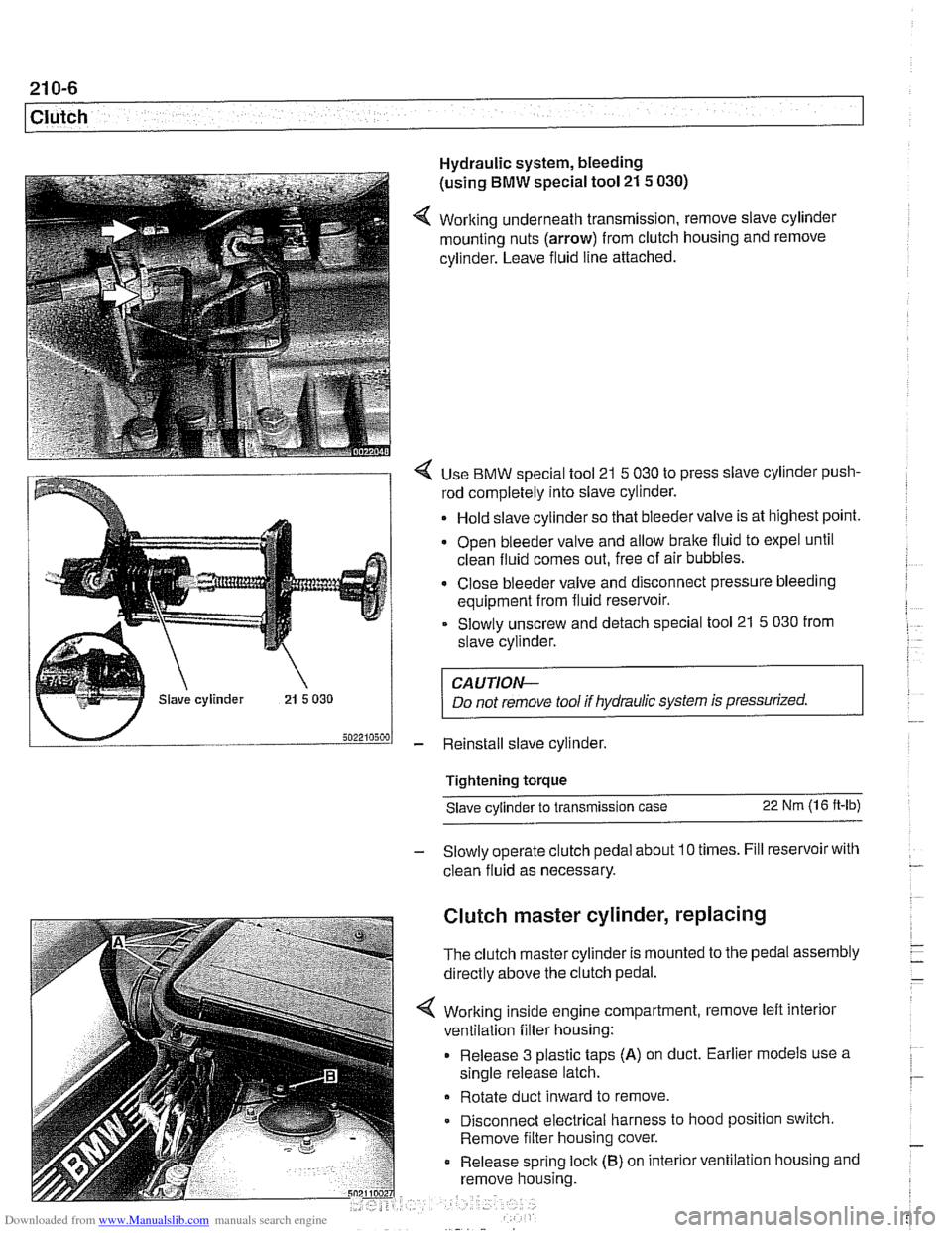
Hydraulic system, bleeding
(using
BMW special tool 21 5 030)
4 Working underneath transmission, remove slave cylinder
mounting nuts (arrow) from clutch housing and remove
cylinder. Leave fluid line attached.
4 Use BMW special tool 21 5 030 to press slave cylinder push-
rod completely into slave cylinder.
Hold slave cylinder so that bleeder valve is at highest point.
Open bleeder valve and allow brake fluid to expel until
clean fluid comes out, free of air bubbles.
* Close bleeder valve and disconnect pressure bleeding
equipment from fluid reservoir.
Slowly unscrew and detach special tool 21
5 030 from
slave cylinder.
CAUTION-
Do not remove tool if hydraulic system is pressurized.
- Reinstall slave cylinder.
Tightening torque Slave cylinder to transmission case
22 Nm (1 6 ft-lb)
- Slowly operate clutch pedal about 10 times. Fill reservoir with
clean fluid as necessary.
Clutch master cylinder, replacing
The clutch master cylinder is mounted to the pedal assembly
directly above the clutch pedal.
Working inside engine compartment, remove left interior
ventilation filter housing:
Release 3 plastic taps
(A) on duct. Earlier models use a
single release latch.
Rotate duct inward to remove
Disconnect electrical harness to hood position switch.
Remove filter housing cover.
Release spring
loclc (B) on interior ventilation housing and
remove housing.
Page 550 of 1002
Downloaded from www.Manualslib.com manuals search engine
21 0-8
Clutch
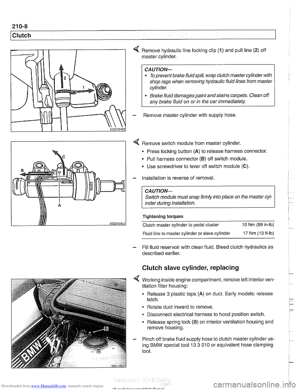
4 Remove hydraulic line locking clip (1) and pull line (2) off
master cylinder.
CAUTION-
. To prevent brake fluidspill, wrap clutch master cylinder with
shop rags when removing hydraulic fluid lines from master
cylinder.
* Brake fluid damages paint andstains carpets. Clean off
any brake fluid on or
in the car immediately.
- Remove master cylinder with supply hose
4 Remove switch module from master cylinder.
Press locking button
(A) to release harness connector.
Pull harness connector
(8) off switch module.
Use screwdriver to lever
off switch module (C).
- Installation is reverse of removal.
CA UTlON-
Switch module must snap firmly into place on the master cyl-
inder during installation.
Tightening torques
Clutch master cylinder to pedal cluster
10 Nm (89 in-lb)
Fluid line
to master cylinder or slave cylinder 17 Nm (13 ft-lb)
- Fill fluid reservoir with clean fluid. Bleed clutch hydraulics as
described earlier.
Clutch slave cylinder, replacing
4 Working inside engine compartment, remove left interiorven-
tilation filter housing:
Release
3 plastic taps (A) on duct. Early models: release
latch.
Rotate duct inward to remove.
Disconnect electrical harness to hood position switch.
Release spring lock (B) on interior ventilation housing and
remove housing.
- Pinch off brake fluid supply hose to clutch master cylinder us-
ing BMW special tool
13 3 01 0 or equivalent hose clamping
tool.
Page 555 of 1002
Downloaded from www.Manualslib.com manuals search engine
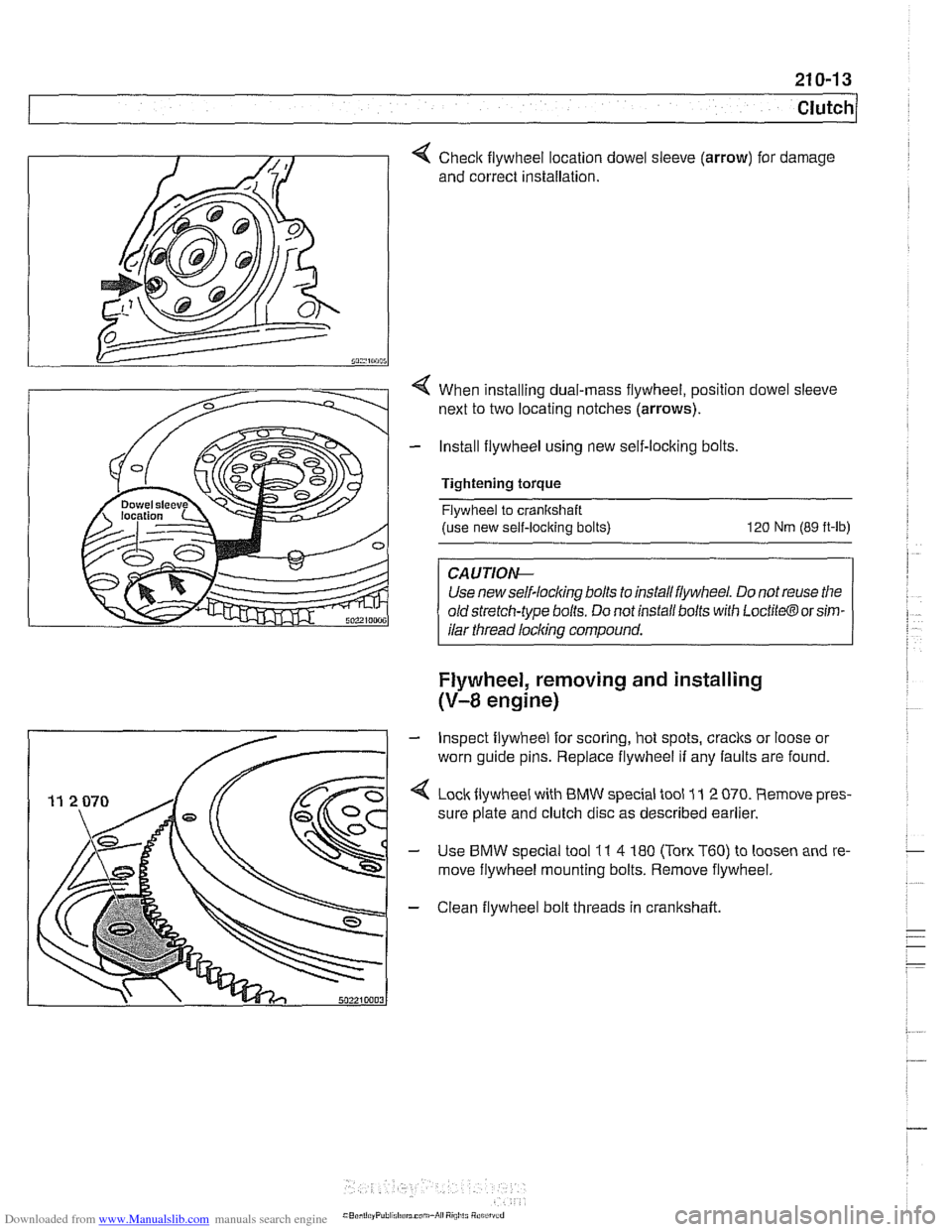
Checlc flywheel location dowel
and correct installation. sleeve (arrow) for
damage
4 When installing dual-mass flywheel, position dowel sleeve
next to two locating notches
(arrows).
- Install flywheel using new self-locking bolts,
Tightening torque Flywheel to cranltshaft
(use new self-locking bolts)
120 Nm (89 ft-lb)
Use new self-lock~ng bolls lo rnslall llylvheel Do not reuse llle
old slrelch-lype bolls Do nor rnsrall bolls wrlh Loct~lo@ or srm-
I ilar thread licking compound. 1
Flywheel, removing and installing
(V-8 engine)
- Inspect flywheel for scoring, hot spots, cracks or loose or
worn guide pins. Replace flywheel if any faults are found.
4 Loclcflywheel with BMW special tool 11 2 070. Remove pres-
sure plate and clutch disc as described earlier.
- Use BMW special tool 11 4 180 (Ton. T60) to loosen and re-
move flywheel mounting bolts. Remove flywheel.
- Clean flywheel bolt threads in crankshaft
Page 556 of 1002
Downloaded from www.Manualslib.com manuals search engine
210-1 4
1 Clutch
Dowel sleeve I
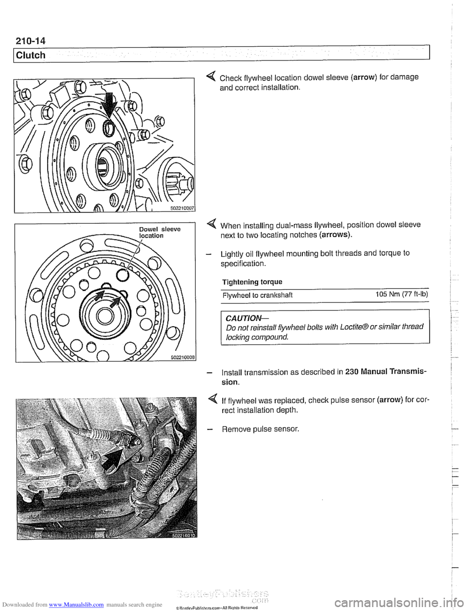
Check flywheel location
and correct installation. dowel sleeve
(arrow)
for . damage
< When installing dual-rnass flywheel, position dowel sleeve
next to two locating notches (arrows).
- Lightly oil flywheel mounting bolt threads and torque to
specification.
Tightening torque
Flywheel to crankshaft 105 Nm (77 ft-lb)
CAUTIOI\C
Do not reinstall flywheel bolls with LoctiteCTJ or similar thread
locl~ing compound.
- Install transm~ssion as descr~bed in 230 Manual Transmis-
sion.
4 If flywheel was replaced, check pulse sensor (arrow) for cor.
rect installation depth.
- Remove pulse sensor.
Page 558 of 1002
Downloaded from www.Manualslib.com manuals search engine
21 0-1 6
Clutch
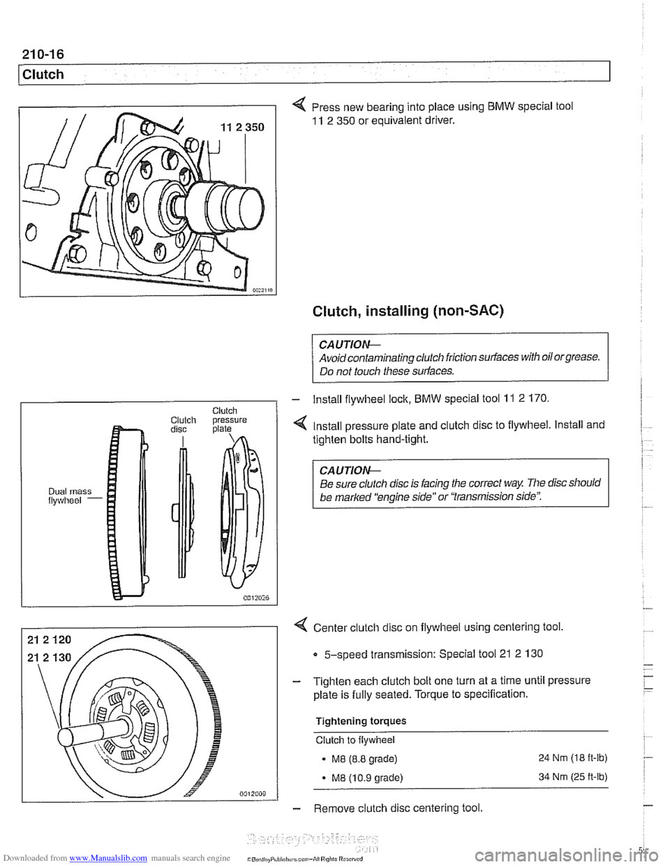
4 Press new bearing into place using BMW special tool
11 2 350 or equivalent driver.
Clutch, installing (non-SAC)
CAUTIOG
Avoidcontaminating clutch friction surfaces with oilorgrease.
Do not touch these surfaces.
4 Center clutch disc on flywheel using centering tool
Clutch Clutch pressure disc plate
Dual mass flywheel -
5-speed transmission: Special tool 21 2 130
- Install flywheel lock, BMW special tool 11 2 170.
4 Install pressure plate and clutch disc to flywheel. Install and
tighten bolts hand-tight.
CAUTIOG
Be sure clutch disc is facing the correct way The disc should
be
marked 'kngine side" or "transmission side':
- Tighten each clutch bolt one turn at a time until pressure
plate is fully seated. Torque to specification.
Tightening torques
Clutch to flywheel
. M8 (8.8 grade) 24 Nrn (18
ft-lb)
- M8 (10.9 grade) 34 Nrn (25 ft-lb)
- Remove clutch disc centering tool.
Page 560 of 1002
Downloaded from www.Manualslib.com manuals search engine
21 0-1 8
Clutch
- lnstall flywheel lock, special tool 11 2 170 (6 cylinder model)
or
11 2 070 (V-8 model).
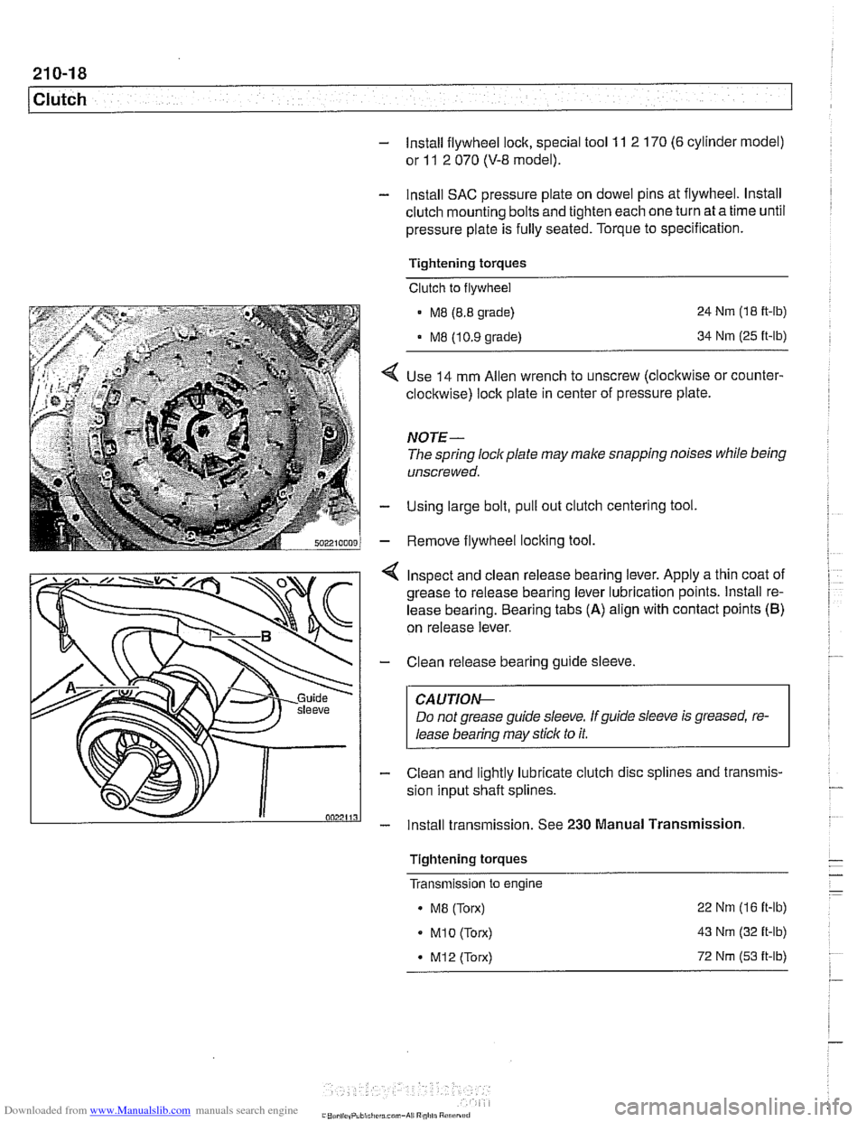
- Install SAC pressure plate on dowel pins at flywheel. lnstall
clutch mounting bolts and tighten each one turn at a time until
pressure plate is fully seated. Torque to specification.
Tightening torques Clutch to flywheel
- M8 (8.8 grade)
MB 110.9 orade)
24 Nm (1 8 it-lb)
34 Nm (25
ft-lb)
Use 14 mm Allen wrench to unscrew (clocltwise or counter-
clockwise) lock plate in center of pressure plate.
NOTE-
The spring lockplate may make snapping noises while being
unscrewed.
Using large bolt, pull out clutch centering tool
Remove flywheel locking tool
4 Inspect and clean release bearing lever. Apply a thin coat of
grease to release bearing lever lubrication points. lnstall re-
lease bearing. Bearing tabs
(A) align with contact points (B)
on release lever.
- Clean release bearing guide sleeve.
CAUTIOG
Do not grease guide sleeve. Ifguide sleeve is greased, re-
lease bearing may stick to it.
- Clean and lightly lubricate clutch disc splines and transmis-
sion input shaft splines.
- lnstall transmission. See 230 Manual Transmission.
Tightening torques
- - - Transmlsslon to engine -
. MB (Torx) 22
Nm (16 it-lb)
MI0 (Torx) 43 Nm (32 it-lb)
* M12 (Torx) 72 Nm (53 it-lb)
.-
Page 562 of 1002
Downloaded from www.Manualslib.com manuals search engine
1 Clutch
- lnstall flywheel lock, special tool 11 2 170 (6 cylinder model)
or
11 2 070 (V-8 model).
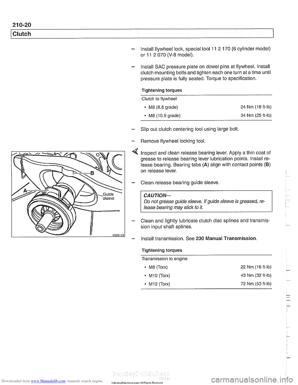
- lnstall SAC pressure plate on dowel pins at flywheel. lnstall
clutch mounting bolts and tighten each one turn at a time until
pressure plate is fully seated. Torque to specification.
Tightening torques
Clutch to flywheel
- M8 (8.8 grade)
M8 (10.9 grade) 24
Nm (18
ft-ib)
34
Nm (25 ft-lb)
- Slip out clutch centering tool using large bolt.
- Remove flywheel locking tool.
Inspect and clean release bearing lever. Apply a thin coat of
grease to release bearing lever lubrication points. lnstall re-
lease bearing. Bearing tabs
(A) align with contact points (B)
on release lever.
- Clean release bearing guide sleeve.
CA U TIOG
Do not grease guide sleeve. If guide sleeve is greased, re-
lease bearing may stick to it.
- Clean and lightly lubricate clutch disc splines and transmis-
sion input shaft splines.
- Install transmission. See 230 Manual Transmission
Tightening torques
Transmission to engine
- ME (Torx)
. M1O (Torx)
. M12 (Torx) 22
Nm (16 ft-lb)
43
Nm (32 ft-lb)
72
Nm (53 it-lb)
Page 563 of 1002
Downloaded from www.Manualslib.com manuals search engine
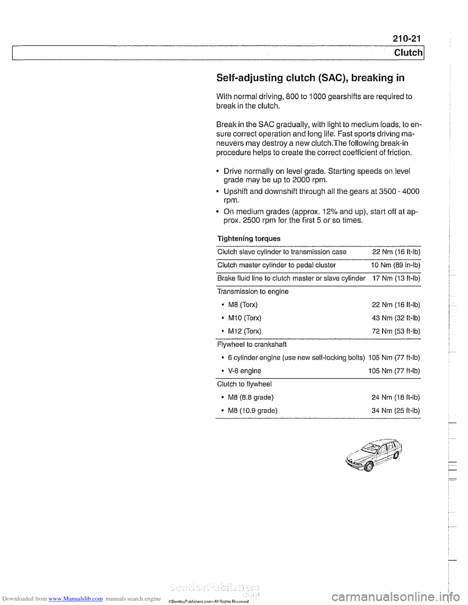
Self-adjusting clutch (SAC), breaking in
With normal driving, 800 to 1000 gearshifts are required to
break in the clutch.
Break in the SAC gradually, with light to medium loads, to en-
sure correct operation and long life. Fast sports driving ma-
neuvers may destroy a new
clutch.The following break-in
procedure helps to create the correct coefficient of friction.
Drive normally on level grade. Starting speeds on level
grade may be up to 2000 rpm.
Upshift and downshift through all the gears at 3500
- 4000
rpm.
On medium grades (approx. 12% and up), start
off at ap-
prox. 2500 rpm for the first 5 or so times.
Tightening torques
Clutch slave cylinder to transmission case 22 Nm (16 It-lb)
Clutch master cylinder to pedal cluster 10 Nm (89 in-lb)
Bralte fluid line to clutch master or slave cylinder 17 Nm (13 ft-lb)
Transmission to engine
M8 (Torx) 22 Nm (16 fl-lb)
. M1O (Torx) 43 Nm (32 ft-lb)
MI2 (Torx) 72 Nm (53 it-lb)
Flywheel to crankshaft
6 cylinder engine (use new self-loclting bolts) 105 Nm (77 ft-lb)
V-8 engine 105 Nm (77 ft-lb)
Clutch to flywheel
M8 (8.8 grade)
M8 (10.9 grade) 24
Nm
(18 ft-lb)
34 Nm (25 ft-lb)
Page 570 of 1002
Downloaded from www.Manualslib.com manuals search engine
230-6
Manual Transmission
Manual transmissions installed in the 5 Series are normally
filled with a "Lifetime" manual transmission fluid
(BMW MTF
LT-I) and do not require periodic fluid changes. Transmis-
sions filled with MTF LT-I lifetime oil are identified with a yel-
low label near the transmission fill plug labeled "Lifetime Oil
MTF-LT-1".
Transmission fluid level, checking
- Drive vehicle for a few miles to warm transmission.
- Raise and safely support vehicle to access transmission
filler plug.
CAUTION-
Make sure the car is stable and well supporfedat all times.
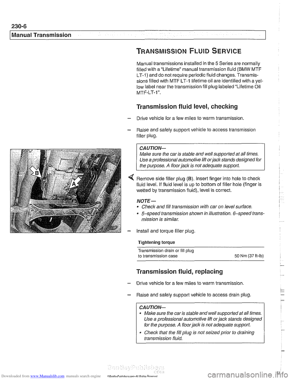
4 Remove side filler plug (B). Insert finger into hole to check
fluid level. If fluid level is up to bottom of filler hole (finger is
wetted by transmission fluid), level is correct.
NOTE-
* Check and fill transmission with car on level surface.
5-speed transmission shown in illustration. 6-speed trans-
mission is similar.
- Install and torque filler plug.
Tightening torque
Transmission drain or fill
plug
to transmission case SO Nm (37 it-lb)
Transmission fluid, replacing
- Drive vehicle for a few miles to warm transmission.
- Raise and safely support vehicle to access drain plug.
CAUTION-
Make sure the car is stable and well supported at all times.
Use a professional automotive lift
orjack stands designed
for the purpose.
A floor jack is not adequate support.
Check that the
fill plug is not seizedprior to draining
transmission fluid.
Page 571 of 1002
Downloaded from www.Manualslib.com manuals search engine
230-7
Manual Transmission
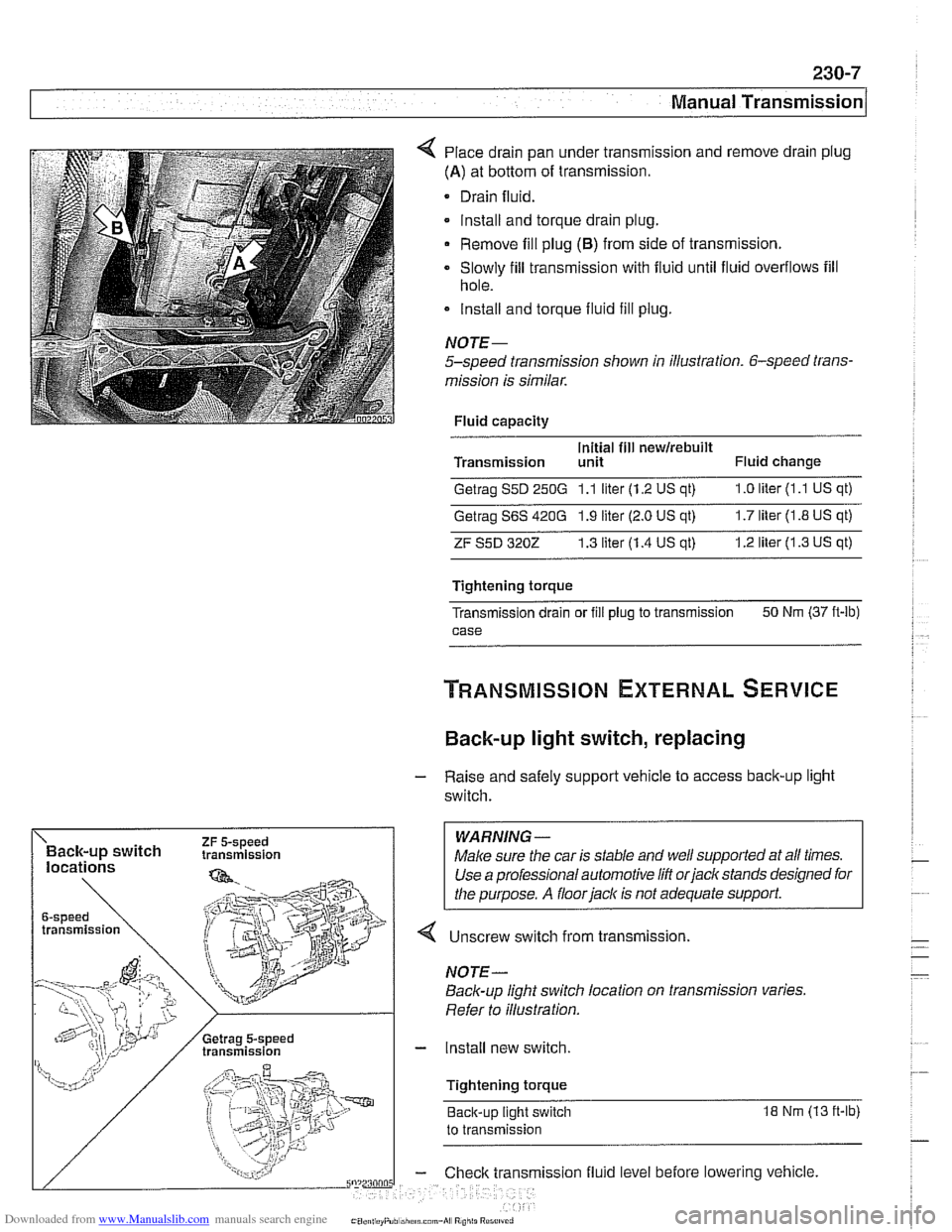
Place drain pan under transmission and remove drain plug
(A) at bottom of transmission.
Drain fluid.
lnstall and torque drain plug.
Remove fill plug
(6) from side of transmission.
Slowly fill transmission with fluid until fluid overflows fill
hole.
lnstall and torque fluid fill
plug.
NOJE-
5-speed transmission shown in illustration. 6-speed trans-
mission is similar.
Fluid capacity
Initial fill
newirebuilt Transmission unit Fluid change
Getrag S5D 250G 1.1 liter (1.2 US qt) 1.0 liter (1 .l US qt)
Getrag S6S 420G 1.9 liter (2.0 US qt) 1.7 liter (1.8 US qt)
ZF S5D 3202 1.3 liter (1.4 US at) 1.2 liter (1.3 US qt)
Tightening torque
Transmission drain or
fill plug to transmission 50
Nm (37 ft-lb)
case
Back-up light switch, replacing
- Raise and safely support vehicle to access back-up light
switch.
WARNING -
4 Unscrew switch from transmission.
Back-up light switch location on transmission varies.
Refer to illustration.
- Install new switch.
Tightening torque Back-up light switch
18 Nm (13 ft-lb)
to transmission
ission fluid level before lowering vehicle.