torque BMW 540i 2000 E39 Workshop Manual
[x] Cancel search | Manufacturer: BMW, Model Year: 2000, Model line: 540i, Model: BMW 540i 2000 E39Pages: 1002
Page 597 of 1002
Downloaded from www.Manualslib.com manuals search engine
240-1 3
Automatic ~ransmissionl
- Blow out oil cooler lines with low-pressure compressed air
and flush cooler with clean ATF twice before reattaching lines
to transmission.
CA UTIOG
Wear safety glasses when worling with compressed air:
@ Do not reuse ATF used for flushing.
- Remainder of installation is reverse of removal, noting the fol-
lowing:
Reinstall driveshafl using new nuts.
Install new sealing washers on transmission cooling line
banjo bolts.
Install new O-rings on transmission cooler lines, where
applicable.
Inspect engine drive plate (flywheel) for cracks or elongat-
ed holes. Replace
if necessary.
Be sure bellhousing alignment dowel sleeves are located
correctly. Replace damaged sleeves.
Checlc to be sure torque converter is seated correctly in
transmission during final installation.
Use
BMW special tool 24 2 300 to align three mounting
tabs on torque converter with indentations on drive plate
(flywheel).
Fill transmission with clean ATF until oil level is even with
fill hole. Then check fluid level as described earlier.
Adjust gearshift mechanism. See
250 Gearshift Linkage.
NOTE-
In order to avoid difficulties in transmission removal at a fu-
ture time, use washers with Torx-head mounting bolts.
Page 598 of 1002
Downloaded from www.Manualslib.com manuals search engine
. .
l~utomatic Transmission
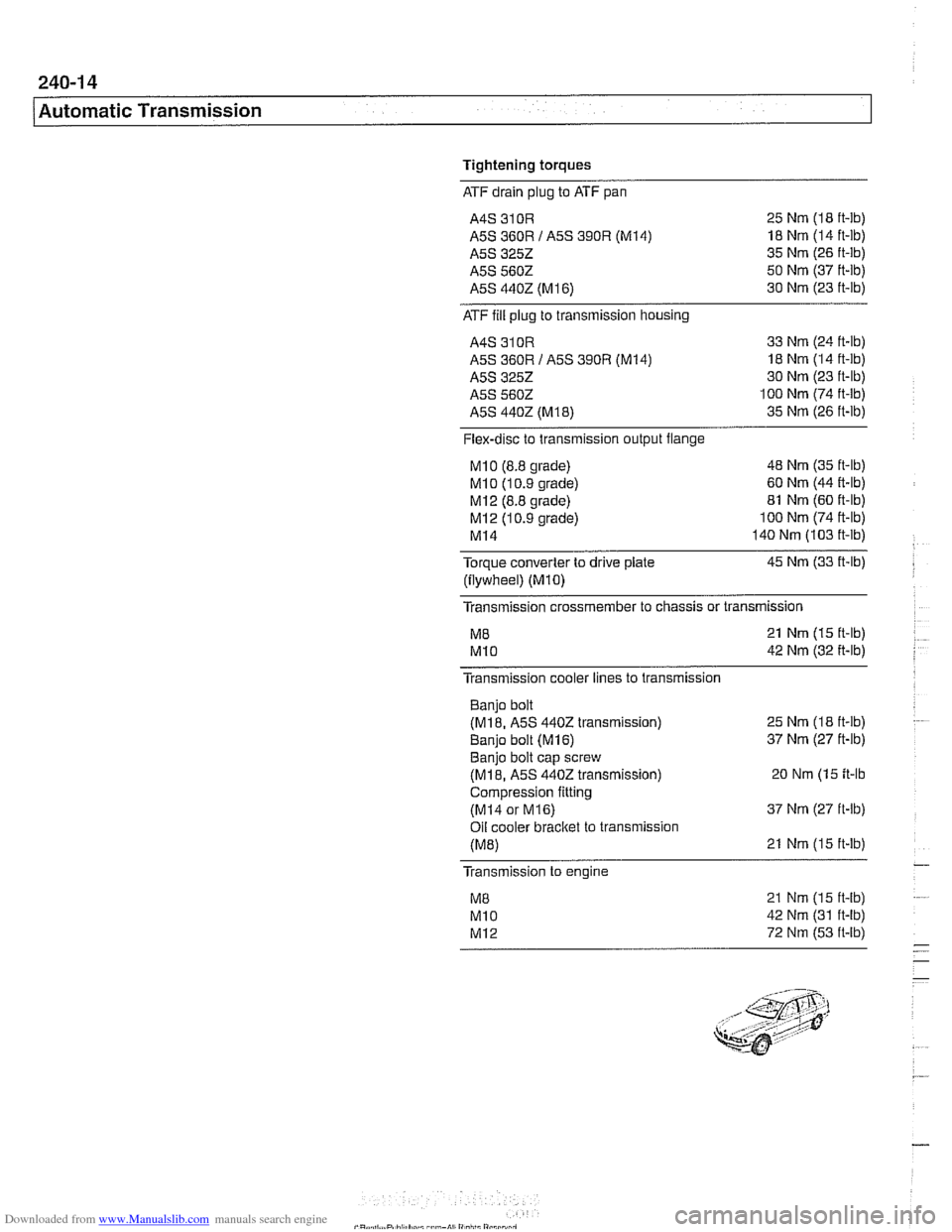
Tightening torques
ATF drain plug to ATF pan
A4S 310R 25 Nm (I8 ft-lb)
A5S 360R I A5S
390R (M14) 18 Nm (14 ft-lb)
A5S 3252 35 Nm (26 ft-lb)
A5S 5602 50 Nm (37 ft-lb)
A5S 4402 (M
16) 30 Nm (23 ft-lb)
ATF fill plug
to transmission housing
A4S 310R 33 Nm (24 ft-lb)
A5S 360R I A5S 390R (M14) 18 Nm (14 ft-lb)
A5S
3252 30 Nm (23 ft-lb)
A5S 5602 100 Nm (74 ft-lb)
A5S
4402 (M18) 35 Nm (26 ft-lb)
Flex-disc to transmission output flange
MI0 (8.8 grade) 48 Nm (35 it-lb)
MI 0 (1 0.9 grade) 60 Nm (44 R-lb)
MI2 (8.8 grade) 81 Nm (60 ft-lb)
MI 2 (1 0.9 grade) 100 Nm (74 ft-lb)
MI4 140 Nm (103 it-lb)
Torque converter to drive plate 45 Nm (33 ft-lb)
(flywheel)
(MIO)
Transmission crossmember to chassis or transmission
M8 21 Nm (15 ft-lb)
MI0 42 Nm (32 it-lb)
Transmission cooler lines to transmission
Banjo bolt
(M18. A5S 4402 transmission)
Banio bolt
(M16)
25 Nm (18 ft-lb)
37 Nm (27 ft-lb) . . Banjo bolt cap screw
(M18, A5S 4402 transmission) 20 Nm (15 it-lb
Compression fitting
(MI4 or M16) 37 Nm (27 ft-lb)
Oil cooler
bracket to transmission
(M8) 21 Nm (15 ft-lb)
Transmission to engine
21 Nm (15 ft-lb)
42 Nm (31 ft-lb)
72 Nm (53 ft-lb)
Page 603 of 1002
Downloaded from www.Manualslib.com manuals search engine
Gearshift Linkage
- Connect selector rod to shift lever. Lift transmission, install
crossmember and tighten crossmember bolts.
Install driveshaft and heat shield. See
260 Driveshaft.
Reinstall exhaust system. See 180 Exhaust System.
. Lower vehicle. Install shift boot. Push shift ltnob on lever.
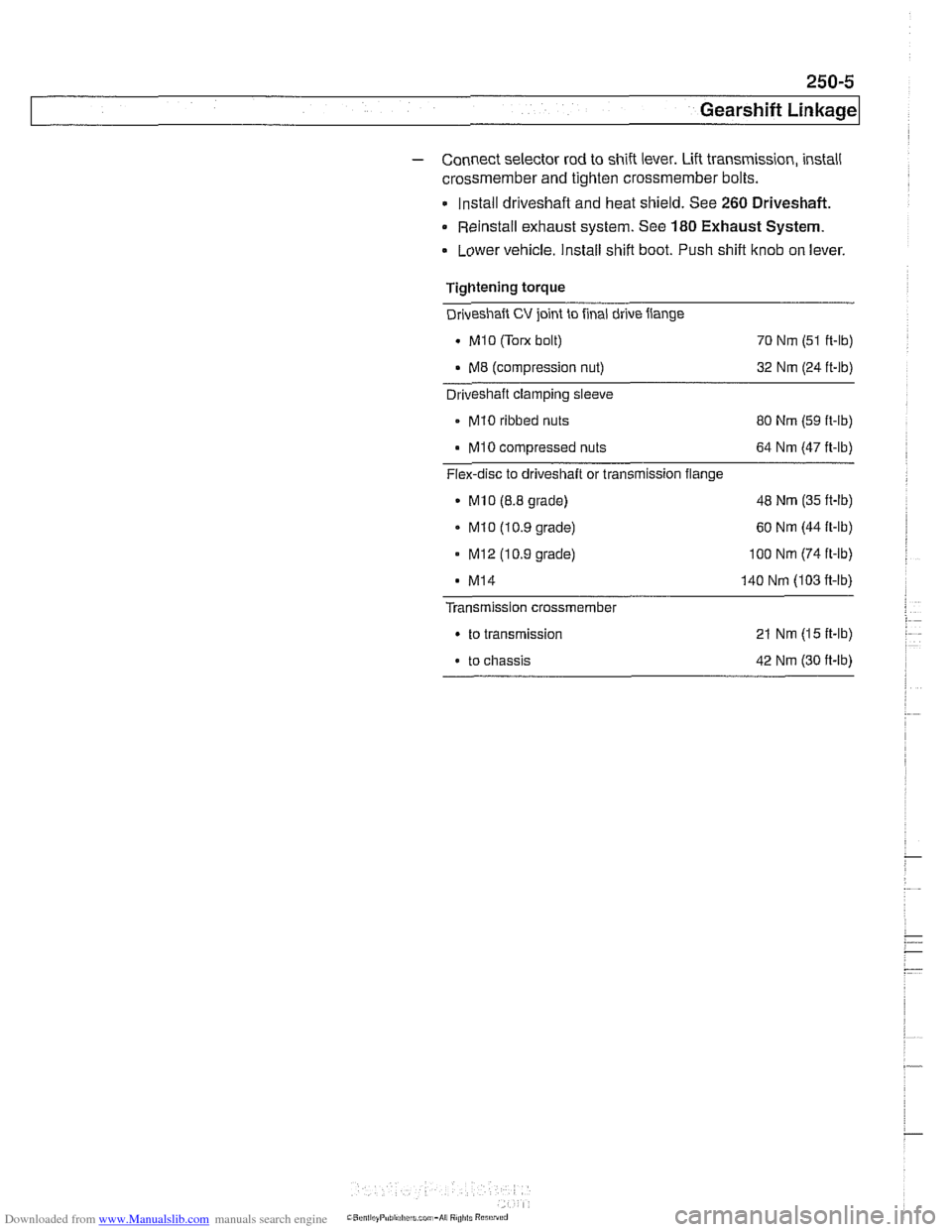
Tightening torque
Driveshaft
CV joint to final drive flange
. MI0 (Tom bolt)
70 Nm (51 ft-lb)
. M8 (compression nut) 32 Nm (24 ft-lb) - Driveshaft clamping sleeve
- MI0 ribbed nuts
80 Nm (59 ft-lb)
MI0 compressed nuts 64 Nm (47 ft-lb)
Flex-disc to driveshaft or transmission flange
MlO (8.8 grade) 48
Nm (35 ft-lb)
. MI0 (10.9 grade) 60
Nm (44 ft-lb)
- MI2 (10.9 grade) 100 Nm (74 ft-ib)
MI4 140 Nm (103 fi-lb)
Transmission crossmember
. to transmission 21 Nm (15 ft-lb)
. to chassis 42 Nm (30 ft-lb)
Page 604 of 1002
Downloaded from www.Manualslib.com manuals search engine
pearshift Linkage
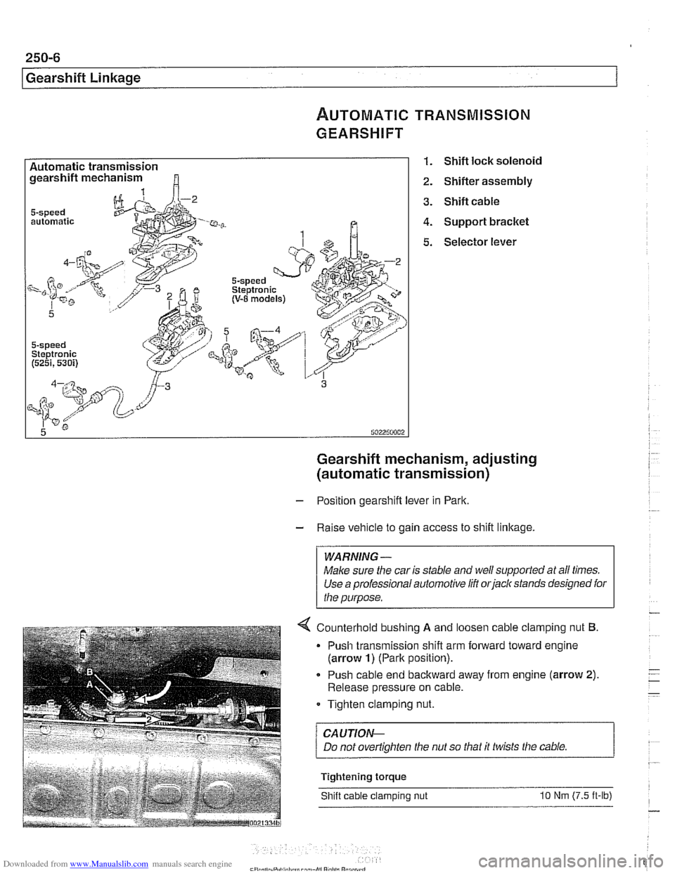
~UTOMATIC TRANSMISSION
GEARSHIFT
Automatic transmission gearshift mechanism
automatic
5-speed Steptronic (5251,530i)
1. Shift lock solenoid
2. Shifter assembly
3. Shift cable
4. Support bracket
5. Selector lever
Gearshift mechanism, adjusting
(automatic transmission)
- Position gearshift lever in Park.
- Raise vehicle to gain access to shift linkage.
WARNING -
Make sure the car is stable and well supported at all times.
Use a professional automotive
lift orjack stands designed for
the purpose.
4 Counterhold bushino A and loosen cable clam~ino nut 6.
Push cable end backward away from engine (arrow 2).
Release pressure on cable.
Tighten clamping nut.
/ CAUTION--
Tightening torque
Shift cable clamping nut
10 Nm (7.5 it-lb)
Page 609 of 1002
Downloaded from www.Manualslib.com manuals search engine
Driveshaft
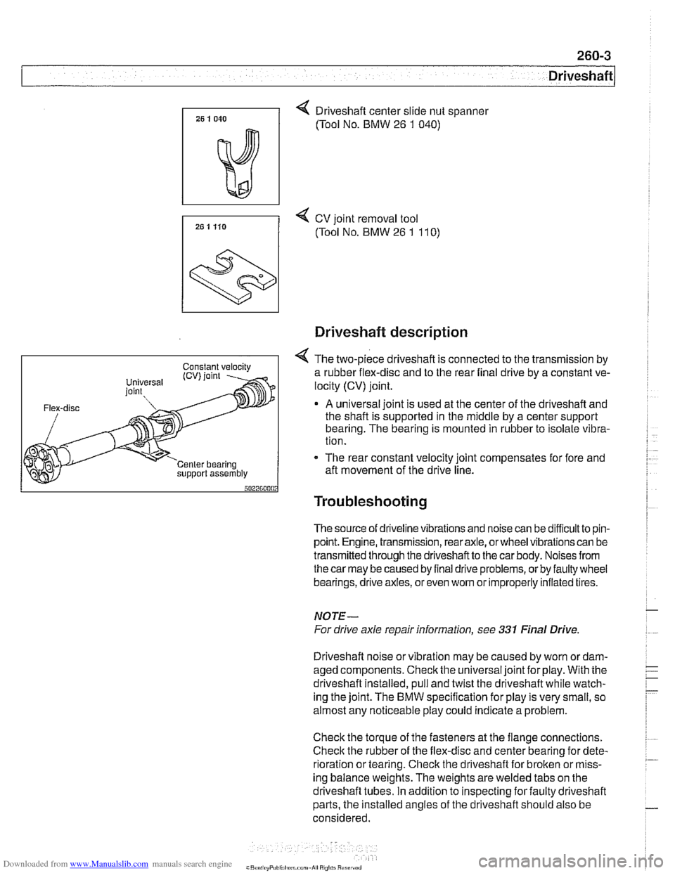
4 Driveshaft center slide nut spanner
(Tool No. BMW
26 1 040)
7, 25 1 Ho 4 cv joint removal tool
(Tool No. BMW 26 1 11 0)
support assembly
Driveshaft description
4 The two-piece driveshaft is connected to the transmission by
a rubber flex-disc and to the rear final drive by a constant ve-
locity (CV) joint.
A universal joint is used at the center of the driveshaft and
the shaft is supported in the middle by a center support
bearing. The bearing is mounted in rubber to isolate vibra-
tion.
- The rear constant velocity joint compensates for fore and
aft movement of the drive line.
Troubleshooting
The source of driveline vibrations and noise can be difficultto pin-
point. Engine, transmission, rear axle, or wheel vibrations can be
transmitted through thedriveshaftto the car body. Noises from
thecar may be caused by final drive problems, or by faulty wheel
bearings, drive axles, or even
wom or improperly inflated tires.
NOTE-
For drive axle repair information, see 331 Final Drive
Driveshaft noise or vibration may be caused by worn
ordam-
aged components. Check the universal joint for play. With the
driveshaft installed, pull and twist the driveshaft while watch-
ing the joint. The
BMW specification for play is very small, so
almost any noticeable play could indicate a problem.
Check the torque of the fasteners at the flange connections.
Check the rubber of the flex-disc and center bearing for dete-
rioration or tearing. Check the driveshaft for broken or miss-
ing balance weights. The weights are welded tabs on the
driveshaft tubes. In addition to inspecting for faulty driveshaft
parts, the installed angles of the driveshaft should also be
considered.
Page 617 of 1002
Downloaded from www.Manualslib.com manuals search engine
Driveshaft
- Road test vehicle to check for noise or vibration
CAUTION-
Do not reuse self-locking nuts. These nuts are designed to
be used only once.
Avoid stressing the flex-disc when torquing the bolts.
Do this by counterholding the bolts and turning the nuts
on the flange side.
Tightening torques
Alunlinum driveshaft to flex-disc
- MI2 (use coated washers)
90 Nm (66 ft-lb)
Driveshaft
CV joint to final drive flange
Mi0 (Tom bolt)
70 Nm (51 ft-lb)
M8 (compression nut) 32 Nm (24 ft-lb)
Flex-disc to transmission flange or driveshaft
MI0 (8.8 grade) 48 Nm (35 ft-lb)
MI 0 (1 0.9 grade) 60 Nm (44 ft-lb)
- Mi2 (8.8 grade)
81 Nm (60 ft-lb)
- MI2 (10.9 grade) I00 Nm (74 ft-lb)
MI4 140 Nm (103 ft-lb)
Transmission
crossmember
to transmission (ME) 21 Nm (15 ft-lb)
. to chassis (M10) 42 Nm (30 ft-lb)
NOTE-
Boltgrade is marked on the bolt head. When replacing bolts,
only use bolts of the same strength and hardness as the orig-
inals installed.
Flex-disc, replacing
- Checlc flex-disc between front section of driveshafl and trans-
mission output flange for craclts, tears, missing pieces, or
distortion. Check for worn bolt hole bores in flange.
- If flex-disc needs replacement, remove driveshafl as de-
scribed earlier.
- Unbolt flex-disc from driveshaft.
NOTE-
Removal andinstallation of the bolts may be made easier by
placing a large hose clamp around the flex-disc, and tighten-
ing the clamp slightly to compress the rubber.
Page 618 of 1002
Downloaded from www.Manualslib.com manuals search engine
260-1 2
1 Driveshaft
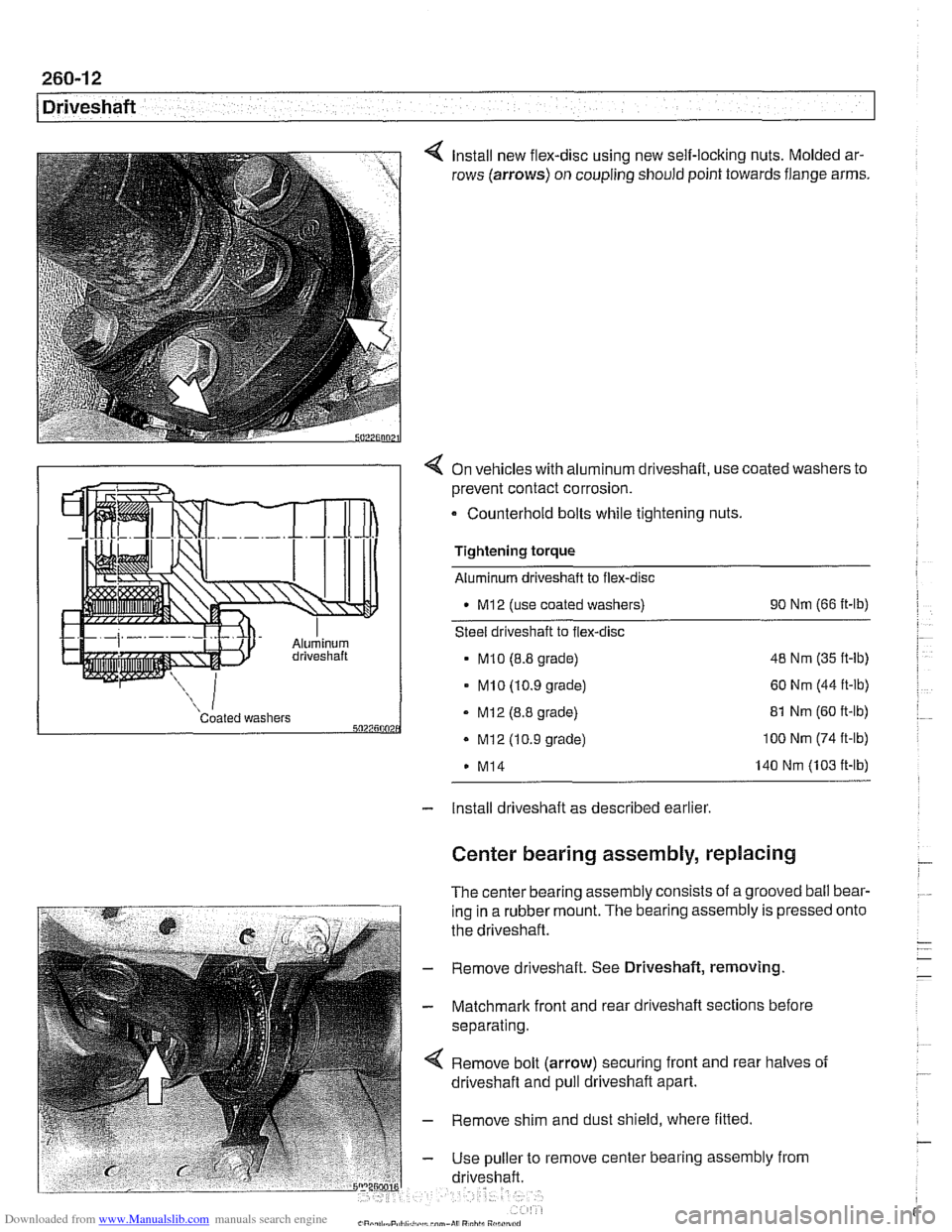
Install new flex-disc using new self-locking nuts. Molded ar-
rows (arrows) on coupling should point towards flange arms.
4 On vehicles with aluminum driveshaft, use coated washers to
prevent contact corrosion.
- Counterhold bolts while tightening nuts.
Tightening torque
Aluminum driveshaft to flex-disc
M12 (use coated washers) 90
Nm (66 ft-lb)
Steel driveshaft to flex-disc
MI0 (8.8 grade) 48
Nm (35 ft-lb)
- MI0 (10.9 grade) 60 Nm (44 ft-lb)
Coated washers - MI2 (8.8 grade) 5027500 . Mi2 (10.9 grade)
M14 81
Nm (60 ft-lb) 100 Nm (74 ft-lb)
140 Nm (103 ft-lb)
- Install driveshaft as described earlier
Center bearing assembly, replacing
The center bearing assembly consists of a grooved ball bear-
ing in a rubber mount. The bearing assembly is pressed
the driveshaft.
- Remove driveshaft. See Driveshaft, removing
- Matchmark front and rear driveshaft sections before
separating.
Remove bolt (arrow) securing front and rear halves of
driveshaft and pull driveshaft apart.
- Remove shim and dust shield, where fitted
- Use puller to remove center bearing assembly from
driveshaft. onto
Page 619 of 1002
Downloaded from www.Manualslib.com manuals search engine
- On installation, drive new center bearing firmly to stop.
Reassemble driveshaft using matchmarks made prior to
disassembly.
- Clean threads and install bolt securing driveshaft halves.
Use thread locking compound
LoctiteO or equivalent.
Tightening torque Driveshaft front half to rear half
(use thread locking compound) 97
Nm (72 fl-lb)
- Install driveshaft as described earlier.
Front centering guide, replacing
The front centering guide centers the driveshafl in relation to
the transmission. The guide is press-fit into a cavity in the
front of the driveshafl and slides onto the transmission output
shaft.
No specifications are given
forwear of the guide, but general-
ly the guide should fit snugly on the transmission output shafl.
NOTE-
Some driveshafts have a dust cap installed on the end of the
driveshaft, over the centering guide. The dust cap may be-
come bent or distorted when the driveshaft is removed or
in-
stalled. Damage to the dust cap should not affect the
centering guide and should not be mistaken for guide wear.
- Remove driveshafl as described earlier
- Pack cavity behind centering guide with heavy grease until
grease is flush with bottom edge of guide.
- Insert 14 mm (approximately 9/16 in.) diameter mandrel or
metal rod into guide. Strike guide with hammer to force cen-
tering guide out.
NOTE-
Tlie mandrel should fit snugly in the centering guide so that
the grease cannot escape around the sides of the mandrel.
- Remove old grease from driveshaft, lubricate new centering
guide with molybdenum disulfide grease
(MolykoteO, Long-
term8 2 or equivalent) and drive it into driveshaft.
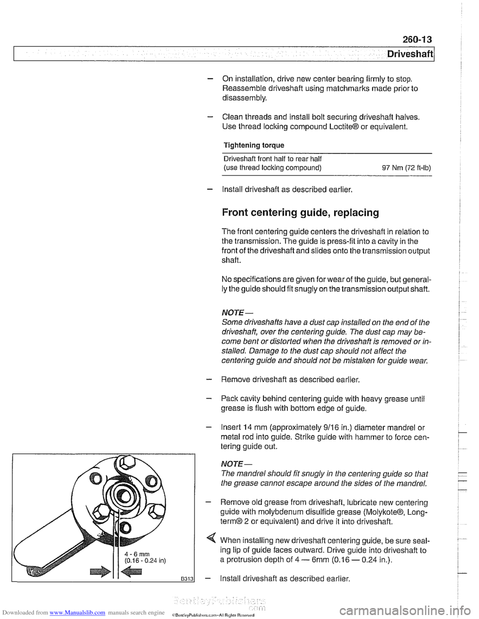
4 When installing new driveshafl centering guide, be sure seal-
ing lip of guide faces outward. Drive guide into driveshaft to
a protrusion depth of
4 - 6mm (0.16 - 0.24 in.).
- Install driveshaft as described earlier.
Page 632 of 1002
Downloaded from www.Manualslib.com manuals search engine
300-1 2
I Sus~ension, Steerincl and Brakes - General
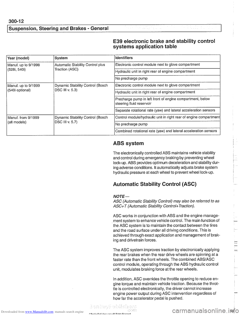
E39 electronic brake and stability control
systems application table
(528i, 54bi) Traction (ASC) I Hydraulic unit in right rear of engine compartment 1
Identifiers
Year (model)
I No precharge pump 1
Manuf. up to 911998 l~utomatic Stability Control plus I Electronic control module next to glove compartment
System
Precharge pump in
lefl front of engine compartment, below
steering fluid reservoir
Separate rotational rate (yaw) and lateral acceleration sensors
I I
Combined rotational rate (yaw) and lateral acceleration sensors
Electronic control
module next to glove compartment
Hydraulic unit in right rear of engine compartment
Manuf. up to 911999
(540i optional)
I I
ABS system
Dynamic Stability Control (Bosch
DSC
Ill v. 5.3)
The electronically controlled
ABS maintains vehicle stability
and control during emergency braking by preventing wheel
lock-up.
ABS provides optimum deceleration and stability dur-
ing adverse conditions. It automatically adjusts brake system
hydraulic pressure at each wheel to prevent wheel lock-up.
Control
moduleihydraulic unit
in right rear of engine compartment
No precharge pump
Manuf. from
911999
(all models)
Automatic Stability Control (ASC)
Dynamic Stability Control (Boscli
DSC Ill v. 5.7)
NOJE-
ASC (Automatic Stability Control) may also be referred to as
ASCiT (Automatic Stability ControkTraction).
ASC works in conjunction with ABS and the engine manage-
ment system to enhance vehicle control. The main function of
the
ASC system is to maintain the contact between the tires
and the road surface under all driving conditions. This is
achieved through exact application and management of brak-
ing and drivetrain forces.
The
ASC system improves traction by electronically applying
the rear brakes when the rear drive wheels are spinning at a
faster rate than the front wheels. The combined
ABSIASC
control module, operating through the ABS hydraulic control
unit, modulates braking force at the rear wheels.
In addition,
ASC overrides the throttle opening to reduce en-
gine torque and maintain vehicle traction. Because the throt-
tle is controlled electronically, the driver cannot increase
engine power output during
ASC intervention regardless of
how far the accelerator pedal is pushed.
Page 634 of 1002
Downloaded from www.Manualslib.com manuals search engine
300-1 4
I Susoension. Steerina and Brakes - General
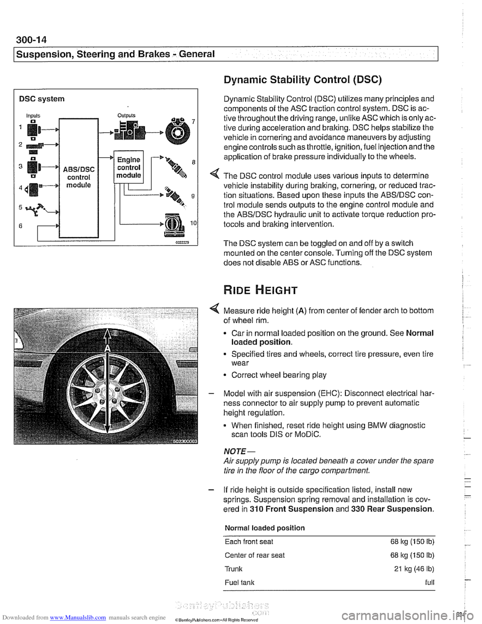
DSC system I
Dynamic Stability Control (DSC)
Dynamic Stability Control (DSC) utilizes many principles and
components of the ASC traction control system. DSC is ac-
tive throughoutthe driving range, unlike ASC which is only ac-
tive during acceleration and braking. DSC helps stabilize the
vehicle in cornering and avoidance maneuvers by adjusting
engine controls such as throttle, ignition, fuel injection and the
application of
brake pressure individually to the wheels.
Inputs
fi- 0
2 4-* .. o
[11-' IJ
411m4
3?-
G
4 The DSC control module uses various inputs to determine
vehicle instability during braking, cornering, or reduced trac-
tion situations. Based upon these inputs the ABSIDSC con-
trol module sends outputs to the engine control module and
the ABSIDSC hydraulic unit to activate torque reduction pro-
tocols and braking intervention.
-
ABSIDSC control module
OUI~YIS
4
The DSC system can be toggled on and off by a switch
mounted on the center console. Turning off the DSC system
does not disable ABS or ASC functions.
+
Measure ride height (A) from center of fender arch to bottom
of wheel rim.
Car in normal loaded position on the ground. See Normal
loaded position.
Engine
control
module
Specified tires and wheels, correct tire pressure, even tire
wear
-'* 9-
.%A
Correct wheel bearing play
T'== ..t, 9 B
-.m
Model with air suspension (EHC): Disconnect electrical har-
ness connector to air supply pump to prevent automatic
height regulation.
When finished, reset ride height using BMW diagnostic
scan tools DIS or
MoDiC.
NOTE-
Airsupply pump is located beneath a cover under the spare
tire in the floor of the cargo compartment.
- If ride height is outside specification listed, install new
springs. Suspension spring removal and installation is cov-
ered in
310 Front Suspension and 330 Rear Suspension.
Normal loaded position
Each front seat 68 kg (150 Ib)
Center of rear seat 68 kg (150 lb)
Trunk 21 kg (46 lb)
Fuel tank full