length BMW 540i 2000 E39 Workshop Manual
[x] Cancel search | Manufacturer: BMW, Model Year: 2000, Model line: 540i, Model: BMW 540i 2000 E39Pages: 1002
Page 26 of 1002
Downloaded from www.Manualslib.com manuals search engine
.-
General
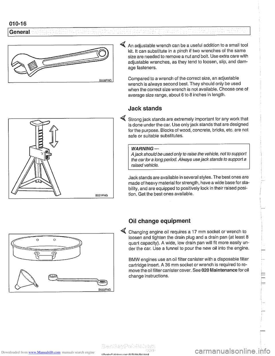
4 An adjustable wrench can be a useful addition to a small tool
kit. It can substitute in a pinch if two wrenches of the same
size are needed to remove a nut and bolt. Use extra care with
adjustable wrenches, as they tend to loosen, slip, and dam-
age fasteners.
Jack stands
v
BOOBFNG
4 Strong jack stands are extremely important for any work that
is done under the car. Use only jack stands that are designed
for the purpose.
Blocks of wood, concrete, bricks, etc. are not
safe or suitable substitutes.
A
jaclc should be used only to raise the vehicle, not to support
the car for a long period. Always use
jack stands to support a
Jackstands are available in several styles. The best ones are
:
made of heavy material for strength, have a wide base for sta-
bility, and are equipped to positively lock in their raised posi-
tion. Get the best ones available.
Compared to
a wrench of the correct size, an adjustable
Oil change equipment
wrench is always second best. They should only be used
when the correct size wrench is not available. Choose one of
average size range, about
6 to 8 inches in length.
4 Changing engine oil requires a 17 mm socket or wrench to
loosen and tighten the drain plug and a drain pan (at least
8
quart capacity). A wide, low drain pan will fit more easily un-
der the car. Use a funnel to pour the new oil into the engine.
BMW engines use an oil filter canister with a disposable filter
cartridge insert. A
36 mm socket or wrench is required to re-
move the oil filtercanistercover. See
020 Maintenance foroil
change instructions.
Page 112 of 1002
Downloaded from www.Manualslib.com manuals search engine
I Cylinder Head Removal and Installation
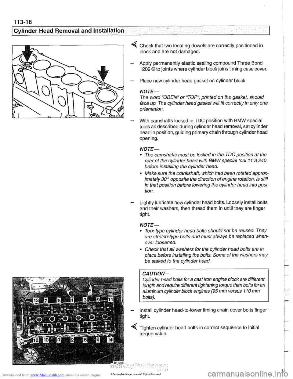
4 Check that two locating dowels are correctly positioned in
block and are not damaged.
- Apply permanently elastic sealing compound Three Bond
1209 8 to joints where cylinder block joins timing case cover.
- Place new cylinder head gasket on cylinder block.
NOTE-
The word "OBEN" or 'TOP': printed on the gasket, should
face up. The cylinder head
gasket will fit correctly in only one
orientation.
- With camshafts locked in TDC oosition with BMW soecial
tools as described during cylinder head removal,
seicylinder
head in position, guiding primary chain through cylinder head
opening.
NOTE-
* The camshafts must be locl(ed in the TDC position at the
rear of the cylinder head with
BMW special tool I1 3 240
before installing the cylinder head.
Make sure the
cranksha% which had been rotated approx-
imately
30" opposite the direction of engine rotation, is still
in that position before lowering the cylinder head into posi-
tion.
- Lightly lubricate new cylinder head bolts. Loosely install bolts
and their washers, then thread them in until they are finger
tight.
NOTE-
. Torx-type cylinder head bolts should not be reused. They
are stretch-type bolts and must always be replaced when-
ever loosened.
Check that all washers for the cylinder head bolts are in
place before installing the bolts. Some of the washers may
be
stalced to the cylinder head.
CAUTIOI\C
Cylinder head bolts for a cast iron engine block are different
length and require different tightening torque than bolts for an
aluminum cylinder bloclc engines
(95 rnm versus 110 rnm
bolts).
- Install cylinder head-to-lower timing chain cover bolts finger
tight.
< Tighten cylinder head bolts in correct sequence to initial
torque value.
Page 134 of 1002
Downloaded from www.Manualslib.com manuals search engine
11 3-40
I Cylinder Head Removal and Installation
Lubricate camshafts, camshaft carriers, bearing caps, hy-
draulic lifters, friction washers, splined shafts and spline hubs
with assembly lubricant before installation.
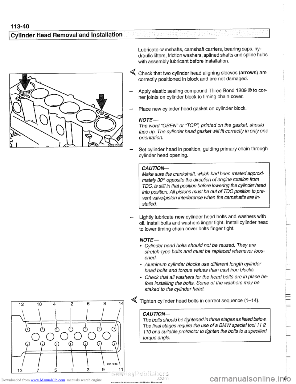
4 Check that two cylinder head aligning sleeves (arrows) are
correctly positioned in block and are not damaged.
- Apply elastic sealing compound Three Bond 1209 8 to cor-
ner joints on cylinder block to timing chain cover.
- Place new cylinder head gasket on cylinder block.
NOTE-
The word "OBEN" or "TOP printed on the gasket, should
face up. The cylinder headgaslet will fit correctly in only one
orientation.
- Set cylinder head in position, guiding primary chain through
cylinder head opening.
CAUJION-
Make sure the crankshaft, which had been rotated approxi-
mately 30" opposite the direction of engine rotation from
TDC, is still in thatposition before lowering the cylinder head
into position. All pistons must be out of TDC position to pre-
vent
valve/piston interference when the camshafts are in-
stalled.
- Lightly lubricate new cylinder head bolts and washers with
oil. Install bolts and washers finger tight. Install cylinder head
to lower timing chain cover bolts finger tight.
NOJE-
Cylinder head bolts should not be reused. They are
stretch-type bolts and must be replaced whenever loos-
ened.
* Aluminum cylinder blocls use different length cylinder
head bolts and torque values than cast iron blocks.
Check that all washers for
Nle head bolts are in place be-
fore installing the bolts. Some of the washers may be
staked to the cylinder head.
I 12 10 4 2 6 8 141 Tighten cylinder head bolts in correct sequence (1-14)
CA U TIOW-
The bolts should be tightened in three stages as listed below
The final stages require the use of a BMW special tool
11 2
110 or a suitable protractor to tighten the bolts to a specified
torque angle.
Page 361 of 1002
Downloaded from www.Manualslib.com manuals search engine
ignition System
Crankshaft speed sensor, replacing (M62 and M62TU
engines)
The crankshaft speed sensor reads a toothed pulse wheel
mounted on the flywheel.
If the Engine Control Module(ECM)
does not receive an impulse signal from the crankshaft speed
sensor during
cranking, the engine will not start. If the OBD II
system misfire detection protocol detects a catalyst damag-
ing fault due to a malfunction in the crankshaft speed sensor
components, the Check Engine light (Malfunction
Indicator
Light or MIL) will be Illuminated.
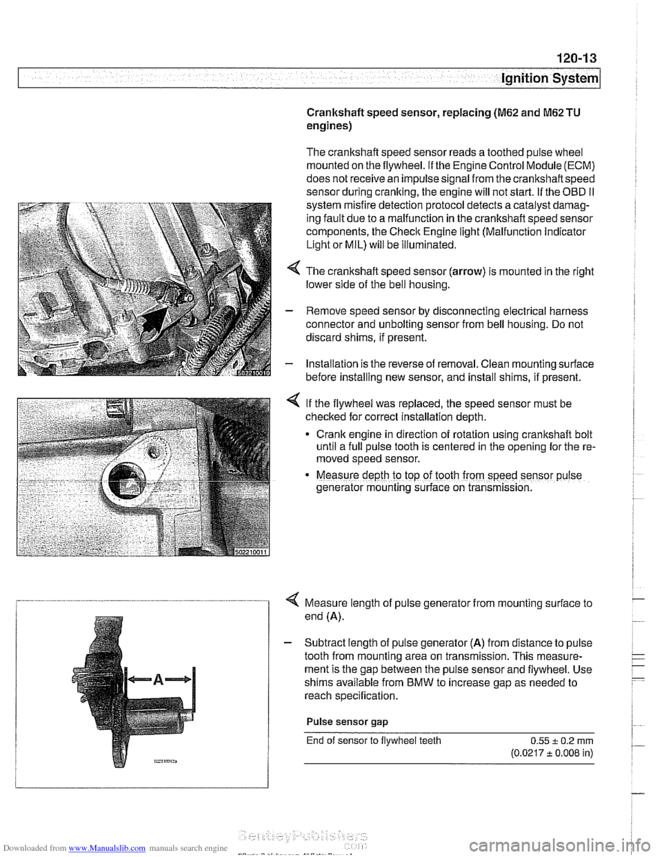
4 The crankshaft speed sensor (arrow) is mounted in the right
lower side of the bell housing.
- Remove speed sensor by disconnecting electrical harness
connector and unbolting sensor from bell housing. Do not
discard shims, if present.
- Installation is the reverse of removal. Clean mounting surface
before installing new sensor, and install shims, if present.
< If the flywheel was replaced, the speed sensor must be
checked for correct installation depth.
* Crank engine in direction of rotation using crankshaft bolt
until a full pulse tooth is centered in the opening for the re-
moved speed sensor.
Measure depth ro top of tooth from speed sensor p~lse
generator mounting s~rface on transmission.
4 Measure length of pulse generator from mounting surface to
end (A).
- Subtract length of pulse generator (A) from distance to pulse
tooth from mounting area on transmission. This measure-
ment is the gap between the pulse sensor and flywheel. Use
shims available from BMW to increase gap as needed to
reach specification.
Pulse sensor
gap
End of sensor to flywheel teeth 0.55 + 0.2 rnrn
(0.0217 t 0.008 in)
Page 375 of 1002
Downloaded from www.Manualslib.com manuals search engine
121-9
Battery, Starter, ~lternatorl
Battery charging
Discharged batteries can be recharged using a batterycharg-
er. Remove the battery from the trunk during charging.
Prolonged charging causes electrolyte evaporation to a level
that can damage the battery. It is best to use a low-current
charger
(6 amperes or less) to prevent battery damage
caused by overheating.
WARNING -
Hydrogen gas given off by the battery during charging is ex-
plosive. Do not smoke.
Keep open flames away from the top
ofthe batte~ and prevent electrical sparks by turning off the
battery charger before connecting or disconnecting it.
Battery electrolyte (sulfuric acid) can damage the car. If
electrolyte is spilled, clean the area with a solution
ofbak-
ing soda and water.
Always allow a frozen battery to thaw before attempting
to recharge it.
Always disconnect both battery cables and remove bat-
tery from vehicle during battery charging. Do not ex-
ceed
16.5 charging voltage at the battery
Battery safety terminal, replacing
If the battery safety terminal has been triggered, investigate
and correct the cause prior to replacement.
- Working in right side of luggage compartment, remove bat-
tery trim panel.
- Disconnect negative (-) battery terminal and cover with
insulator.
- Disconnect positive (+) cable from battery.
- Release positive (+) cable from cable brackets on luggage
compartment wall. Lay new repair cable parallel to positive
cable.
- Mark off length of new cable on old cable. Allow 10 cm
(2.5 in) of slack.
- Saw through old cable.
Do not use bolt cutters or similar tools to cut through cable.
A cable end that has been squashed
flat will not fit into the
Page 517 of 1002
Downloaded from www.Manualslib.com manuals search engine
Radiator and Coolina ~vsteml
- Disconnect thermostat and cooling system temperature sen-
sor plug connectors.
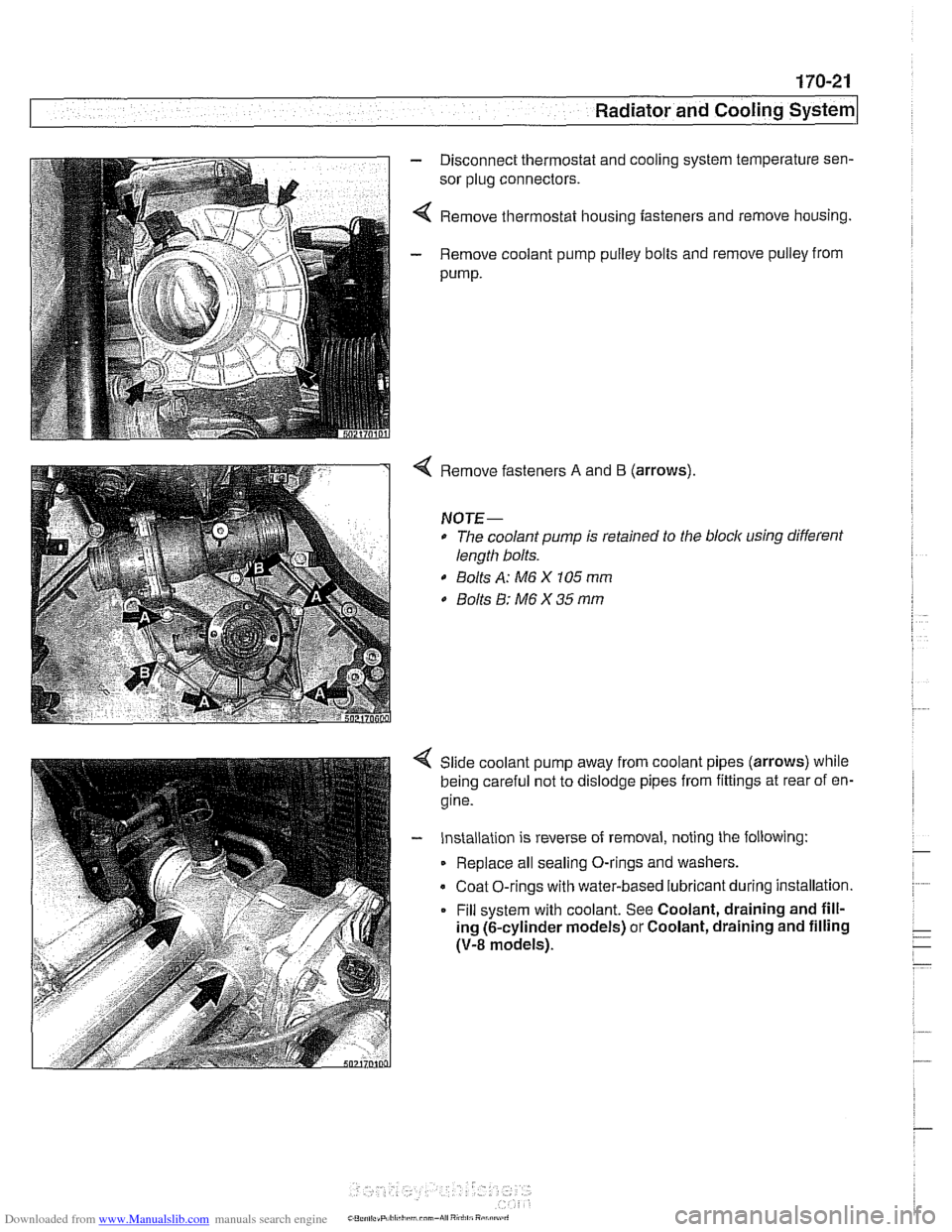
4 Remove thermostat housing fasteners and remove housing.
- Remove coolant pump pulley bolts and remove pulley from
pump.
Remove fasteners A and B (arrows).
NOTE-
* The coolant pump is retained to the block using different
length bolts.
0 Bolts A: M6 X 105 mm
0 Bolts 8: M6 X 35 mm
Slide coolant pump away from coolant pipes (arrows) while
being careful not to dislodge pipes from fittings at rear of en-
gine.
- Installation is reverse of removal, noting the following:
Replace all sealing O-rings and washers.
Coat O-rings with water-based lubricant during installation.
Fill system with coolant. See Coolant, draining and fill-
ing (6-cylinder models) or Coolant, draining and filling
(V-8 models).
Page 526 of 1002
Downloaded from www.Manualslib.com manuals search engine
/Exhaust System Muffler, replacing
BMW offers individual mufflers as replacement parts for the
original one-piece assembly. Replacement of a rear muffler
may be possible with the system installed on the car. Re-
placement of the front or middle muffler should only be done
with the exhaust removed from the car.
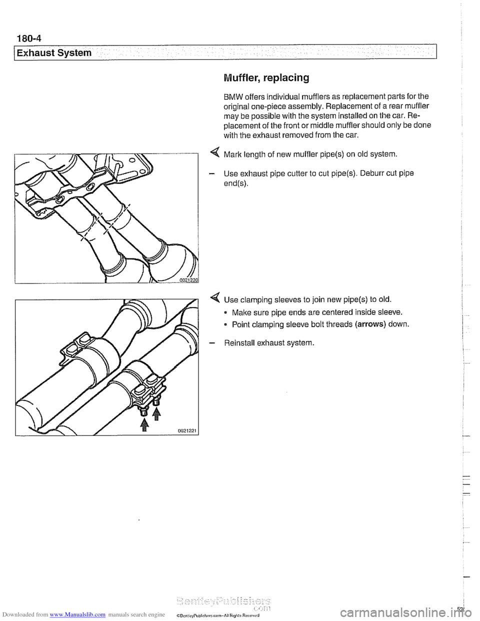
< Mark length of new muffler pipe(s) on old system.
- Use exhaust pipe cutter to cut pipe(s). Deburr cut pipe
end@).
4 Use clamping sleeves to join new pipe(s) to old.
Make sure pipe ends are centered inside sleeve.
Point clamping sleeve bolt threads
(arrows) down.
- Reinstall exhaust system.
Page 557 of 1002
Downloaded from www.Manualslib.com manuals search engine
21 0-1 5
Clutch
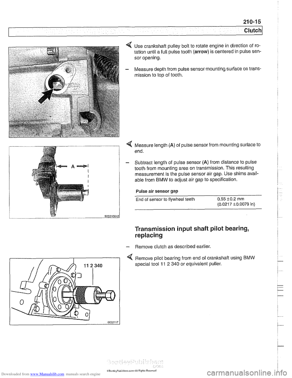
Use crankshaft pulley bolt to rotate engine in direction of ro-
tation until a full pulse tooth
(arrow) is centered in pulse sen-
sor opening.
Measure depth from pulse sensor mounting surface on trans-
mission to top of tooth.
Q Measure length (A) of pulse sensor from mounting surface to
end.
- Subtract length of pulse sensor (A) from distance to pulse
tooth from mounting area on transmission. This resulting
measurement is the pulse sensor air gap. Use shims avail-
able from
BMW to adjust air gap to specification.
Pulse air sensor gap
End of sensor to flywheel teeth 0.55 i-0.2 rnrn
(0.0217 i0.0079 in)
Transmission input shaft pilot bearing,
replacing
- Remove clutch as described earlier.
4 Remove pilot bearing from end of crankshaft using BMW
special tool 11 2 340 or equivalent puller.
Page 579 of 1002
Downloaded from www.Manualslib.com manuals search engine
Manual Transmission
Input shaft seal, replacing
(transmission removed)
- Remove transmission from vehicle as described later in this
group.
- Remove clutch release bearing end release bearing lever
from inside bellhousing.
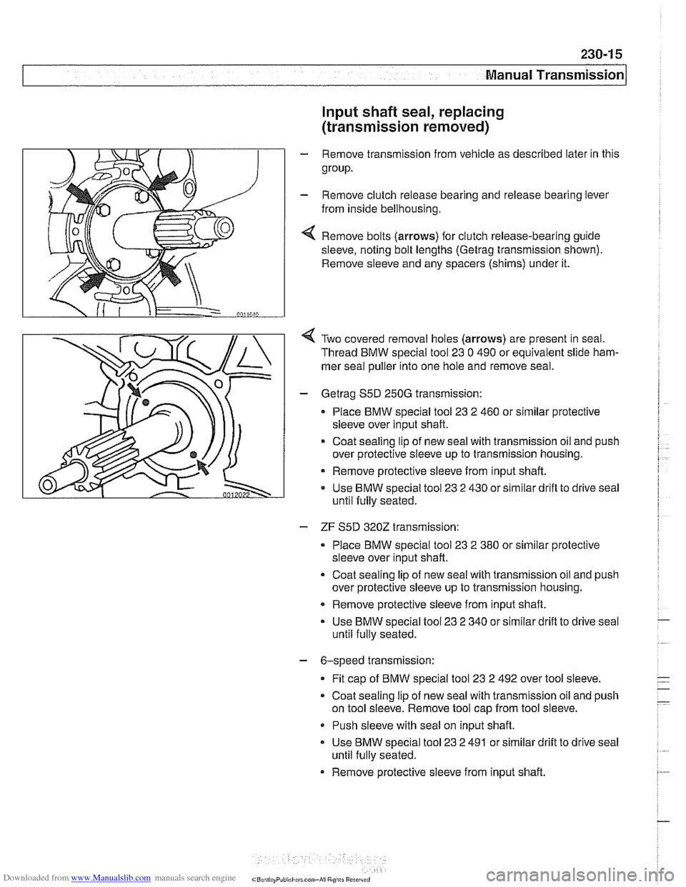
4 Remove bolts (arrows) for clutch release-bearing guide
sleeve, noting bolt lengths
(Getrag trensmission shown).
Remove sleeve and any spacers (shims) under it.
Two covered removal holes (arrows) are present in seal.
Thread BMW special tool
23 0 490 or equivalent slide ham-
mer seal puller into one hole and remove seal.
- Getreg S5D 250G transmission:
Place BMW special tool
23 2 460 or similar protective
sleeve over input shaft.
Coat sealing lip of new
seel with trensmission oil and push
over protective sleeve up to transmission housing.
Remove protective sleeve from input shaft.
Use BMW special tool
23 2 430 or similar drifl to drive seal
until fully seated.
- ZF S5D 3202 transmission:
Place BMW special tool
23 2 380 or similar protective
sleeve over input shaft.
Coat sealing lip of new seal with transmission oil and push
over protective sleeve up to transmission housing.
* Remove protective sleeve from input shaft.
Use BMW special tool
23 2 340 or similar drift to drive seal
until fully seated.
- 6-speed transmission:
Fit
cap of BMW special tool 23 2 492 over tool sleeve.
Coat sealing
lip of new seal with transmission oil and push
on tool sleeve. Remove tool cap from tool sleeve.
- Push sleeve with seal on input shaft.
- Use BMW special tool 23 2 491 or similar drift to drive seel
until fully seated.
Remove protective sleeve from input shaft.
Page 582 of 1002
Downloaded from www.Manualslib.com manuals search engine
230-1 8
Manual Transmission
- Unbolt clutch slave cylinder from side of transmission. Do not
disconnect fluid hose. Suspend slave cylinder from chassis
using stiff wire.
CA UTIOG
Unbolt clutch slave cylinder slowly to prevent air being
drawn into hydraulic system.
. Do not operate clutch pedal with slave cylinder re-
moved from transmission.
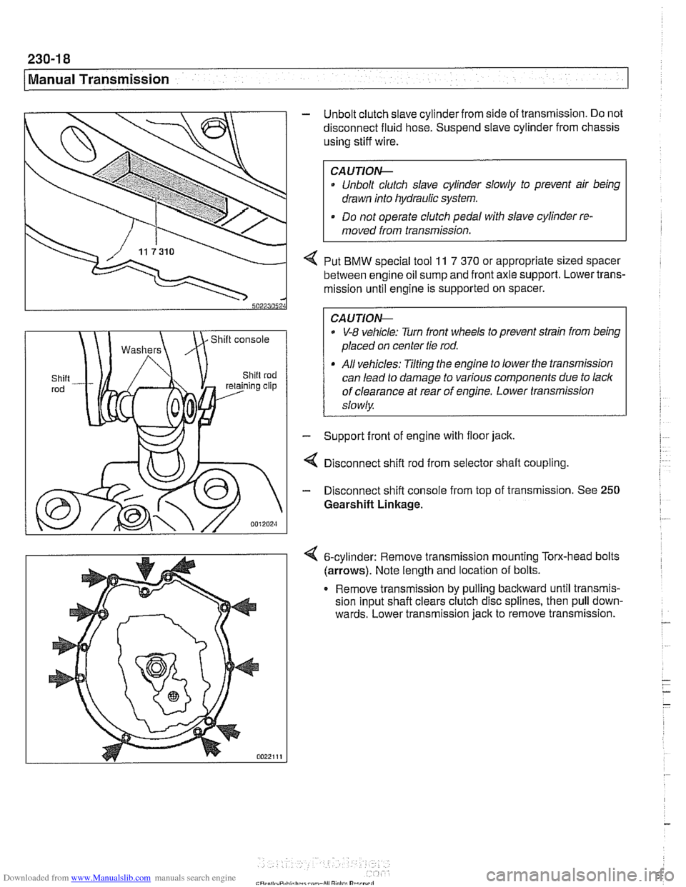
4 Put BMW special tool 11 7 370 or appropriate sized spacer
between engine oil sump and front axle support. Lower trans-
mission until engine is supported on spacer.
0 V-8 vehicle: Turn front wheels to prevent strain from being
placed on center tie rod.
All vehicles: Tilting the engine to lower the transmission
can lead to damage to various components due to lack
of clearance at rear of engine. Lower transmission
slowly
- Support front of engine with floor jack.
4 Disconnect shift rod from selector shaft coupling
- Disconnect shift console from top of transmission. See 250
Gearshift Linkage.
6-cylinder: Remove transrnisslon mounting Torx-head bolts
(arrows). Note length and locatlon of bolts.
Remove
transrnlssion by pulling backward untll transmls-
sion Input shaft clears clutch d~sc spl~nes, then pull down-
wards. Lower
transmlsslon jack to remove transrnlsslon. -
- - -
-