open hood BMW 540i 2000 E39 Workshop Manual
[x] Cancel search | Manufacturer: BMW, Model Year: 2000, Model line: 540i, Model: BMW 540i 2000 E39Pages: 1002
Page 335 of 1002
Downloaded from www.Manualslib.com manuals search engine
... . . Lubrication sy=
Upper oil pan, removing and installing (V-8)
The engine oil pan removal procedure requires that the en-
gine be supported from the top and the front suspension
sub-
frame be lowered.
- Disconnect negative (-) battery cable
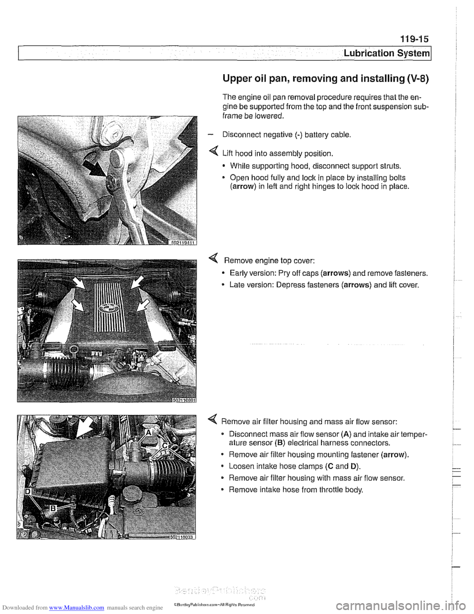
4 Lift hood into assembly position.
- While supporting hood, disconnect support struts.
Open hood
fully and lock in piace by installing bolts
(arrow) in left and right hinges to lock hood in place
4 Remove engine top cover:
- Early version: Pry off caps (arrows) and remove fasteners.
Late version: Depress fasteners (arrows) and lift cover.
4 Remove air filter housing and mass air flow sensor:
Disconnect mass air flow sensor
(A) and intake air temper-
ature sensor
(B) electrical harness connectors.
Remove air filter housing mounting fastener (arrow)
Loosen
intake hose clamps (C and D).
Remove air filter housing with mass air flow sensor.
Remove intake hose from throttle body.
Page 548 of 1002
Downloaded from www.Manualslib.com manuals search engine
21 0-6
1 Clutch
Hydraulic system, bleeding
(using
BMW special tool 21 5 030)
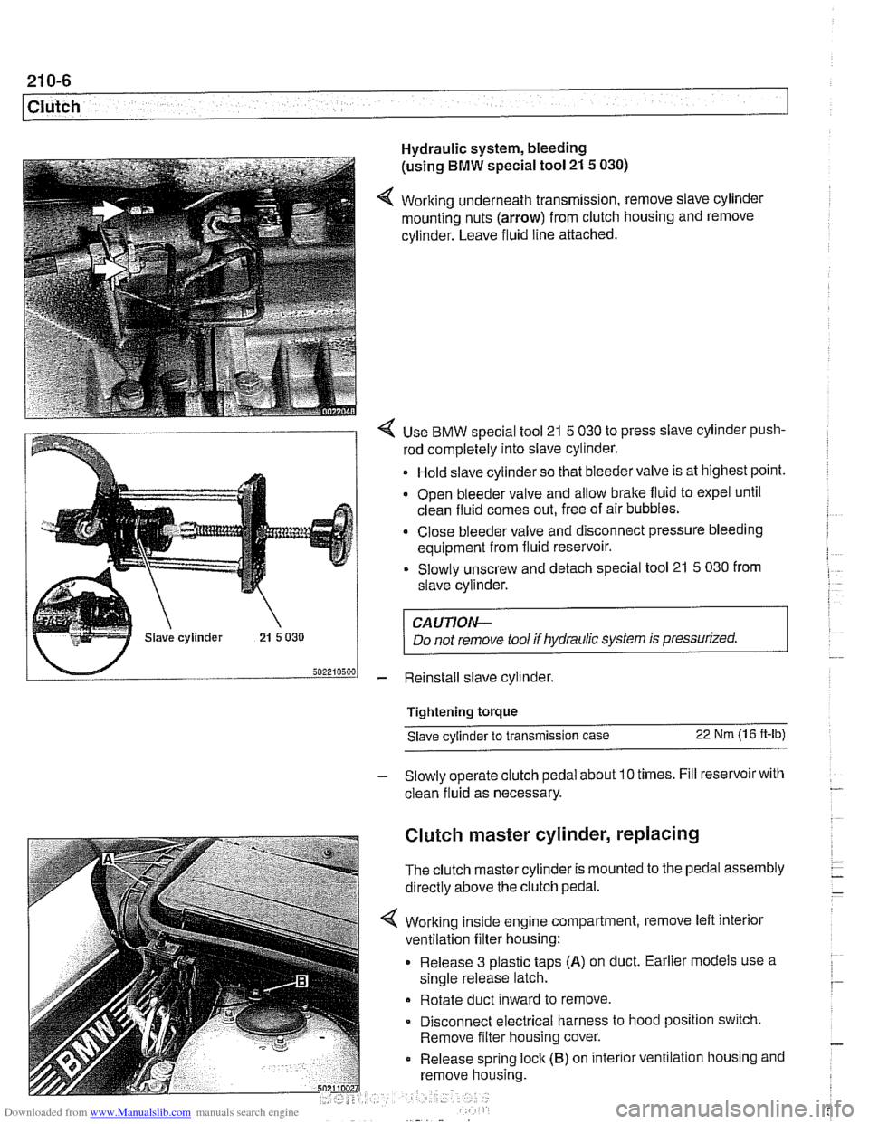
4 Working underneath transmission, remove slave cylinder
mounting nuts (arrow) from clutch housing and remove
cylinder. Leave fluid line attached.
4 Use BMW special tool 21 5 030 to press slave cylinder push-
rod completely into slave cylinder.
Hold slave cylinder so that bleeder valve is at highest point.
Open bleeder valve and allow brake fluid to expel until
clean fluid comes out, free of air bubbles.
* Close bleeder valve and disconnect pressure bleeding
equipment from fluid reservoir.
Slowly unscrew and detach special tool 21
5 030 from
slave cylinder.
CAUTION-
Do not remove tool if hydraulic system is pressurized.
- Reinstall slave cylinder.
Tightening torque Slave cylinder to transmission case
22 Nm (1 6 ft-lb)
- Slowly operate clutch pedal about 10 times. Fill reservoir with
clean fluid as necessary.
Clutch master cylinder, replacing
The clutch master cylinder is mounted to the pedal assembly
directly above the clutch pedal.
Working inside engine compartment, remove left interior
ventilation filter housing:
Release 3 plastic taps
(A) on duct. Earlier models use a
single release latch.
Rotate duct inward to remove
Disconnect electrical harness to hood position switch.
Remove filter housing cover.
Release spring
loclc (B) on interior ventilation housing and
remove housing.
Page 771 of 1002
Downloaded from www.Manualslib.com manuals search engine
Brakes
Brakes, bleeding
The procedure below requires a BMW Service Tester (DIS-
pluslGTl/MoDiC).
- Determine type of traction control (ASC, DSC with precharge
pump, DSC without precharge pump). Be sure to use correct
specification brake fluid, according to application table below.
Brake fluid applications
ABS I ASC and ABS / DSC models DOT 4 brake fluid
with precharge pump (to 911998)
ABS I DSC models without precharge DOT 4 low viscosity
pump (911998 and later) brake
fluid
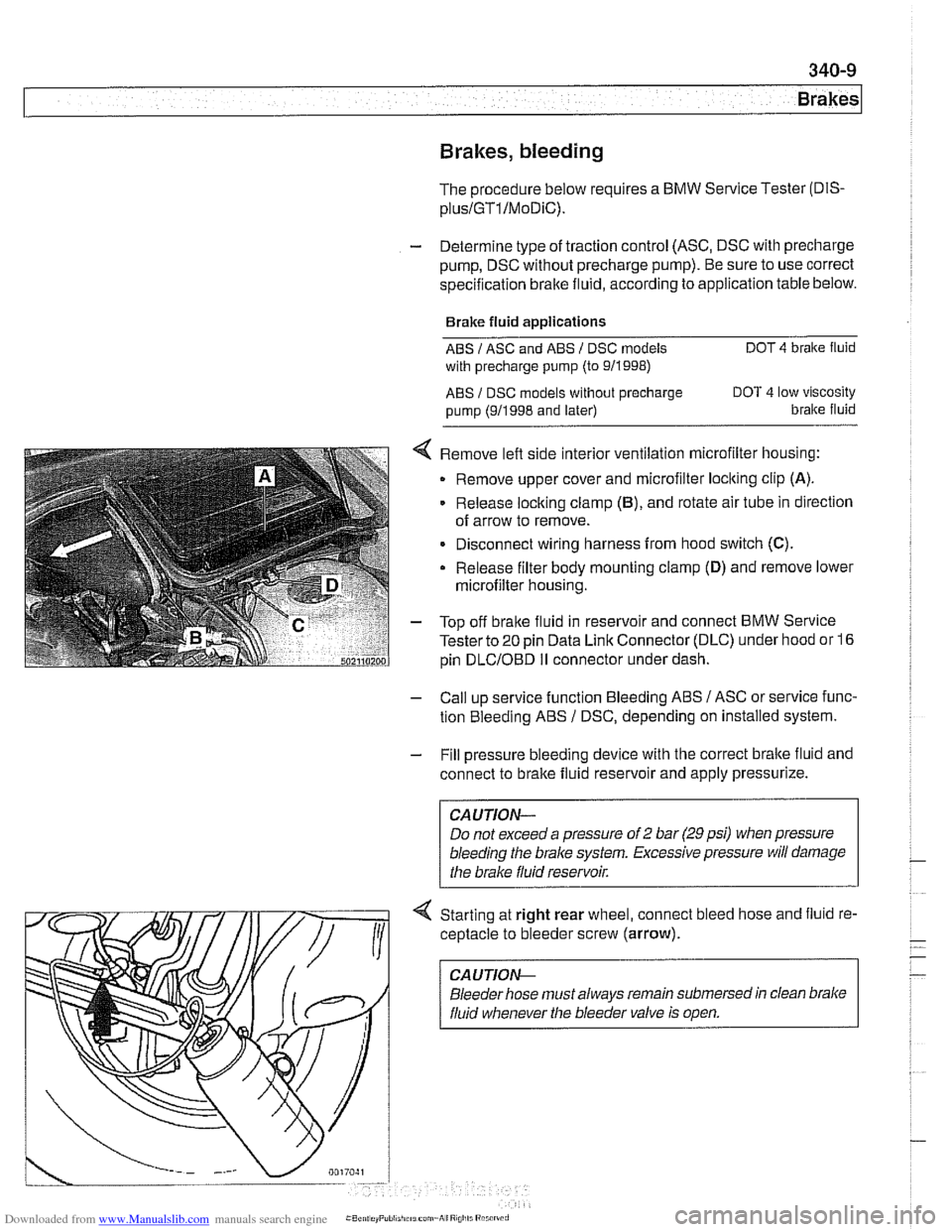
< Remove left side interior ventilation microfilter housing:
Remove upper cover and microfilter loclting clip
(A).
Release locking clamp (B), and rotate air tube in direction
of arrow to remove.
Disconnect wiring harness from hood switch
(C).
Release filter body mounting clamp (D) and remove lower
microfilter housing.
- Top off bralte fluid in reservoir and connect BMW Service
Tester to
20 pin Data Link Connector (DLC) under hood or 16
pin
DLCIOBD I1 connector under dash.
- Call up service function Bleeding ABS / ASC or service func-
tion Bleeding ABS
/ DSC, depending on installed system.
- Fill pressure bleeding device with the correct brake fluid and
connect to brake fluid reservoir and apply pressurize.
Do not exceed a pressure of
2 bar (29 psi) when pressure
bleeding the
brake system. Excessive pressure will damage
4 Starting at right rear wheel, connect bleed hose and fluid re-
ceptacle to bleeder screw (arrow).
CA UTlON-
Bleeder hose must always remain submersed in clean brake
fluid whenever the bleeder valve is open.
Page 779 of 1002
Downloaded from www.Manualslib.com manuals search engine
Brakes
Master cylinder, removing and installing
CAUTlOI\C
Brake fluid is highly corrosive and dangerous to the environ-
ment. Dispose of it properly.
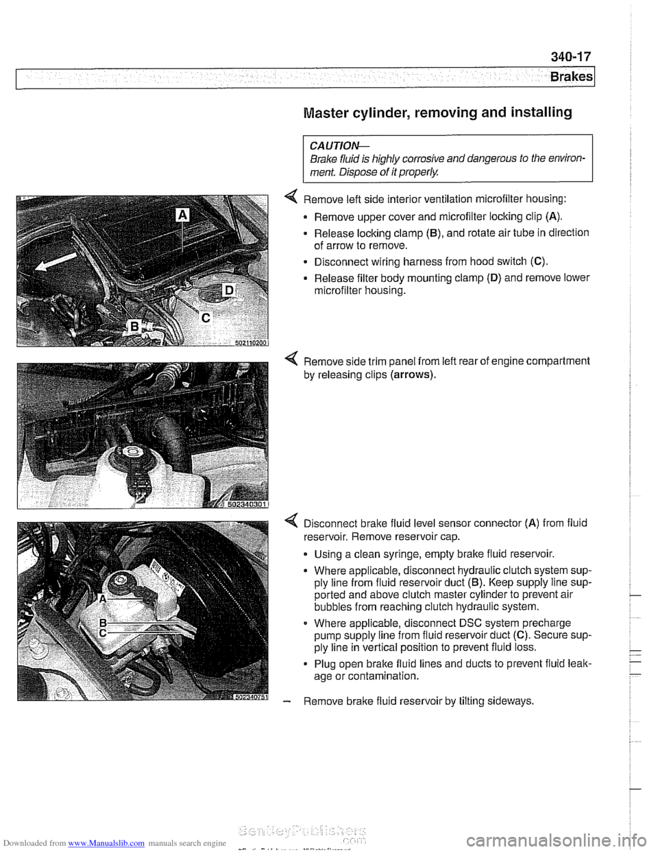
4 Remove left side interior ventilation microfilter housing:
Remove upper cover and microfilter locking clip
(A).
- Release locking clamp (B), and rotate air tube in direction
of arrow to remove.
Disconnect wiring harness from hood switch
(C).
Release filter body mounting clamp (D) and remove lower
microfilter housing.
4 Remove side trim panel from left rear of engine compartment
by releasing clips
(arrows).
4 Disconnect bralte fluid level sensor connector (A) from fluid
reservoir. Remove reservoir cap.
. Using a clean syringe, empty bralte fluid reservoir.
Where applicable, disconnect hydraulic clutch system sup-
ply line from fluid reservoir duct
(5). Keep supply line sup-
ported and above clutch master cylinder to prevent air
bubbles from reaching clutch hydraulic system.
Where applicable, disconnect DSC system precharge
pump supply line from fluid reservoir duct
(C). Secure sup-
ply line in vertical position to prevent fluid loss.
Plug open brake fluid lines and ducts to prevent fluid leak-
age or contamination.
- Remove brake fluid reservoir by tilting sideways.
Page 810 of 1002
Downloaded from www.Manualslib.com manuals search engine
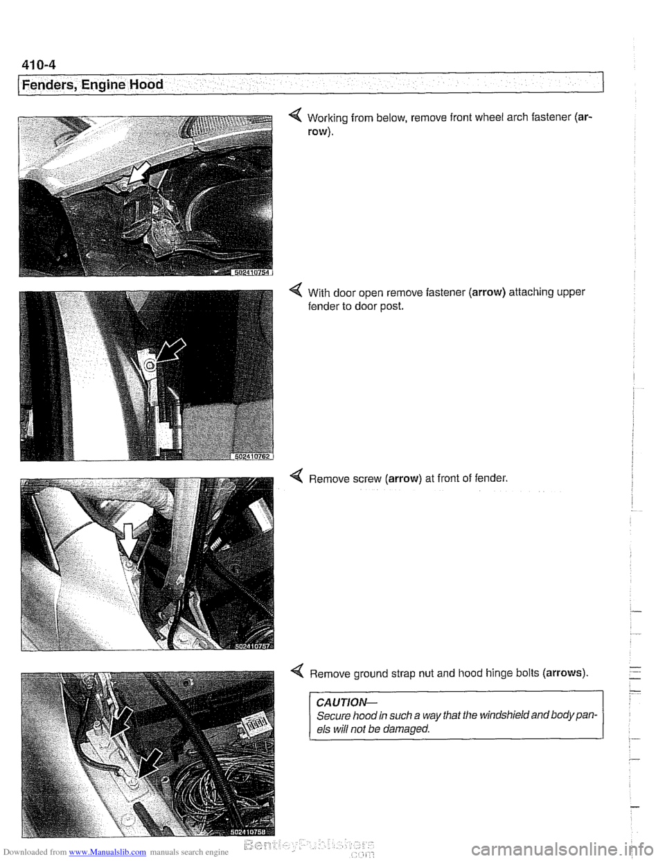
41 0-4
Fenders, Engine Hood
Working from below, remove front wheel arch fastener (ar-
row).
With door open remove fastener
fender to door post. (arrow) attaching upper
Remove screw
(arrow) at front of fender.
Remove ground strap nut and hood hinge bolts
(arrows)
CAUTION-
Secure hood in such a way that the windshield and body pan-
els
wiN not be damaged.
Page 812 of 1002
Downloaded from www.Manualslib.com manuals search engine
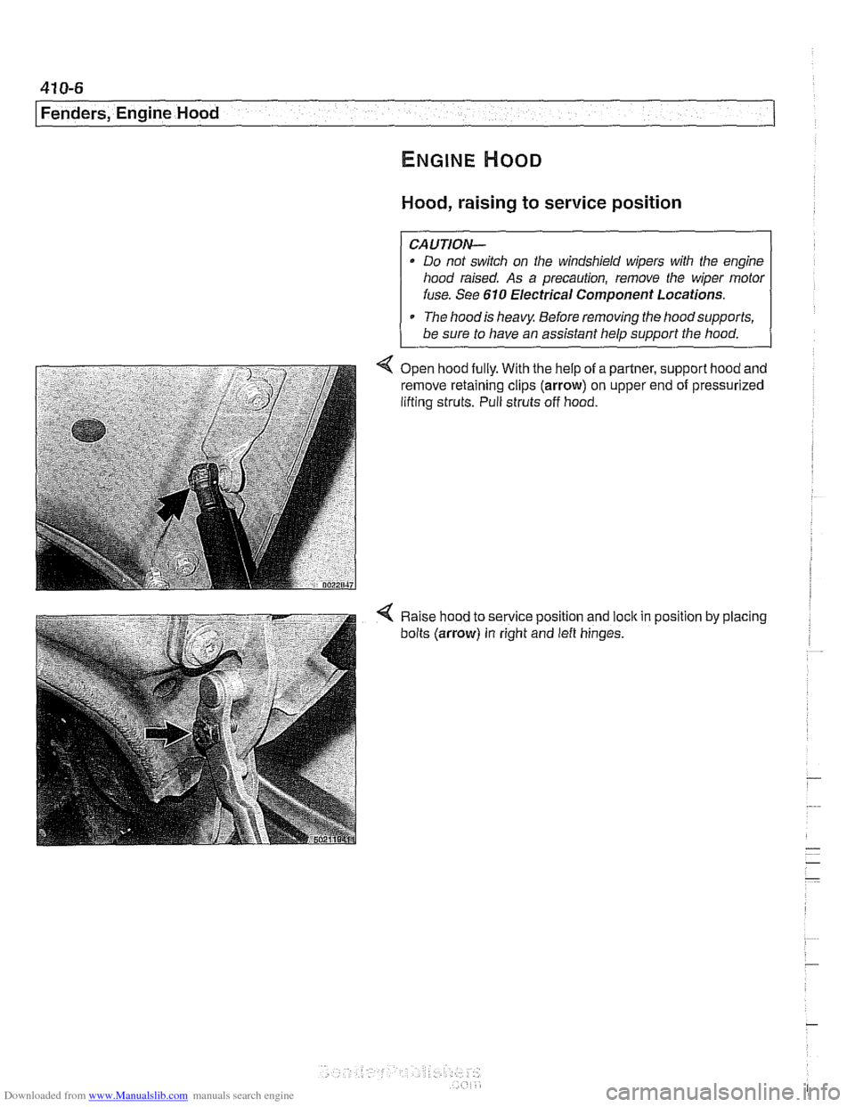
Hood, raising to service position
CAUTION-
Do not switch on the windshield wipers with the engine
hood raised. As a precaution, remove the wiper
motor
fuse. See 610 Electrical Component Locations.
The
hoodis heavy Before removing the hoodsupports,
be sure to have an assistant help support the hood.
< Open hood fully. With the help of a partner, support hood and
remove retaining clips (arrow) on upper end of pressurized
lifting struts. Pull struts off hood.
< Raise hood to service position and loclc in position by placing
bolts (arrow) in right and
left hinges.
Page 813 of 1002
Downloaded from www.Manualslib.com manuals search engine
Fenders, Engine ~ood/
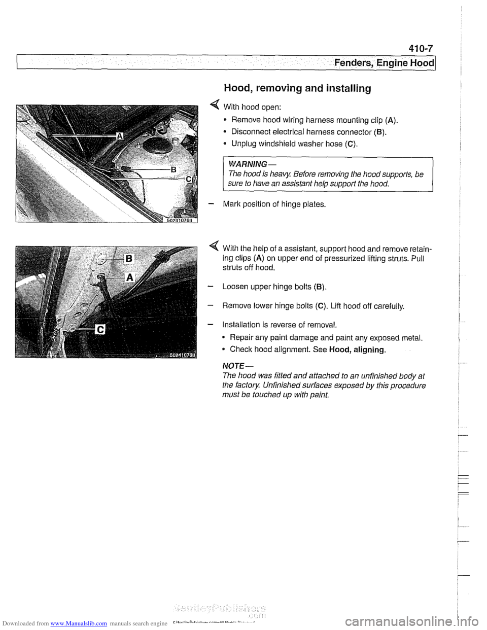
Hood, removing and installing
With hood open:
Remove hood wiring harness mounting clip
(A)
Disconnect electrical harness connector (B).
Unplug windshield washer hose (C).
WARNING-
The hood is heavy Before removing the hoodsupports, be
sure to have an assistant help
support the hood.
Mark position of hinge plates.
With the help of a assistant, support hood and remove retain-
ing clips
(A) on upper end of pressurized lifting struts. Pull
struts off hood.
Loosen upper hinge bolts
(B)
Remove lower hinge bolts (C). Lift hood off carefully.
Installation is reverse of removal.
* Repair any paint damage and paint any exposed metal
Check hood alignment. See
Hood, aligning.
NOTE-
The hood was fitted and attached to an unfinished body at
the factory Unfinished
sun'aces exposed by this procedure
must be touched up with paint,
Page 817 of 1002
Downloaded from www.Manualslib.com manuals search engine
Fenders, Ensine HOO~I
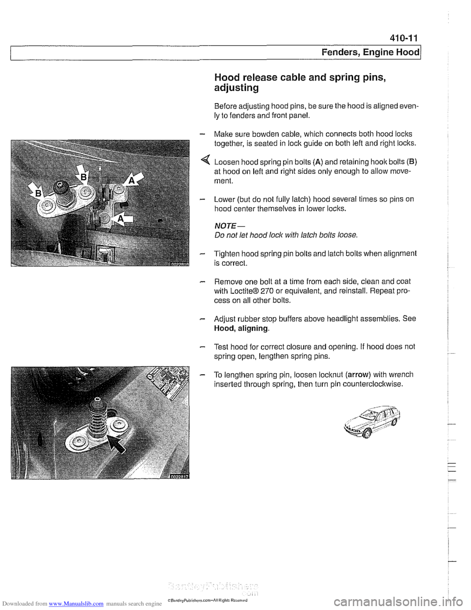
Hood release cable and spring pins,
adjusting
Before adjusting hood pins, be sure the hood is aligned even-
ly to fenders and front panel.
- Malte sure bowden cable, which connects both hood loclts
together, is seated in lock guide on both left and right loclts.
4 Loosen hood spring pin bolts (A) and retaining hoolt bolts (B)
at hood on left and right sides only enough to allow move-
ment.
- Lower (but do not fully latch) hood several times so pins on
hood center themselves in lower loclts.
NOTE-
Do not let hood lock with latch bolts loose
- Tighten hood spring pin bolts and latch bolts when alignment
is correct.
- Remove one bolt at a time from each side, clean and coat
with
LoctiteB 270 or equivalent, and reinstall. Repeat pro-
cess on all other bolts.
- Adjust rubber stop buffers above headlight assemblies. See
Hood, aligning.
- Test hood for correct closure and opening. If hood does not
spring open, lengthen spring pins.
- To lengthen spring pin, loosen locltnut (arrow) with wrench
inserted through spring, then turn pin counterclocltwise.
Page 864 of 1002
Downloaded from www.Manualslib.com manuals search engine
Exterior Trim, Bumpers 1
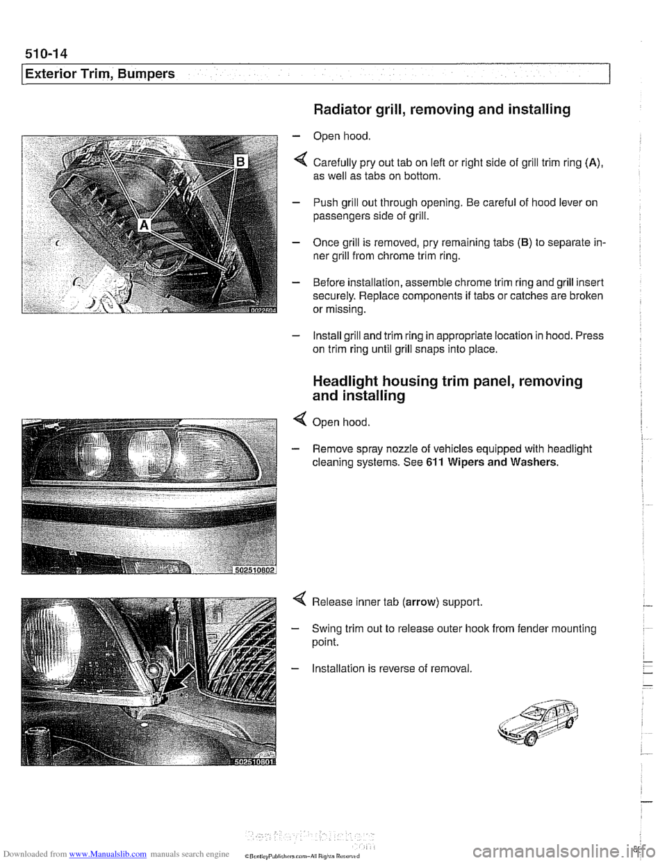
Radiator grill, removing and installing
- Open hood
4 Carefully pry out tab on lefl or right side of grill trim ring (A),
as well as tabs on bottom.
- Push grill out through opening. Be careful of hood lever on
passengers side of grill.
- Once grill is removed, pry remaining tabs (B) to separate in-
ner grill from chrome trim ring.
- Before installation, assemble chrome trim ring and grill insert
securely. Replace components
if tabs or catches are brolten
or missing.
- Install grill and trim ring in appropriate location in hood. Press
on trim ring until grill snaps into place.
Headlight housing trim panel, removing
and installing
4 Open hood
- Remove spray nozzle of vehicles equipped with headlight
cleaning systems. See
611 Wipers and Washers.
Release inner tab (arrow) support.
Swing trim out to release outer hook
point. from fender mounting
Installation is reverse of removal
Page 994 of 1002
Downloaded from www.Manualslib.com manuals search engine
4 INDEX
Door window anti-trap
512-4 convenience openinglclosing 512.4
regulator and motor 512-1 1
service
512-5 switches 512-3
see also Switches
Double
VANOS see VANOS
Drive
axle
CV joint 331-15 CV joint boot 331-15
rernovinglinstalling 331-14
Drive belt
see Maintenance
Driveabiiity troubleshooting
100-4
Driveaway protection
see EWS (eiectronic immobilization)
Driveshaft aligning
260-7
center bearing, replacing 260-12 CV joint, replacing 260-14
itex-disc, replacing 260-1 1
iront centering guide, replacing 260-13
rernovinglinstailing 260-6
lroubleshooting 260-3
U-joint 260-3
DSC
see Braires
DTC (diagnostic trouble code)
OBD-8
DWA
see Anti-theft alarm
ECM (engine control module)
see 130 under appropriate
iuei
injection system
ECT (engine coolant temperature)
sensor see 130 under appropriate
iuei
injection system
EDK adaptation
130-69
MS 43.0 130-35
EHC see Electronic iieigiit control (EHC)
Electric cooling fan
see Cooling system, cooling
fan
see also Cooiing system, eiectric fan
Electrical switches
see Switches
Electrical system abbreviations
600-14 bus System 600-4
component location table 610-3
components
photos
610-36
Sport Wagon 610-81 engine 121-2
troubleshooting 600-15
voltage and polarily 600-5 wire color codes 600-12
wiring diagrams 600-12
Electrical wiring diagrams
ELE-1
Eiectricaliy heated thermostat
(characteristic map)
170-4
Eiectronic height control (EHC)
300-8, 330-44
Eiectronic immobilization
see EWS (electronic immobilization)
Eiectronics box
(E-box)
610-37
Emergencies
010-18
Emergency brake see
BraBes, parking brake Engine
see also Cylinder head and valvetrain
applications
100-2
compression, testing 113-5
cooling see Cooiing system
crankshaft front oil seai
see Crankshaft oil seals
cyiinder leak-down test 113-8
diagnostic testing 113-1
drive belts
see Maintenance
driveability troubleshooting
100-4
engine management systems 100-2
see also Ignition
see also Fuel injection
fuel supply
130-6
ground connections 100-5
see also 61 0 identilying ieatures 100-3
lubrication svstem
see
~ubricetion system
mount
on-board diagnostics
OBD-I
oxygensensor
see Fuel injection
see also Exhaust system
Dreventive maintenance
see Maintenance
removal/installation
Engine control module (ECM)
see 130 under appropriate iuel
injection system
Engine cooiant temperature (ECT)
sensor see 130 under appropriate iuel
injection
system
Engine cooling fan
see Cooiing system, electric fan
Engine hood
41
0-6 raising to service position 410-6
Engine troubleshooting
see Engine, driveability troubleshooting
EVa~oratiVe control svstem
160-3 see also 130 under aDDroDriate iuel
injection system
Evaporator see
NC
Evaporator temperature sensor see
NC