warning BMW M3 1992 E36 Workshop Manual
[x] Cancel search | Manufacturer: BMW, Model Year: 1992, Model line: M3, Model: BMW M3 1992 E36Pages: 759
Page 253 of 759
NOTE-
The
traction
control
system
referred
to
as
AST
(all
sea-
son
traction)
may
also
be
referred
to
as
ASC
(Automat-
ic
Stability
Control)
and
ASC+T
(Automatic
Stability
Control+Traction)
.
The
AST
system
improves
traction
by
electronically
apply-
ing
the
rear
brakes
when
therear
drive
wheels
are
spinning
at
a
faster
rate
than
the
front
wheels
.
The
combined
ABS/AST
control
module,
operating
through
the
ABS
hydraulic
control
unit,
modulates
braking
force
at
therear
wheels
.
In
addition,
AST
uses
retarded
ignition
timing
and
an
auxil-iary
engine
throttle
plate
to
reduceengine
torque
and
maintain
vehicle
stability
.
The
auxiliary
throttle
plate
is
held
open
by
spring
pressure
.
The
AST
system
actívates
the
auxiliary
throttie
position
motor
(ADS)
to
cose
the
AST
throttle
as
needed
.
This
reduces
the
volume
of
engine
intake
air
.
Due
to
the
throttle
closing
very
rapidly
during
AST
operationthe
driver
cannot
increase
theengine
power
output
regardless
of
how
far
theaccelerator
pedal
is
pushed
to
the
floor
.
The
auxiliary
throttle
plate
is
placed
ahead
of
the
conven-
tional
throttle
plate
in
the
throttle
body
.
Traction
control
also
comes
into
operationduringdecelera-
tion
.
Decelerating
on
snowy
or
icy
road
surfaces
can
lead
to
rear
wheel
slip
.
If
a
rear
wheel
startsto
drag
or
lock
up
when
the
throttle
is
closed
rapidly
orduringdownshifting,the
AST
system
can
limit
the
problem
by
advancing
the
ignition
timing
.
A
switch
on
the
center
console
is
used
to
togglethe
AST
on
or
off
.
The
AST
system
is
designed
to
be
maintenance
free
.
There
are
no
adjustments
that
can
be
made
.
Repair
and
trouble-
shooting
of
the
AST
system
requires
special
test
equipment
andknowledgeand
should
be
performed
only
by
an
autho-
rized
BMW
dealer
.
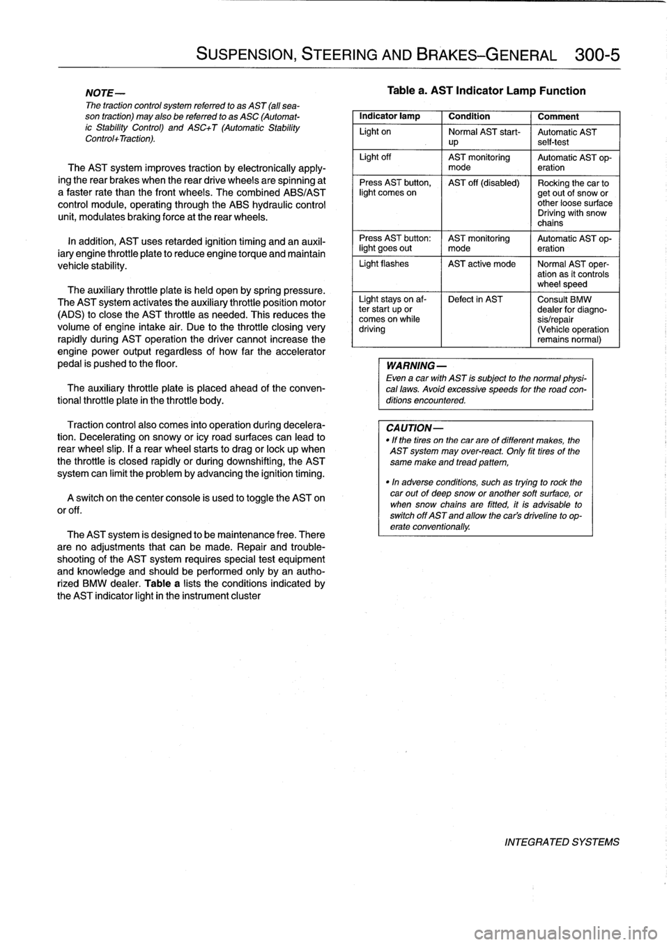
Table
a
lists
theconditions
indicated
by
the
AST
indicator
light
in
the
instrument
cluster
SUSPENSION,
STEERING
AND
BRAKES-GENERAL
300-5
Tablea
.
AST
Indicator
Lamp
Function
Indicator
lamp
1
Condition
1
Comment
Light
on
Normal
AST
start-
Automatic
AST
up
self-test
Light
off
AST
monitoring
Automatic
AST
op-
mode
eration
Press
AST
button,
AST
off
(disabled)
Rocking
the
car
tolight
comes
on
getout
of
snow
or
other
loose
surface
Driving
with
snow
chains
Press
AST
button
:
AST
monitoring
Automatic
AST
op-
light
goes
out
I
mode
eration
Light
flashes
AST
active
mode
I
Normal
AST
oper-
ation
as
it
controls
wheel
speed
Light
stays
on
af-
Defect
in
AST
Consult
BMW
ter
start
up
or
dealer
for
diagno-
comes
on
while
sis/repair
driving
(Vehicle
operation
remains
normal)
WARNING
-
Even
a
car
with
AST
is
subject
to
the
normal
physi-
cal
laws
.
Avoid
excessive
speeds
for
the
road
con-
ditions
encountered
.
CAUTION-
"
If
the
tires
on
the
carare
of
different
makes,
the
AST
system
may
over-react
.
Only
fit
tires
of
the
same
make
and
tread
pattem,
"In
adverse
conditions,
such
as
trying
to
rock
the
car
outof
deep
snow
or
another
soft
surface,
or
when
snow
chainsare
fitted,
it
is
advisable
to
switch
off
AST
and
allow
the
cars
driveline
to
op-
erate
conventionally
.
INTEGRATED
SYSTEMS
Page 258 of 759
310-2
FRONT
SUSPENSION
WARNING-
"
Physical
safety
could
be
impaired
if
procedures
described
here
areundertaken
without
the
proper
service
tools
and
equipment
.
Be
sure
to
have
the
right
tools
onhand
before
beginning
any
job
.
"
Do
notreuse
self-locking
nuts
or
bolts
.
They
are
designed
to
beused
only
once
and
may
fail
if
re-
used
.
Always
replace
self-locking
fasteners
any
timethey
are
loosenedor
removed
.
"
Do
not
install
bolts
and
nuts
coated
with
under-
coating
wax,
as
the
correct
tightening
torque
can-
not
beassured
.
Always
clean
the
threads
with
solventbefore
installation,
or
install
new
parts
.
"
Do
not
attempt
to
weld
or
straighten
any
suspen-
sion
components
.
Replace
damaged
parts
.
SHOCK
ABSORBERS
AND
SPRINGS
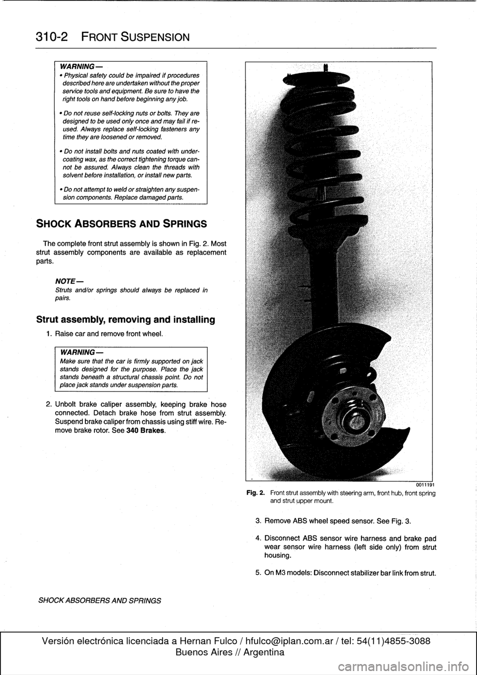
The
complete
front
strut
assembly
is
shown
in
Fig
.
2
.
Most
strut
assembly
components
are
available
asreplacement
parts
.
NOTE-
Struts
andlor
springs
shouldalways
be
replaced
in
parts
.
Strut
assembly,
removing
and
installing
1
.
Raisecar
and
remove
front
wheel
.
WARNING-
Make
sure
that
the
car
is
firmly
supported
on
jack
standsdesigned
for
the
purpose
.
Place
the
jack
standsbeneath
a
structural
chassis
point
Do
not
place
jack
stands
under
suspension
parts
.
2
.
Unbolt
brake
caliper
assembly,
keepingbrake
hose
connected
.
Detach
brake
hose
from
strut
assembly
.
Suspend
brake
caliper
from
chassis
using
stiff
wire
.
Re-
move
brake
rotor
.
See
340
Brakes
.
SHOCKABSORBERS
AND
SPRINGS
0011191
Fig
.
2
.
Front
strut
assembly
with
steering
arm,
front
hub,
front
spring
and
strut
upper
mount
.
3
.
Remove
ABS
wheelspeed
sensor
.
See
Fig
.
3
.
4
.
Disconnect
ABS
sensor
wire
harness
and
brake
pad
wear
sensor
wire
harness
(left
side
only)
from
strut
housing
.
5
.
OnM3
modeis
:
Disconnect
stabilizer
bar
link
from
strut
.
Page 260 of 759
310-
4
FRONT
SUSPENSION
Strut
assembly,
disassembling
and
assembling
-
Be
sure
upper
spring
pad
is
correctly
installed
to
upper
NOTE-
spring
plate
and
spring
end
is
correctly
seated
in
up-
Springs
andlor
struts
should
always
be
replaced
in
per
and
lower
spring
plates
.
pairs
.
"
Use
a
new
self-locking
top
(center)
nut
.
Tighten
nut
fui-
¡y
before
releasing
spring
compressor
.
Replacing
the
upper
strut
mount,
spring
and
strut
requires
"
Have
car
professionally
aligned
when
job
is
complete
.
that
the
strut
first
bedisassembled
.
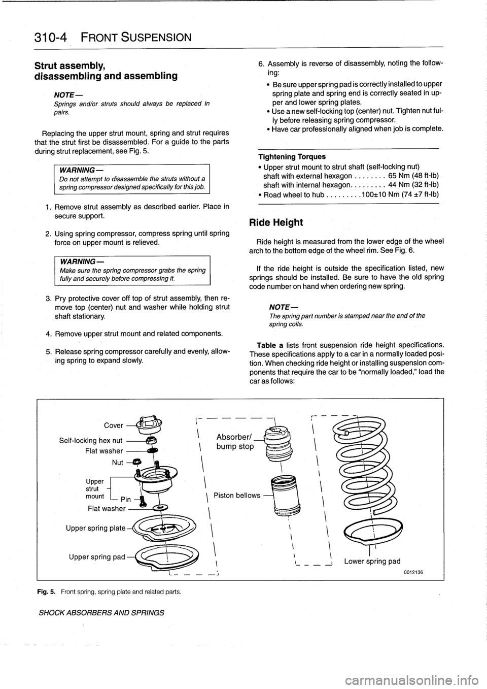
For
a
guide
to
the
parts
during
strut
replacement,
see
Fig
.
5
.
Tightening
Torques
WARNING-
"
Upper
strut
mount
to
strut
shaft
(seif-locking
nut)
Do
not,attempt
to
disassemble
thestruts
without
a
shaft
with
external
hexagon
......
..
65
Nm
(48
ft-1b)
springcompressordesignedspecificallyforthisjob
.
shaft
with
interna¡
hexagon
.......
..
44
Nm
(32
ft-Ib)
"
Road
wheel
to
hub
........
.100±10
Nm
(74
±7
ft-lb)
1
.
Remove
strut
assembly
as
described
earlier
.
Place
in
secure
support
.
Ride
Height
2
.
Using
spring
compressor,
compress
spring
until
spring
force
onupper
mount
is
relieved
.
Ride
height
is
measured
from
the
lower
edge
of
the
wheel
arch
to
the
bottom
edge
of
the
wheel
rim
.
See
Fig
.
6
.
WARNING
-
Make
sure
the
spring
compressor
grabs
the
spring
lf
the
ride
height
is
outside
the
specification
listed,
new
fully
and
securely
before
compressing
it
.
springs
should
be
installed
.
Be
sure
to
have
theold
spring
code
number
on
hand
when
ordering
new
spring
.
3
.
Pry
protective
cover
off
top
ofstrut
assembly,
then
re-
move
top
(center)
nut
andwasher
whileholding
strut
NOTE-
shaftstationary
The
spring
part
number
is
stamped
near
the
end
of
the
spring
cofls
.
4
.
Remove
upper
strut
mount
and
related
components
.
5
.
Release
spring
compressor
carefully
and
evenly,
allow-
ing
spring
lo
expand
slowly
1
Self-locking
hex
nut
Absorber/
Flat
washer
bump
stop
Nut
Cover
Upper
~
strut
mount
Pin
Z
Piston
bellows
Flat
washer
r
i
t1
~
1
Upper
spring
plate
1
1
1
Upper
spring
pad
I
1
-
,
Lower
spring
pad
-
Í
0012136
Fig
.
5
.
Front
spring,
spring
plate
and
related
parts
.
SHOCKABSORBERS
AND
SPRINGS
6
.
Assembly
is
reverse
of
disassembly,
noting
the
follow-
ing
:
Table
a
lists
front
suspension
ride
height
specifications
.
These
specifications
apply
to
a
car
in
a
normally
loaded
posi-
tion
.
When
checking
ride
height
or
installing
suspension
com-
ponents
that
require
thecar
to
be
"normally
loaded,"load
the
car
as
follows
:
Page 261 of 759
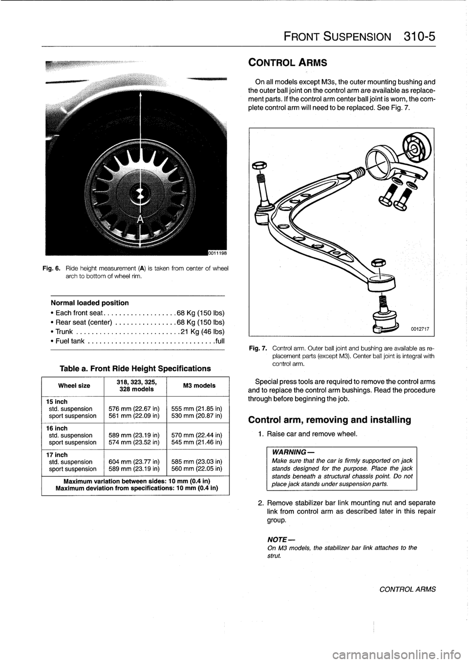
Fig
.
6
.
Ride
height
measurement
(A)
is
taken
from
centerof
wheel
archto
bottom
of
wheel
rim
.
Normal
loaded
position
"
Each
front
seat
...
...
.
..
..........
68Kg
(150
Ibs)
"
Rear
seat
(center)
...
.
.
...........
68Kg
(150
Ibs)
"
Trunk
..........
...
.
.
...........
.21
Kg
(46
lbs)
"
Fuel
tank
...
.
..
....
.
.
....................
.fuf
Tablea
.
Front
RideHeight
Specifications
318,323,325,
Wheel
size
M3
models
328
models
15
inch
std
.
suspension
576
mm
(22.67
in)
1555
mm
(21.85
in)
sport
suspension
~
561
mm
(22.09
in)
530
mm
(20
.87
in)
16
inch
std
.
suspension
589
mm
(23.19
in)
1570
mm
(22
.44
in)
sport
suspensíon
~
574
mm
(23.52
in)
545
mm
(21.46
in)
17
inch
std
.
suspension
604
mm
(23.77
in)
585
mm
(23
.03
in)
sport
suspension
~
589
mm
(23.19
in)
~
560
mm
(22
.05
in)
Maximum
variation
between
sides
:
10
mm
(0.4in)
Maximum
deviation
from
specifications
:
10
mm
(0
.4in)
FRONT
SUSPENSION
310-
5
CONTROL
ARMS
On
al¡
models
except
Mas,
theouter
mounting
bushing
and
theouter
ball
joint
on
the
control
arm
are
available
as
replace-
ment
parts
.
If
the
control
arm
center
ball
joint
is
worn,
the
com-
plete
control
arm
will
need
to
be
replaced
.
See
Fig
.
7
.
Fig
.
7
.
Control
arm
.
Outer
ball
joint
and
bushing
are
available
as
re-
placement
parts
(except
M3)
.
Center
ball
joint
is
integral
with
control
arm
.
Special
press
tools
are
requiredto
remove
the
control
arms
and
to
replace
the
control
arm
bushings
.
Read
the
procedure
through
before
beginning
the
job
.
Control
arm,
removing
and
installing
1
.
Raise
car
and
remove
wheel
.
WARNING-
Make
sure
that
thecar
is
firmly
supportedon
jack
standsdesigned
for
the
purpose
.
Place
the
jack
stands
beneath
a
structural
chassis
point
.
Do
not
place
jack
stands
undersuspension
parts
.
2
.
Remove
stabilizer
bar
link
mounting
nut
and
separate
link
from
control
arm
as
described
later
in
this
repair
group
.
NOTE-
On
M3
models,
the
stabilizer
bar
link
attaches
to
the
strut
.
CONTROL
ARMS
Page 262 of 759
310-
6
FRONT
SUSPENSION
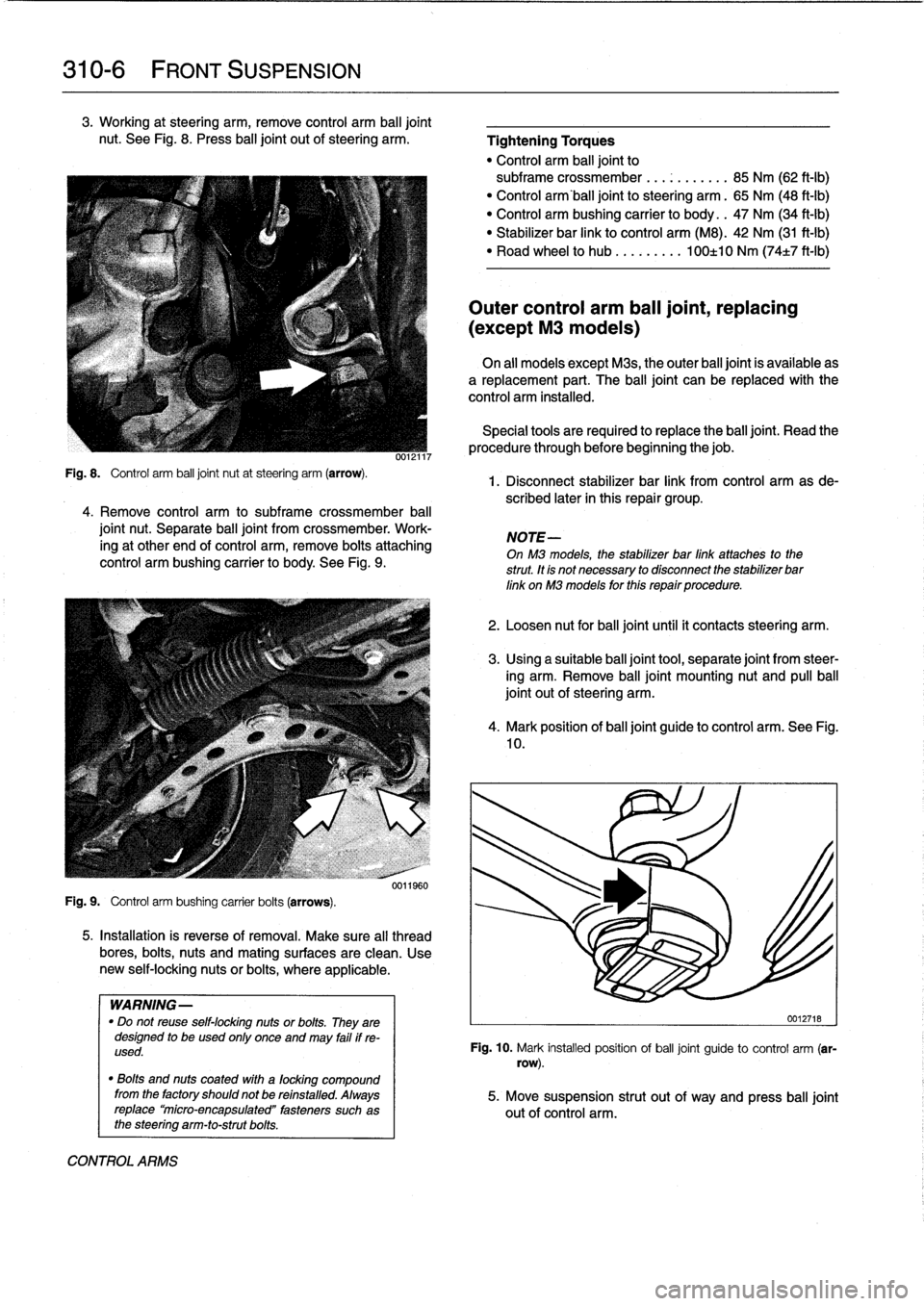
3
.
Working
at
steering
arm,
remove
control
arm
balljoint
nut
.
See
Fig
.
8
.
Press
ball
joint
out
ofsteering
arm
.
Fig
.
8
.
Control
arm
ball
joint
nut
at
steering
arm
(arrow)
.
4
.
Remove
control
arm
to
subframe
crossmember
ball
joint
nut
.
Separate
ball
joint
from
crossmember
.
Work-
ing
at
other
end
of
control
arm,
remove
bolts
attaching
control
arm
bushing
carrier
to
body
.
See
Fig
.
9
.
Fig
.
9
.
Control
arm
bushing
carrier
bolts
(arrows)
.
0012117
0011960
5
.
Installation
is
reverse
of
removal
.
Make
sure
al¡
thread
bores,
bolts,
nuts
and
mating
surfaces
are
clean
.
Use
new
self-locking
nutsor
bolts,
where
applicable
.
WARNING-
"
Do
not
reuse
self-locking
nuts
or
bolts
.
They
are
designed
to
be
used
only
once
and
may
failif
re-
used
.
"
Bolts
and
nuts
coated
with
a
focking
compound
from
the
factory
shouldnot
be
refnstalled
.
Always
replace`micro-encapsulated"
fasteners
such
as
the
steering
arm-to-strutbolts
.
CONTROL
ARMS
Tightening
Torques
"
Control
arm
balljoint
to
subframe
crossmember
.
..
...
...
.
.
85
Nm
(62
ft-Ib)
"
Control
arm'ball
joint
to
steering
arm
.
65
Nm
(48
ft-Ib)
"
Control
arm
bushing
carrier
to
body
.
.
47
Nm
(34
ft-Ib)
"
Stabilizer
bar
link
to
control
arm
(M8)
.
42
Nm
(31
ft-Ib)
"
Road
wheel
to
hub
.
...
...
.
.
100±10
Nm
(74±7
ft-Ib)
Outer
control
arm
ball
joint,
replacing
(except
M3
models)
On
all
models
except
Mas,
the
outer
balljoint
is
available
as
a
replacement
part
.
The
ball
joint
can
be
replaced
with
the
control
arm
installed
.
Special
tools
are
requiredto
replace
the
balljoínt
.
Read
the
procedure
through
before
beginning
thejob
.
1
.
Disconnect
stabilizer
bar
link
from
control
arm
asde-
scribed
later
in
this
repair
group
.
NOTE-
On
M3
models,
the
stabilizer
bar
link
attaches
to
the
strut
.
tt
fs
not
necessary
to
disconnect
the
stabilizer
bar
link
on
M3
models
for
thfs
repair
procedure
.
2
.
Loosen
nut
for
balljointuntil
it
contacts
steering
arm
.
3
.
Using
a
suitable
ball
joint
tool,
separate
joint
from
steer-
íng
arm
.
Remove
ball
joint
mounting
nut
and
pullball
joint
out
of
steering
arm
.
4
.
Mark
position
of
balljoint
guide
to
control
arm
.
See
Fig
.
10
.
0012718
Fig
.
10
.
Mark
installed
position
of
ball
joint
guide
to
control
arm
(sr-
row)
.
5
.
Move
suspension
strut
out
of
way
and
press
ball
joint
out
of
control
arm
.
Page 263 of 759
6
.
Installation
is
reverse
of
removal
.
"
Make
sure
control
arm
ball
joint
taper
bore
is
clean
and
free
of
any
corrosion
.
"
Press
new
balljoint
into
position,
making
sure
to
align
balljoint
guide
with
mark
made
earlier
.
"
Verify
that
locking
clip
on
new
ball
joint
faces
towards
center
of
vehicle
.
Tightening
Torques
"
Control
arm
ball
jointto
steering
arm
.
65
Nm
(48
ft-Ib)
"
Stabilizer
bar
link
to
control
arm
(M8)
42
Nm
(31
ft-Ib)
"
Road
wheel
to
hub
.
...
...
.
.
100±10
Nm
(74t7
ft-lb)
Control
arm
bushing,
replacing
Control
arm
bushings
should
aiways
be
replaced
in
pairs
and
the
two
bushings
and
bushing
carriers
should
have
the
same
markings,
indicating
same
manufacturer
.
1
.
Raisecar
.
WARNING-
Make
sure
that
the
car
is
firmly
supportedonjackstandsdesigned
for
the
purpose
.
Place
the
jackstands
beneath
a
structural
chassis
point
.
Do
not
place
jack
stands
undersuspension
parts
.
2
.
Unbolt
control
arm
bushing
carrier
from
body
.
3
.
Mark
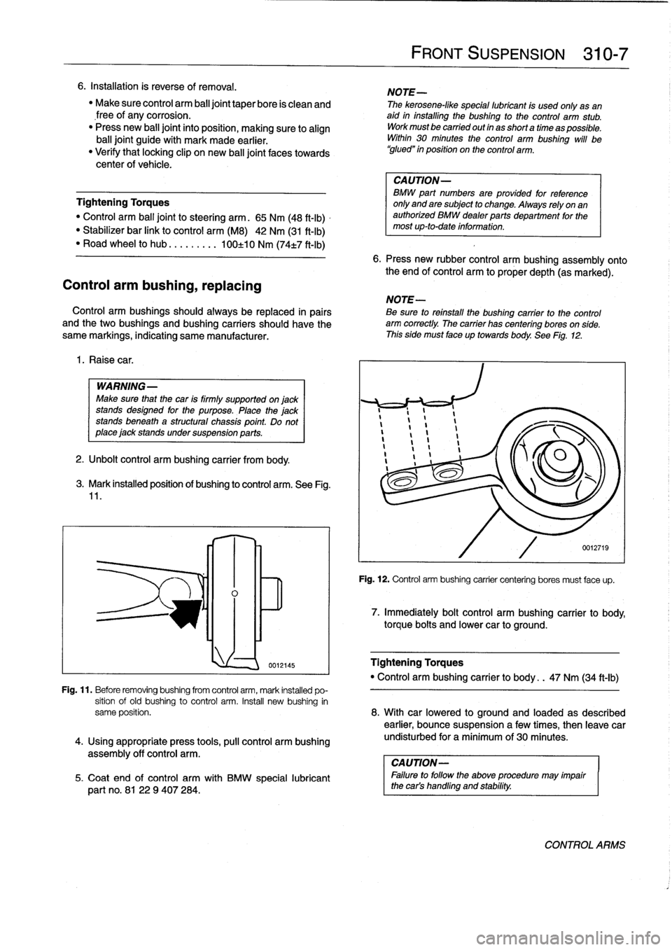
installed
position
of
bushing
to
control
arm
.
See
Fig
.
11
.
assembly
off
control
arm
.
lnl~
0012145
FRONT
SUSPENSION
310-
7
NOTE-
The
kerosene-like
special
lubricant
is
used
only
asan
aid
in
installing
the
bushing
to
the
control
arm
stub
.
Workmustbe
carried
out
in
as
short
a
time
as
possible
.
Within
30
minutes
the
control
arm
bushing
will
be
`glued"
in
position
on
the
control
arm
.
CAUTION-
BMW
part
numbers
areprovided
for
reference
only
and
are
subject
to
change
.
Always
rely
on
an
authorized
BMW
dealerparts
department
for
the
most
up-to-date
information
.
6
.
Press
new
rubber
control
arm
bushing
assembly
onto
the
end
of
control
arm
to
proper
depth
(as
marked)
.
NOTE-
Be
sure
toreinstall
the
bushing
carrier
to
the
control
arm
correctly
.
The
carrier
has
centering
bores
on
side
.
This
side
must
face
up
towards
body
.
See
Fig
.
12
.
Fig
.
12
.
Control
arm
bushing
carrier
centering
bores
must
face
up
.
7
.
Immediately
bolt
control
arm
bushing
carrier
to
body,
torque
boits
and
lower
car
to
ground
.
Tightening
Torques
"
Control
arm
bushing
carrier
to
body
.
.
47
Nm
(34
ft-ib)
Fig
.
11
.
Before
removingbushing
from
control
arm,
mark
installed
po-
sition
of
old
bushing
to
control
arm
.
Insta¡¡
new
bushing
in
same
position
.
8
.
With
car
lowered
to
ground
and
loaded
as
described
earlier,
bounce
suspensiona
few
times,
then
leave
car
4
.
Using
appropriate
press
tools,
pull
control
arm
bushing
undisturbed
for
a
minimum
of
30
minutes
.
CAUTION-
5
.
Coat
end
of
control
arm
with
BMW
special
lubricant
I
Failure
to
follow
the
above
procedure
may
impair
part
no
.
8122
9
407284
.
the
car's
handling
and
stability
.
CONTROLARMS
Page 264 of 759
310-
8
FRONT
SUSPENSION
FRONT
WHEEL
BEARINGS
The
front
wheel
bearings
are
permanently
sealed
and
re-
quire
no
maintenance
.
The
bearing
is
integral
with
the
wheel
hub
and
pressed
onto
the
steering
arm
stub
axle
.
Special
press
tools
are
requiredto
replace
the
front
wheel
bearings
.
Read
the
procedure
through
before
beginning
the
job
.
Front
wheel
bearing,
replacing
1
.
Raise
car
and
remove
wheel
.
WARNING-
Make
sure
that
the
car
is
firmly
supportedon
jack
stands
designed
for
the
purpose
.
Place
the
jack
stands
beneatha
structural
chassis
point
.
Do
not
place
jack
stands
under
suspension
parts
.
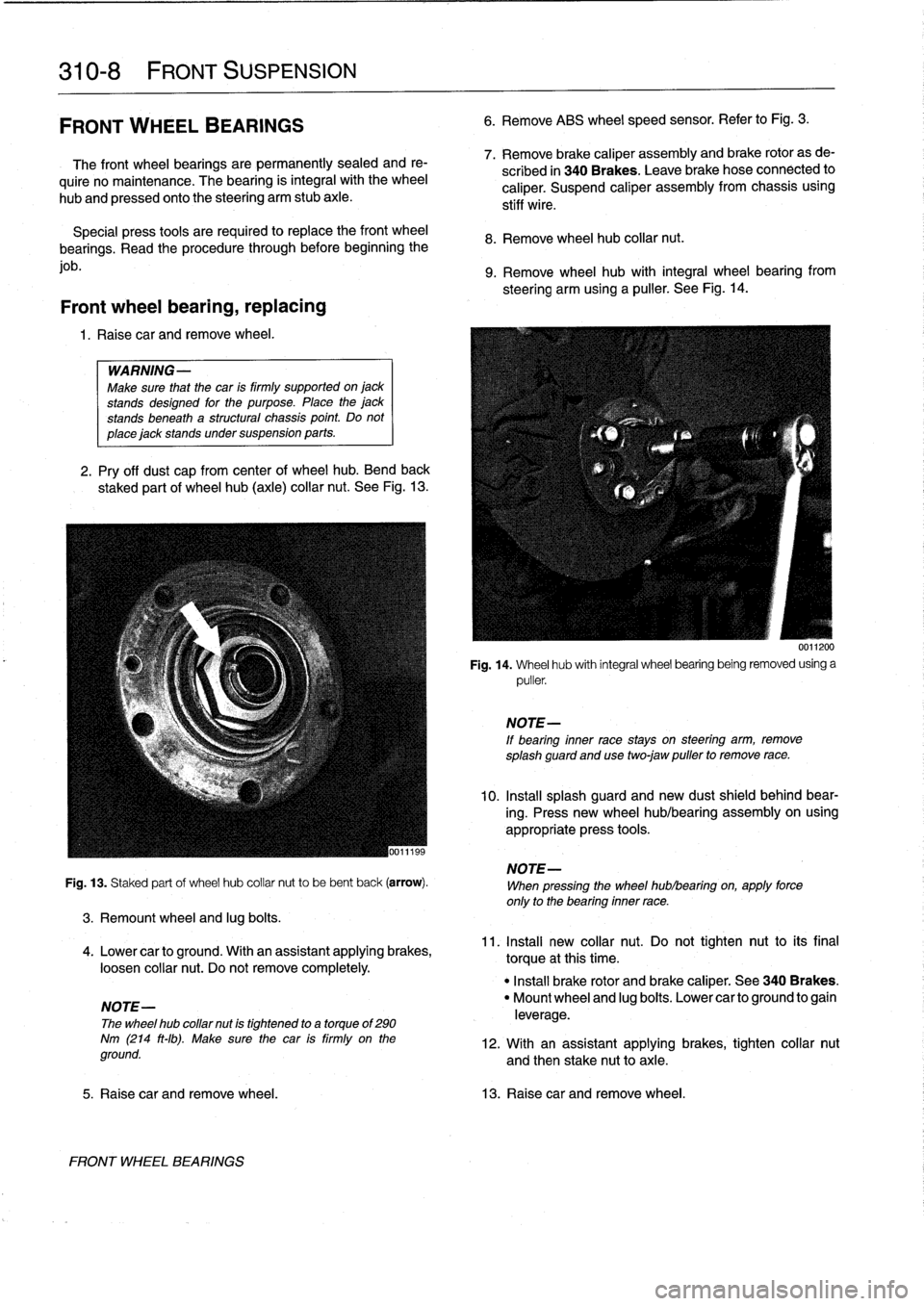
2
.
Pry
off
dust
cap
from
centerof
wheel
hub
.
Bend
back
staked
part
of
wheel
hub
(axle)
collar
nut
.
See
Fig
.
13
.
Fig
.
13
.
Staked
part
of
wheel
hub
collar
nut
to
be
bent
back
(arrow)
.
3
.
Remount
wheel
and
lug
bolts
.
4
.
Lower
canto
ground
.
With
an
assistant
applying
brakes,
loosen
collar
nut
.
Do
not
remove
completely
.
NOTE-
The
wheel
hub
collar
nut
is
tightened
to
a
torque
of
290
Nm
(214
ft-Ib)
.
Make
sure
the
car
is
firmly
on
the
ground
.
FRONT
WHEEL
BEARINGS
6
.
Remove
ABS
wheel
speed
sensor
.
Refer
to
Fig
.
3
.
7
.
Remove
brake
caliper
assembly
and
brake
rotor
as
de-
scribed
in
340
Brakes
.
Leave
brakehose
connected
to
caliper
.
Suspend
caliper
assembly
from
chassis
using
stiff
wire
.
8
.
Remove
wheel
hub
collar
nut
.
9
.
Remove
wheel
hub
with
integral
wheel
bearing
from
steering
arm
using
a
puller
.
See
Fig
.
14
.
0011200
Fig
.
14
.
Wheel
hub
with
integral
wheel
bearing
being
removed
using
a
puller
.
NOTE-
If
bearing
inner
race
stays
on
steering
arm,
remove
splash
guard
and
usetwo
jaw
puller
to
remove
race
.
10
.
Insta¡¡
splash
guard
and
new
dust
shield
behind
bear-
ing
.
Press
new
wheel
hub/bearing
assembly
on
using
appropriate
press
tools
.
NOTE-
When
pressing
the
wheel
hublbearing
on,
apply
force
only
to
the
bearing
inner
race
.
11
.
Install
new
collar
nut
.
Do
not
tighten
nut
to
its
final
torque
atthis
time
.
"
Install
brake
rotor
and
brake
caliper
.
See
340
Brakes
.
"
Mount
wheel
and
lug
boits
.
Lower
canto
ground
to
gain
leverage
.
12
.
With
an
assistant
applying
brakes,
tighten
collar
nut
and
then
stake
nut
toaxle
.
5
.
Raise
car
and
remove
wheel
.
13
.
Raisecar
and
remove
wheel
.
Page 265 of 759
STABILIZER
BAR
Stabilizer
bar,
removing
and
installing
Stabilizer
bar
link
arrangements
differ
slightly
among
mod-
els
.
In
most
models
the
links
attach
lo
the
control
arms
near
the
outboard
end
.
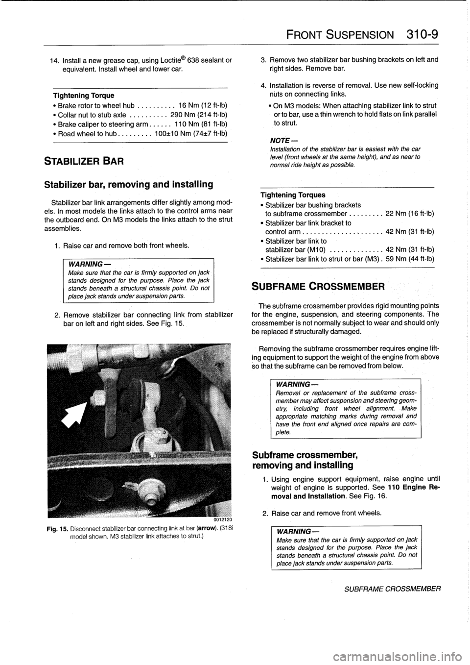
OnM3
models
the
links
attach
lo
the
strut
assemblies
.
1
.
Raise
car
and
remove
both
front
wheels
.
WARNING
-
Make
sure
that
the
car
is
firmly
supported
on
jack
stands
desígned
for
the
purpose
.
Place
the
jack
stands
beneath
a
structural
chassís
point
.
Do
not
place
jack
stands
under
suspension
parts
.
uul
Fig
.
15
.
Disconnect
stabilizer
bar
connecting
link
at
bar
(arrow)
.
(3181
model
shown
.
M3
stabilizer
link
attaches
lo
strut
.)
FRONT
SUSPENSION
310-
9
14
.
Insta¡¡
a
new
grease
cap,
using
Loctite
©
638
sealant
or
3
.
Remove
two
stabilizer
bar
bushing
brackets
on
left
and
equivalent
.
Insta¡¡
wheel
and
lower
car
.
right
sides
.
Remove
bar
.
4
.
Installation
is
reverse
of
removal
.
Use
new
seif-lockíng
Tightening
Torque
núts
on
connecting
links
.
"
Brake
rotor
lo
wheel
hub
..........
16
Nm
(12
ft-Ib)
"
On
M3
models
:
When
attaching
stabilizer
link
lostrut
"
Collar
nut
lo
stubaxle
.
.........
290
Nm
(214
ft-Ib)
orlobar,
usea
thin
wrench
lo
hold
flats
on
link
parallel
"
Brake
caliper
losteering
arm
......
110
Nm
(81
ft-Ib)
lo
strut
.
"
Road
wheel
lo
hub
...
...
.
.
.
100±10
Nm
(74t7
ft-Ib)
NOTE-
Installation
of
the
stabilizer
bar
is
easiest
with
thecar
leve¡
(front
wheels
at
the
same
height),
and
as
near
to
normal
ride
height
as
possible
.
Tightening
Torques
"
Stabilizer
bar
bushing
brackets
lo
subframe
crossmember
...
..
.
..
.
22
Nm
(16
ft-Ib)
"
Stabilizer
bar
link
bracket
lo
control
arm
................
.
.
.
.
.
42
Nm
(31
ft-1b)
"
Stabilizer
bar
link
lo
stabilizer
bar
(M10)
.............
.
42
Nm
(31
ft-Ib)
"
Stabilizer
bar
link
lostrut
or
bar
(M3)
.
59
Nm
(44
ft-Ib)
SUBFRAME
CROSSMEMBER
The
subframe
crossmember
provides
rigid
mounting'poínts
2
.
Remove
stabilizer
bar
connecting
link
from
stabilizer
for
the
engine,
suspension,
and
steering
components
.
The
baron
left
and
right
sides
.
See
Fig
.
15
.
crossmember
is
not
normally
subject
lo
wear
and
should
ohly
be
replaced
if
structurally
damaged
.
Removing
the
subframe
crossmember
requires
engine
lift-
ing
equipment
lo
support
theweight
of
tfhe
engine
from
above
so
that
the
subframe
can
be
removed
from
below
.
WARNING-
Removal
or
replacement
of
the
subframe
cross-
member
may
affect
suspension
and
steering
geom-
etry,
including
front
wheel
afignment
.
Make
appropriate
matching
marks
during
removal
and
have
the
front
end
aligned
once
repairs
are
com-
plete
.
Subframe
crossmember,
removing
and
installing
1
.
Using
enginesupport
equipment,
raise
engine
until
weight
of
engine
is
supported
.
See
110EngineRe-
moval
and
Installation
.
See
Fig
.
16
.
2
.
Raise
car
andremove
front
wheels
.
WARNING-
Make
sure
that
the
car
is
firmly
supportedon
jack
stands
desígned
for
the
purpose
.
Place
the
jack
stands
beneatha
structural
chassís
point
Do
not
place
jack
standsundersuspension
parts
.
SUBFRAME
CROSSMEMBER
Page 266 of 759
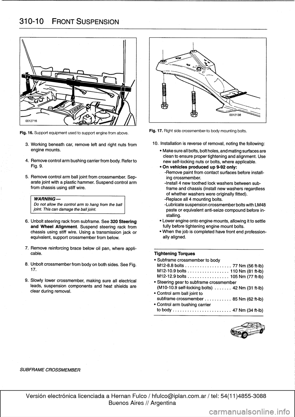
310-
1
0
FRONT
SUSPENSION
Fig
.
16
.
Supportequipment
used
to
support
engine
from
aboye
.
SUBFRAME
CROSSMEMBER
Fig
.
17
.
Right
side
crossmember-to
body
mounting
bolts
.
3
.
Working
beneath
car,
remove
left
and
right
nuts
from
10
.
Installation
is
reverse
ofremoval,
noting
the
followíng
:
engine
mounts
.
"
Make
sure
all
bolts,bolt
holes,
and
mating
surfaces
are
clean
to
ensure
proper
tightening
and
alignment
.
Use
4
.
Remove
control
arm
bushing
carrier
from
body
.
Refer
to
new
self-locking
nuts
or
bolts,
where
applicable
.
Fig
.
9
.
"
On
vehicles
produced
up
9-92
only
:
-Remove
paint
from
contact
surfaces
before
ínstall-
5
.
Remove
control
arm
ball
joint
from
crossmember
.
Sep-
ing
crossmember
.
arate
joint
with
a
plastic
hammer
.
Suspend
control
arm
-Install
4
new
toothed
lock
washersbetween
sub-from
chassis
using
stiff
wire
.
frame
and
chassis
(install
new
washers
regardless
of
whether
washers
were
originally
fitted)
.
WARNING-
-Replace
all
4
mounting
bolts
.
Do
not
allow
the
control
arm
to
hang
from
the
ball
-Lubrícate
suspension
crossmember
bolts
with
LM48
¡oint
.
This
can
damage
theball¡oint
.
paste
orequivalent
anti-seize
compound
before
ín-
stalling
.
6
.
Unbolt
steering
rack
from
subframe
.
See
320
Steering
"
Lower
engine
onto
enginemounts,
allowing
it
to
settle
and
Wheel
Alignment
.
Suspend
steering
rack
from
fully
before
tightening
engine
mount
bolts
.
chassis
using
stiff
wire
.
Using
a
transmission
jackor
"
When
thejob
is
completed
have
front
end
profession-
equivalent,
support
crossmember
from
below
.
ally
aligned
.
7
.
Remove
reinforcing
brace
below
oil
pan,
where
appli-
cable
.
Tightening
Torques
"
Subframe
crossmember
to
body
8
.
Unbolt
crossmemberfrom
body
on
both
sides
.
See
Fig
.
M12-8
.8
bolts
..................
.
77
Nm
(56
ft-Ib)
17
.
M12-10
.9
bolts
.................
110
Nm
(81
ft-Ib)
M12-12
.9
bolts
............
.
...
.
105
Nm
(77
ft-Ib)
9
.
Slowly
Lower
crossmember,
making
sure
all
electrical
"
Steering
gear
to
subframe
crossmember
teads,
suspension
components
and
heat
shields
are
(M10-10
.9
self-locking
bolts)
..
.
.
.
.
.
42
Nm
(31
ft-Ib)
clear
during
removal
.
"
Control
arm
balljoint
to
subframe
crossmember
...
.......
.
85
Nm
(62
ft-Ib)
"
Control
arm
bushing
carrier
to
body
..........
...
.
.....
.
..
..
47
Nm
(34
ft-Ib)
Page 267 of 759
320
Steering
and
Wheel
Alignment
GENERAL
...
.
.
.
...
.
....
.
.
.
.
.
.
.
.
.
...
.
.
320-1
Outer
tie
rod
end,
replacing
.
...
.
.
.
.
.
.
.
...
.
320-4
Tie
rod,
replacing
.
.
.
.
.
.
.
.......
.
.
.
.
.
...
.
320-5
STEERING
WHEEL
320-1
Steering
wheel,
removing
and
installing
.....
320-1
WHEEL
ALIGNMENT
.
.
.
.........
.
.....
.320-5
POWER
STEERING
SYSTEM
.
.
.
.
.
.
.....
320-2
Front
Toe-in
and
Toe
Difference
Angle
.
.
...
.
320-6
Power
steering
pump,
Rear
Toe-in
.
.
.
.
.
.
.
...
.
................
320-6
removing
and
installing
..
.
.
.
.
.
.
.
.
.
.....
320-2
Wheel
Alignment
Specifications
.....
.
......
320-6
Power
steering
system,
bleeding
and
filling
.
.
320-3
STEERING
GEAR
.
.
.
.
...
.
.
.
.
.
.
.
.
.
.....
320-3
Steering
gear
rack,
removing
and
installing
.
...
.
..
.
..
..
..
.
..
.
320-3
GENERAL
STEERING
WHEEL
This
repair
group
covers
servicing
of
the
mechanical
and
The
BMW
E36
is
equipped
with
an
SRS
airbag
mounted
in
hydraulic
components
of
the
steering
system,
including
wheel
the
steering
wheel
.
Improper
handling
of
the
airbag
could
alignment
information
.
cause
serious
injury
.
The
airbag
is
an
explosivedevice
and
should
be
treated
with
extreme
caution
.
Always
follow
the
air-
The
variable-assist
power
steering
system
consistsof
an
bag
removal
procedure
as
outlined
in
721
Airbag
System
engine-driven
hydraulic
pump,
a
rack-and-pinion
steering
(SRS)
.
gear
assembly
with
an
integral
hydraulic
control
valve,
and
connecting
linkage
to
the
road
wheels
.
WARNING-
"
The
BMW
Supplemental
Restraint
System
(SRS)
At
lowspeeds,
maximum
power
assist
is
provided
to
ease
is
complex
and
special
precautions
must
be
ob-
parking
and
city
driving
.
At
high
speeds,
assist
is
reduced
to
served
when
servicing
.
Serious
injury
may
result
ensure
stability
.
The
power
steering
system
varies
assist
if
system
service
is
attempted
by
persons
unfa-
based
on
engine
speed
.
miliar
with
the
BMW
SRS
and
its
approved
ser-
vice
procedures
.
BMW
specifies
that
all
ING-
inspection
and
service
shouldbe
performed
by
WARN
an
authorized
BMW
dealer
.
"
Do
not
reuse
self-locking
nuts
.
They
are
de-signed
to
beused
only
once
and
may
failif
re-
"
BMW
Supplemental
Restraint
Systems
(SRS)
used
.
Always
replace
them
with
new
locking
nuts
.
are
equipped
with
a
back-up
power
supply
inside
the
SRS
control
module
.
A
10minute
waiting
"
Do
not
ínstall
bolts
and
nuts
coated
with
under-
shouldbe
observed
after
the
battery
cable
has
coating
wax,
as
correct
tightening
torque
cannot
been
disconnected
.
This
will
allow
the
reserve
be
assured
.
Always
clean
the
threads
with
sol-
power
supply
to
discharge
.
vent
before
installation,
or
install
new
parts
.
"
Do
not
attempt
to
weldor
straighten
any
steering
components
.
Always
replace
damaged
parts
.
NOTE-
For
information
on
steering
column-mounted
switches
and
the
ignition
lock,
see
612
Switches
and
Electrical
Accessories
.
STEERING
AND
WHEEL
ALIGNMENT
320-1
Caster
and
Camber
.
.
.
.
.
...........
.
....
320-5
TABLES
a
.
Front
Wheel
Alignment
Specifications
.
...
.......
320-6
b
.
Rear
Wheel
Alignment
Specifications
.
...
.......
320-6
Steering
wheel,
removing
and
installing
1
.
Center
steering
wheel
.
Make
sure
front
wheelsare
pointed
straight
ahead
.
2
.
Disconnect
negative
(-)
cable
from
battery
and
cover
terminal
with
insulating
material
.
CAUTION-
Prior
to
disconnectiog
the
battery,
read
the
battery
disconnection
cautions
given
at
the
front
of
this
manual
on
page
viii
.
STEERING
WHEEL