ing harness BMW M3 1995 E36 Manual PDF
[x] Cancel search | Manufacturer: BMW, Model Year: 1995, Model line: M3, Model: BMW M3 1995 E36Pages: 759
Page 319 of 759
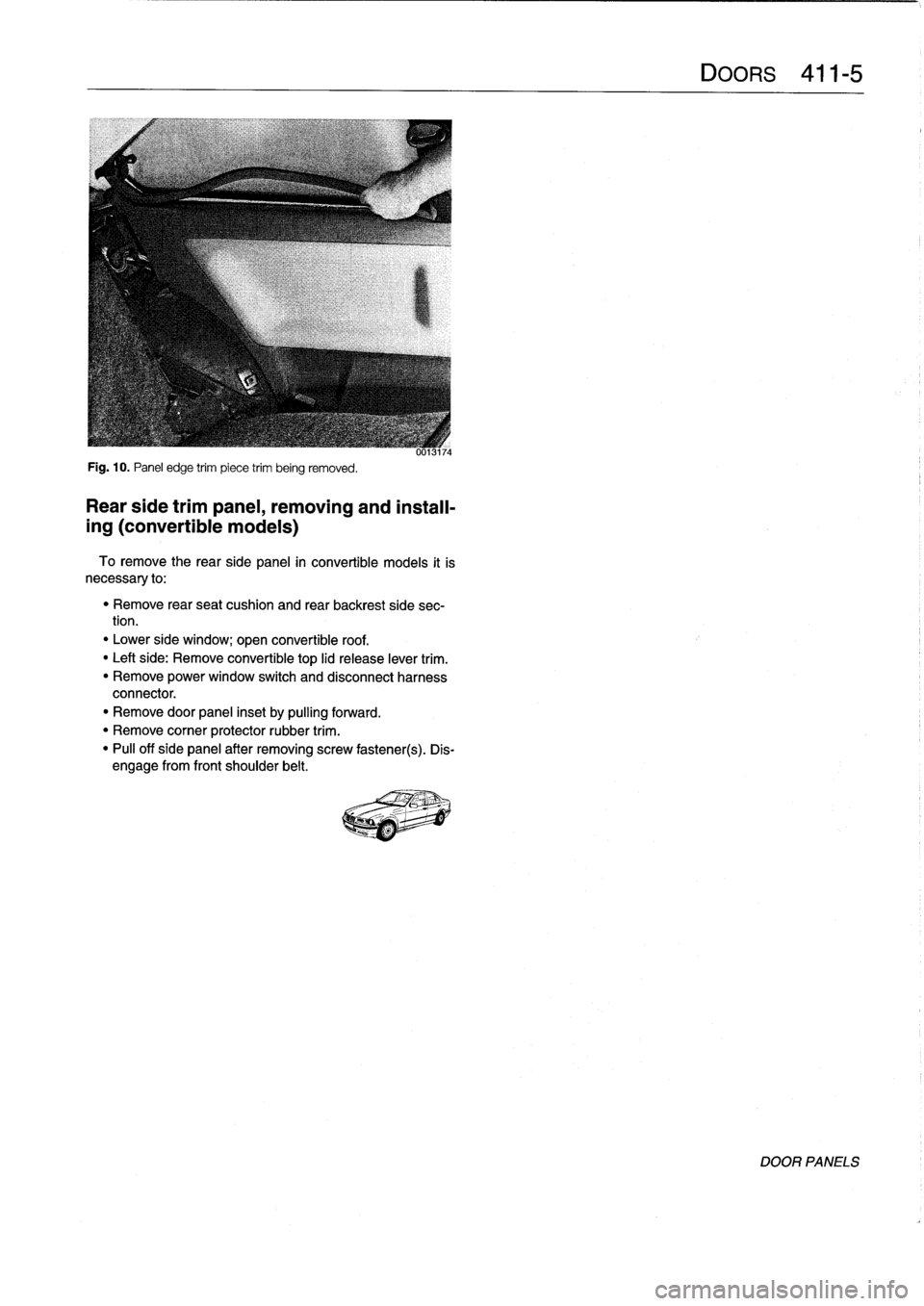
Fig
.
10
.
Panel
edge
trim
piece
trim
being
removed
.
Rear
side
trimpanel,
removing
and
install-
ing
(convertible
models)
To
remove
the
rearside
panel
in
convertible
models
it
is
necessary
to
:
"
Remove
rear
seat
cushion
and
rear
backrest
side
sec-
tion
.
"
Lower
side
window
;
open
convertible
roof
.
"
Leftside
:
Remove
convertible
top
lid
release
lever
trim
.
"
Remove
power
window
switch
and
disconnect
harness
connector
.
"
Remove
door
panel
inset
by
pulling
forward
.
"
Remove
corner
protector
rubber
trim
.
"
Pull
off
side
panel
after
removing
screw
fastener(s)
.
Dis-
engage
from
front
shoulder
belt
.
Page 321 of 759
GENERAL
This
repair
group
covers
trunk
lid
removal
and
installation
.
Also
inciuded
here
arereplacement
procedures
for
the
gas-
charged
support
struts
that
hold
the
trunk
lid
in
the
up
position
.
NOTE
-
The
body
ís
painted
at
the
factory
after
assembly
.
Re-
alignment
of
body
panels
may
expose
unpainted
metal
.
Paint
all
exposed
metal
once
the
work
is
complete
.
TRUNK
LID
Trunk
lid,
removing
and
installing
1
.
Raise
trunk
lid
.
Open
tool
kit
and
remove
screws
at-
taching
tool
kit
lo
trunk
lid
.
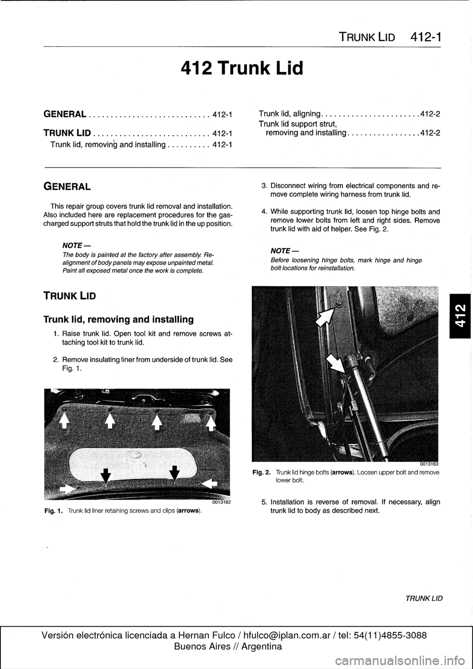
2
.
Remove
insulating
liner
from
underside
of
trunk
lid
.
See
Fig
.
1
.
412
Trunk
Lid
TRUNK
LID
412-1
GENERAL
............
.
...
.
.....
.
...
.
.
412-1
Trunk
lid,
aligning
.
.
.
.
.
.....
.
...
.
.
.
.
.
.
.
..
412-2
Trunk
lid
support
strut,
TRUNK
LID
.
.
.
............
.
.
.
...
.
.
.
.
.
.
412-1
removing
and
installing
..
.
.
.
.
.
.
.
.
.
...
.
.
.
412-2
Trunk
lid,
removinb
and
installing
......
.
.
.
.
412-1
3
.
Disconnect
wiring
from
electrical
components
and
re-
move
complete
wiring
harness
from
trunk
lid
.
4
.
While
supporting
trunk
lid,
loosen
top
hinge
bolts
and
remove
lower
bolts
from
left
and
right
sides
.
Remove
trunk
lid
with`aid
of
helper
.
See
Fig
.
2
.
NOTE-
Before
loosening
hinge
bolts,
mark
hinge
and
hinge
bolt
locations
for
reínstallation
.
0013163
Fig
.
2
.
Trunk
lid
hinge
bolts
(arrows)
.
Loosen
upper
bolt
and
remove
lower
bolt
.
0013162
5
.
Installation
is
reverse
of
removal
.
If
necessary,
align
Fig
.
1
.
Trunk
lid
liner
retaining
screws
and
clips
(arrows)
.
trunk
lid
to
body
as
described
next
.
TRUNK
LID
Page 323 of 759
GENERAL
.
.
.
.
.
.
.
.
.
...
.
..
.
...
.
.........
510-1
Front
bumper
impact
absorber,
replacing
....
510-4
Rear
bumper,
removing
and
installing
.....
.510-4
OUTSIDE
REAR
VIEW
MIRRORS
.
...
.
.....
510-1
Rear
bumper
impact
absorber,
replacing
...
.
510-6
Outside
mirrorglass,
replacing
.
.
.........
510-1
Bumper
height,
adjusting
...
.
...
.
...
.
.
.
.
.
510-6
Outside
mirror
housing,
removing
and
installing
....
.
.....
.
.
.
.
.
.
510-1
EXTERIOR
TRIM
...
.
.
.
.
.
.
.
.
.
.
.
...
.
.
.
.
.
510-6
Outside
mirror,
removing
and
installing
.
.
.
.
.
510-2
BMW
embiem,
removing
and
installing
.
.
.
.
.
.
510-7
Body
side
molding,
replacing
.
.
.
.
.
.
.
.
.
.
.
.
.
510-7
BUMPERS
.
.
.
.
.
....
.
.....
.
.....
.
.
.
.
.
.
510-3
Radiator
grille,
removing
and
installing
.
.
.
.
.
.510-7
Front
bumper,
removing
and
installing
.
.
.
.
.
.
510-3
Front
panel,
removing
and
installing
...
.
.
.
.
.
510-7
GENERAL
510
Exterior
Trim,
Bumpers
This
repair
group
includes
repair
information
for
the
outside
rear
view
mirror,
front
and
rear
bumpers,
and
the
easily
re-
movable
exterior
trim
parts
.
OUTSIDE
REAR
VIEW
MIRRORS
The
remove
controlled
mirrors
come
in
two
styles
:
heated
and
unheated
.
Many
of
the
mirror
components
are
separately
available
from
an
authorized
BMW
dealer,
including
the
glass
and
outside
plastic
housing
.
Outside
mirror
glass,
replacing
CAUTION-
Mirror
shouldbe
ator
above
room
temperature
before
removal
.
Otherwise,
small
plastic
parts
or
glass
will
break
.
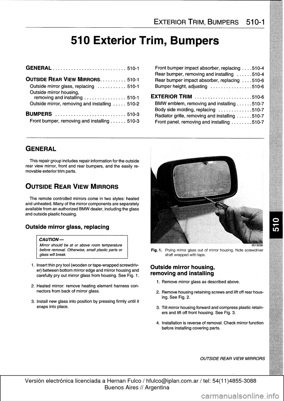
1
.
Insert
thin
pry
tool
(wooden
or
tape-wrapped
screwdriv-
er)
between
bottom
mirror
edge
and
mirror
housing
and
carefully
pry
out
mirror
glass
from
housing
.
See
Fig
.
1
.
2
.
Heated
mirror
:
remove
heating
element
harness
con-
nectors
from
back
of
mirror
glass
.
3
.
Install
new
glass
into
position
by
pressing
firmly
until
it
snaps
into
place
.
EXTERIOR
TRIM,
BUMPERS
510-1
00130
..
Fig
.1
.
Prying
mirror
glass
out
of
mirror
housing
.
Note
screwdriver
shaft
wrapped
with
tape
.
Outside
mirror
housing,
removing
and
installing
1
.
Remove
mirror
glass
as
described
above
.
2
.
Remove
housing
retaining
screws
and
lift
off
rear
hous-
ing
.
See
Fig
.
2
.
3
.
Tilt
mirror
housing
forward
and
compress
plastic
retain-
ers
and
lift
off
front
housing
.
See
Fig
.
3
.
4
.
Installation
is
reverse
of
removal
.
Check
mirror
function
before
installing
covering
parts
.
OUTSIDE
REAR
VIEW
MIRRORS
Page 324 of 759
510-2
EXTERIOR
TRIIVI,
BUMPERS
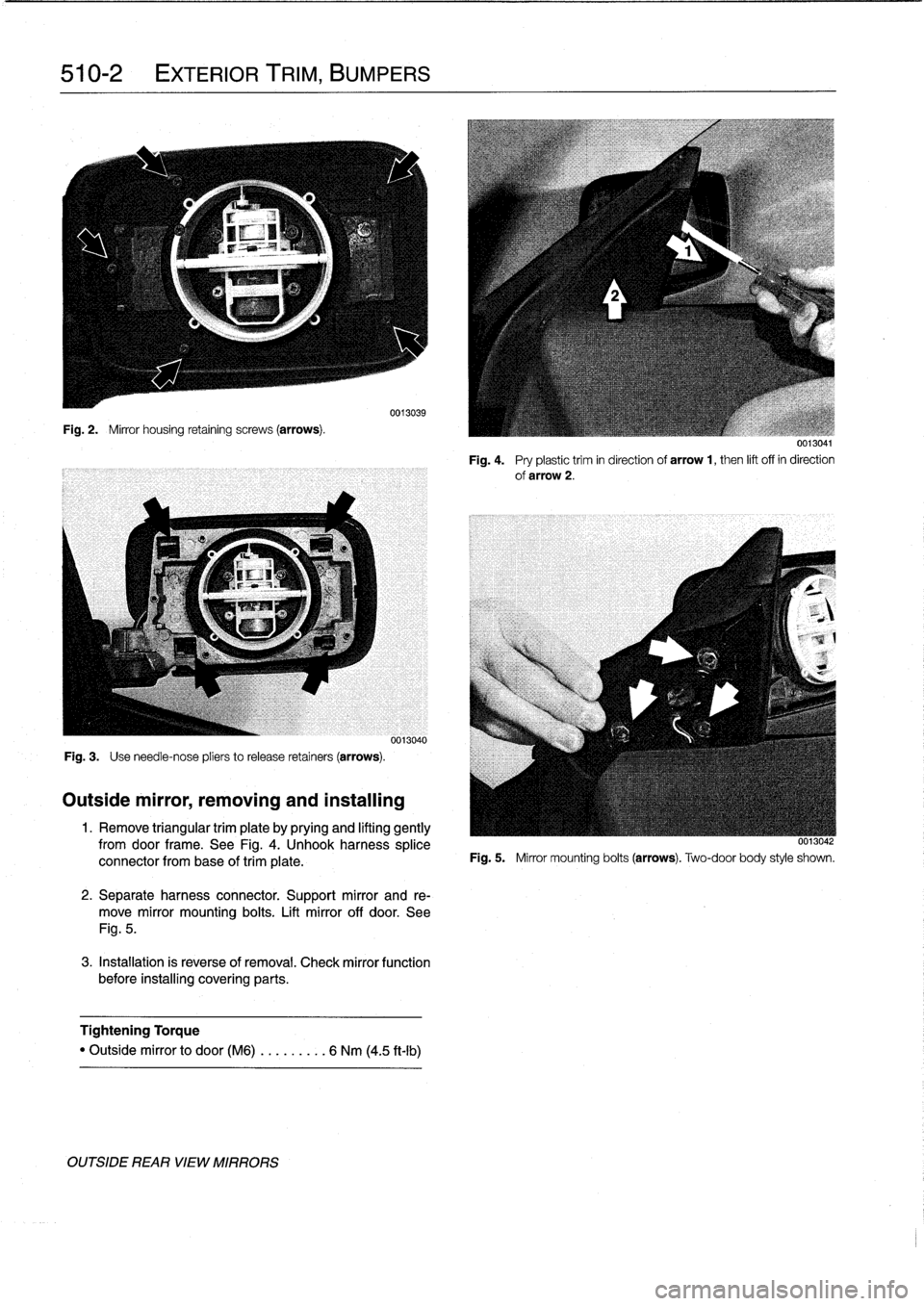
Fig
.
2
.
Mirror
housing
retaining
screws
(arrows)
.
Fig
.
3
.
Use
need1e-nose
pliers
to
release
retainers
(arrows)
.
Outside
mirror,
removing
and
installing
0013039
0013040
1
.
Remove
triangular
trim
plate
by
prying
and
lifting
gently
fromdoor
frame
.
See
Fig
.
4
.
Unhook
harness
splice
connector
from
base
of
trim
píate
.
2
.
Separate
harness
connector
.
Support
mirror
and
re-
move
mirror
mounting
bolts
.
Lift
mirror
off
door
.
See
Fig
.
5
.
3
.
Installation
is
reverse
of
removal
.
Check
mirror
function
before
installing
covering
parts
.
Tightening
Torque
"
Outside
mirror
to
door(M6)
..
.
..
.
..
.
6
Nm
(4
.5
ft-Ib)
OUTSIDE
REAR
VIEW
MIRRORS
0013041
Fig
.
4
.
Pry
plastictrim
in
direction
of
arrow
1,
then
lift
off
in
direction
of
arrow
2
.
0013042
Fig
.
5
.
Mirror
mounting
bolts
(arrows)
.
Two-door
body
style
shown
.
Page 325 of 759
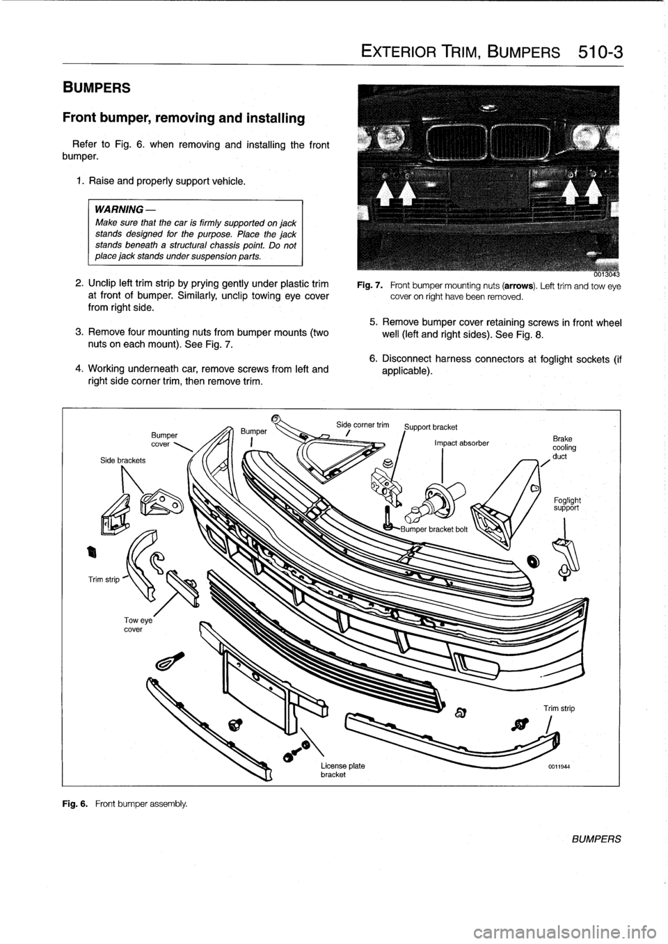
BUMPERS
Front
bumper,
removing
and
installing
Refer
to
Fig
.
6
.
when
removing
and
installing
the
front
bumper
.
1
.
Raise
and
properly
support
vehicle
.
WARNING
-
Make
sure
that
the
car
is
firmly
supportedonjack
stands
designed
for
the
purpose
.
Place
the
jackstands
beneath
a
structural
chassis
point
.
Do
not
place
jack
stands
undersuspension
parts
.
2
.
Unclip
left
trim
strip
by
prying
gently
under
plastic
trim
at
front
of
bumper
.
Similarly,
unclip
towing
eyecoverfrom
right
side
.
5
.
Remove
bumper
cover
retaining
screws
in
front
wheel
3
.
Remove
four
mounting
nuts
from
bumper
mounts
(two
well
(left
and
right
sides)
.
See
Fig
.
8
.
nuts
on
eachmount)
.
See
Fig
.
7
.
4
.
Working
underneath
car,
removescrews
from
left
and
right
side
corner
trim,
then
remove
trim
.
Side
brackets
Bumper
cover
Fig
.
6
.
Front
bumper
assembly
.
EXTERIOR
TRIM,
BUMPERS
510-3
Fig
.
7
.
Front
bumper
mounting
nuts
(arrows)
.
Lefttrim
andtow
eye
cover
on
right
have
been
removed
.
6
.
Disconnect
harness
connectors
at
foglight
sockets
(if
applicable)
.
Side
corner
trim
Support
bracket
Impact
absorber
o
O
Foglight
support
LBumner
bracket
bolt
License
plata
0011944
bracket
BUMPERS
Page 326 of 759
510-4
EXTERIOR
TRIM,
BUMPERS
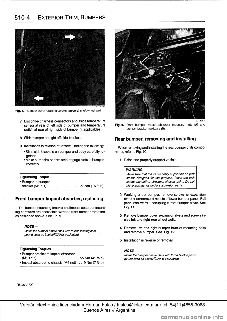
Fig
.
8
.
Bumper
cover
retaining
screws
(arrows)
in
left
wheel
weil
.
7
.
Disconnect
harnessconnectors
at
outside
temperature
0013052
sensor
at
rear
of
left
side
of
bumperand
temperatura
Fig
.
9
.
Front
bumper
impact
absorber
mounting
nuts
(A)
and
switch
at
rear
of
right
side
of
bumper
(if
applicable)
.
bumper
bracket
hardware
(B)
.
8
.
Slide
bumper
straight
off
sida
brackets
.
9
.
Installation
is
reverse
of
removal,
notingthe
following
:
When
removing
and
installing
therear
bumper
or
its
compo-
"
Slide
side
brackets
on
bumper
and
body
carefully
to-
nents,
referto
Fig
.
10
.
gether
.
"
Make
sure
tabs
on
trim
strip
engage
slots
in
bumper
1
.
Raise
and
properly
support
vehicle
.
correctly
.
Tightening
Torque
"
Bumper
to
bumper
bracket
(M8
nut)
............
...
.
.
22
Nm
(16
ft-Ib)
2
.
Working
under
bumper,
remove
screws
or
expansion
Front
bumper
impact
absorber,replacing
rivetsat
corners
and
middle
of
lower
bumper
panel
.
Pull
panel
backward,
uncoupling
it
from
bumper
cover
.
See
Thebumper
mounting
bracket
and
impact
absorber
mount-
Fig
.
11
.
ing
hardware
are
accessible
with
the
Font
bumper
removed,
as
described
above
.
See
Fig
.
9
.
3
.
Remove
bumper
cover
expansion
rivets
and
screws
in-
side
left
and
right
rear
wheel
wells
.
NOTE
-
Install
the
bumper
bracket
boltwith
thread
locking
com-
pound
suchas
Loctite
8
270
or
equivalent
.
Tightening
Torques
"
Bumper
bracket
to
impact
absorber
(M10
nut)
.
..
.
...
.............:.
55
Nm
(41
ft-Ib)
"
Impact
absorber
to
chassis
(M6
nut)
...
9
Nm
(7
ft-Ib)
BUMPERS
Rear
bumper,
removing
and
installing
WARNING
-
Make
sure
that
the
car
is
firmly
supported
on
jack
stands
designad
for
the
purpose
.
Place
the
jack
stands
beneath
a
structural
chassis
point
.
Do
not
place
jack
stands
under
suspension
parts
.
4
.
Remove
left
and
right
bumper
bracket
mounting
bolts
and
remove
bumper
.
See
Fig
.
12
.
5
.
Installation
is
reverse
of
removal
.
NOTE-
Install
the
bumper
bracket
bolt
with
thread
locking
com-
pound
suchas
Loctite®270
or
equivalent
.
Page 332 of 759
512-2
DOOR
WINDOWS
WINDOW
SERVICE,
4-DOOR
MODELS
WARNING
-
When
servicing
the
door
wíndows,
theharness
con-
nector
to
the
window
regulator
shouldalways
be
disconnected
to
prevent
pinching
fingers
in
closing
window
.
NOTE-
If
the
battery
is
disconnected,
the
front
window
regula-
tor
motors
must
be
re-initialized
afterrepairs
are
car-ried
out
.
lf
the
window
motorsare
not
reinitialized,
the
programmed
one-touch
upldown
and
anti-pinchfunc-
tions
will
be
disabled
.
See
Front
door
window,
initial-
izing
.
Front
doorwindow,
removing
and
installing
0013061
(4-door
modeis)
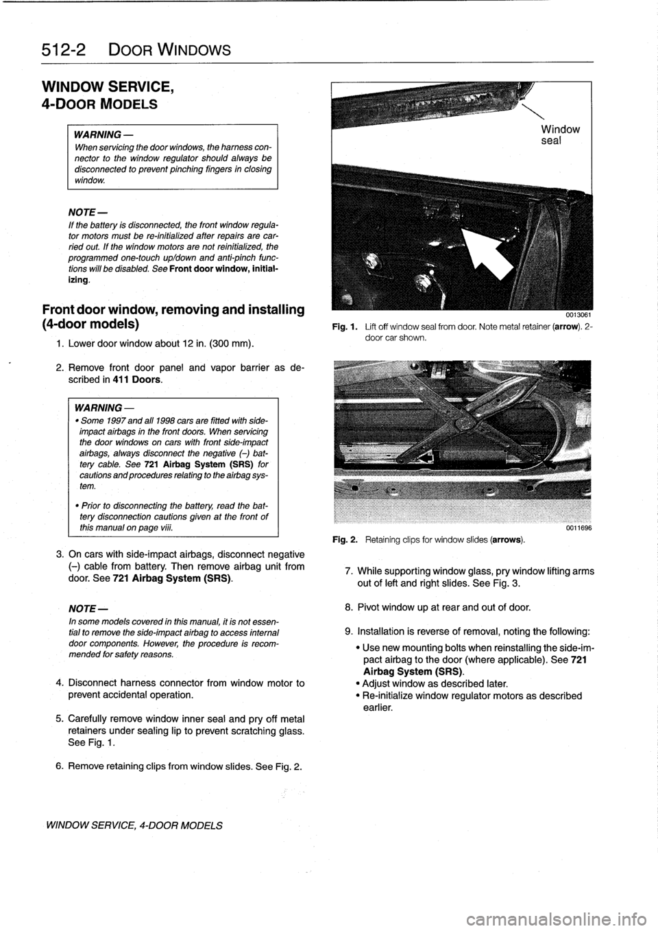
Fig
.1.
Lift
off
window
sea¡
from
door
.
Note
metal
retainer
(arrow)
.
2-
door
car
shown
.
1
.
Lower
door
window
about
12
in
.
(300
mm)
.
2
.
Remove
front
door
panel
and
vapor
barrieras
de-
scribed
in
411
Doors
.
WARNING
-
"
Some
1997
and
all
1998
cars
are
fitted
wlth
side-
impact
airbags
in
the
front
doors
.
When
servicing
the
door
wíndows
on
cars
with
front
side-impact
airbags,
always
disconnect
the
negative
()
bat-
tery
cable
.
See
721Airbag
System
(SRS)
for
cautions
and
procedures
relating
to
theairbag
sys-
tem
.
"
Prior
to
disconnectiog
the
battery,
read
the
bat-
tery
disconnection
cautions
given
at
the
front
of
this
manual
on
page
vi¡¡
.
3
.
On
cars
with
side-impact
airbags,
disconnect
negative
(-)
cable
from
battery
.
Then
remove
airbag
unit
fromdoor
.
See
721
Airbag
System
(SRS)
.
5
.
Carefully
remove
window
innersea¡
and
pry
off
metal
retainers
under
sealing
lip
to
prevent
scratchingglass
.
See
Fig
.
1
.
6
.
Remove
retaining
clips
from
window
slides
.
See
Fig
.
2
.
WINDOW
SERVICE,
4-DOOR
MODELS
Fig
.
2
.
Retaining
clipsfor
window
slides
(arrows)
.
0011696
7
.
While
supporting
window
glass,
pry
window
lifting
arms
out
of
left
and
right
slides
.
See
Fig
.
3
.
NOTE-
8
.
Pivot
window
up
at
rear
and
out
of
door
.
In
some
modeis
covered
inthis
manual,
it
is
not
essen-
tial
to
remove
the
side-impact
airbag
to
access
internal
9
.
Installation
is
reverse
of
removal,
notingthe
following
:
door
components
.
However,
the
procedure
is
recom-
"
Usenew
mounting
bolts
when
reinstalling
the
side-im-
mended
forsafety
reasons
.
pactairbag
to
the
door(where
applicable)
.
See
721
Airbag
System
(SRS)
.
4
.
Disconnect
harness
connector
from
window
motor
to
"
Adjust
window
as
described
later
.
prevent
accidental
operation
.
"
Re-initialize
window
regulator
motorsas
described
earlier
.
Page 334 of 759
512-
4
DOOR
WINDOWS
7
.
Push
regulator
stop
tightly
against
window
regulator
4
.
Lower
door
window
about
12
in
.
(300
mm)
.
Remove
sector
and
tighten
nut
.
window
lifting
arm
retaining
clip
from
window
slide
.
Re-
o
Check
for
tight,
even
fit
at
top
of
window
frame
.
fer
to
Fig
.
2
.
"
If
necessary,temporarily
reconnect
negative
(-)
cable
to
battery
and
raise
window
so
it
is
pressing
uniformly
WARNING-
against
toprubber
sea¡
before
final
tightening
.
Once
the
window
is
lowered,
dísconnect
harness
connector
from
power
window
motor
to
prevent
ac-
8
.
Reinitialize
front
window
motorsas
described
earlier
.
cidental
operation
of
the
window
.
Tightening
Torques
"
Regulator
stop
to
window
regulator
....
9
Nm
(7
ft-Ib)
"
Window
regulator
bracket
to
door
.....
9
Nm
(7
ft-Ib)
Rear
door
window,
removing
and
installing
(4-door
models)
1
.
Remove
rear
door
panel
and
vapor
barrier
.
See
411
7
.
Remove
window
glass
from
above
.
Doors
.
2
.
Pul¡
out
rubber
guide
at
front
of
window
frame
.
Remove
three
screws
and
pul¡
off
exteriortrim
cover
.
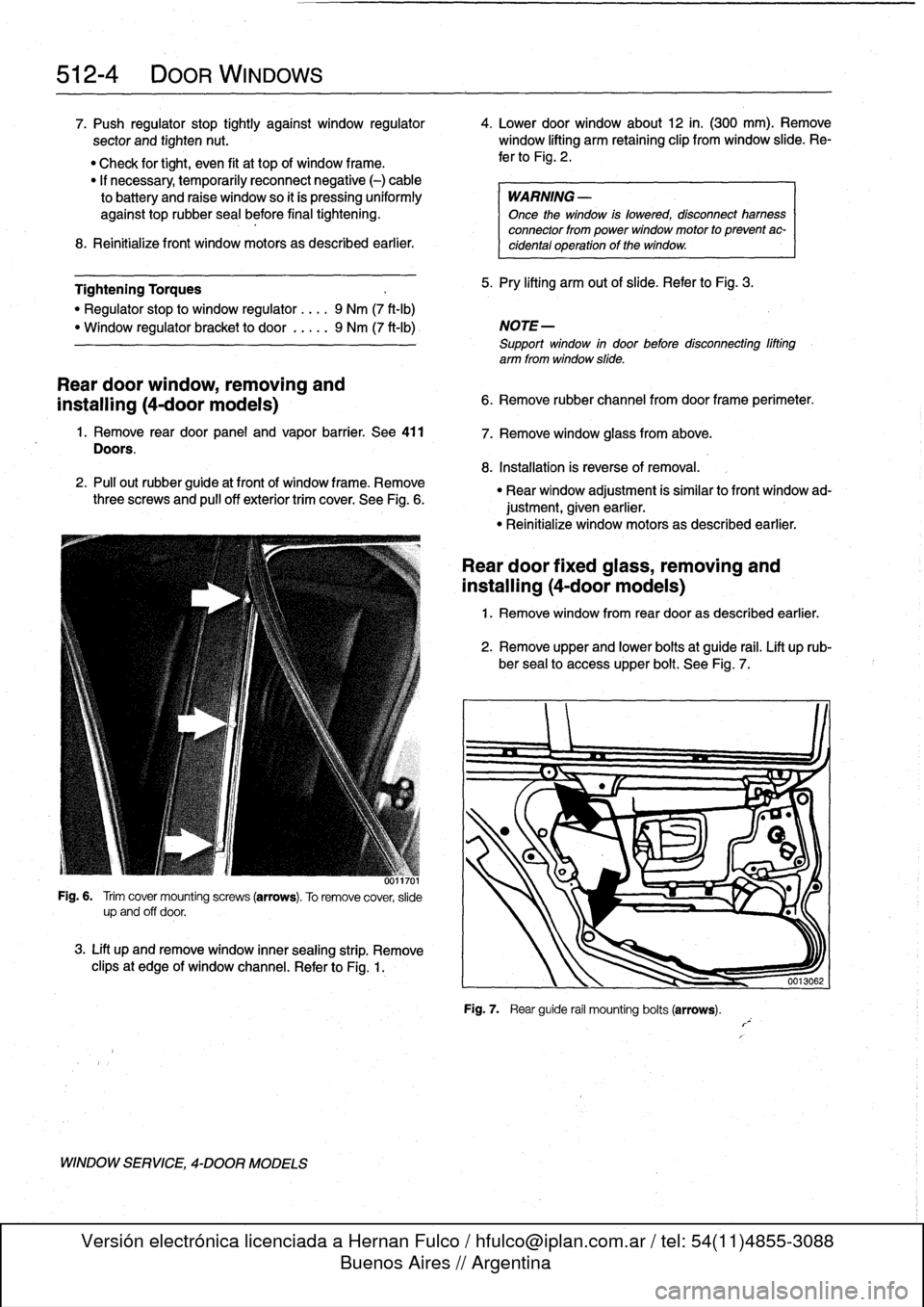
See
Fig
.
6
.
UJ117U1
Fig
.
6
.
Trim
covermounting
screws
(arrows)
.
To
remove
cover,
slide
upand
off
door
.
3
.
Lift
up
andremovewindow
inner
sealing
strip
.
Remove
clipsat
edge
of
window
channel
.
Refer
to
Fig
.
1
.
WINDOW
SERVICE,
4-DOOR
MODELS
5
.
Pry
lifting
arm
out
of
slide
.
Refer
to
Fig
.
3
.
NOTE
-
Support
window
in
door
before
disconnecting
lifting
arm
from
window
slide
.
6
.
Remove
rubber
channelfromdoorframe
perimeter
.
8
.
Installation
is
reverse
of
removal
.
"
Rear
window
adjustment
is
similar
to
front
window
ad-
justment,given
earlier
.
"
Reinitialize
window
motorsas
described
earlier
.
Rear
door
fixed
glass,
removing
and
installing
(4-door
models)
1
.
Remove
window
from
rear
dooras
described
earlier
.
2
.
Remove
upper
and
lower
bolts
at
guide
rail
.
Lift
up
rub-
ber
sea¡
to
accessupper
bolt
.
See
Fig
.
7
.
Fig
.
7
.
Rear
guide
rail
mounting
bolts
(arrows)
.
Page 346 of 759
513-2
INTERIOR
TRim
DASHBOARD
Dashboard
removal
is
a
complex
operation,
involving
dis-
connection
and
dismantling
of
a
number
of
electrical
and
dash
structural
components
.
The
BMW
E36
is
equipped
with
SRS
airbags
mounted
in
the
steering
wheel,
in
the
dashboard
(1994
and
later)
on
the
passenger
side,
and
in
the
front
doors(1997
and
later)
.
Air-
bags
units
are
pyrotechnic
devices
and
should
be
treated
with
extreme
caution
.
Improper
handling
of
the
airbags
could
cause
serious
injury
.
WARNING
-
"
The
BMW
Supplemental
Restraint
System
(SRS)
is
complex
and
special
precautions
must
be
ob-
served
when
servicing
.
Serious
injury
may
result
if
system
service
is
attempted
by
persons
unfa-
miliar
with
the
BMW
SRS
and
its
approved
ser-vice
procedures
.
BMW
specifies
that
all
inspection
and
service
shouldbe
performed
byan
authorized
BMW
dealer
.
"
Beforeperforming
any
work
involving
the
steering
wheel
or
interior
trim
in
the
vicinity
of
the
airbags,
disconnect
the
negative
()
battery
cable
.
See
721
Airbag
System
(SRS)
.
"
SRS
contains
aback-up
power
supply
within
the
SRS
control
module
.
A
10
minute
díscharge
peri-
od
should
be
allowed
after
the
battery
cable
has
been
disconnected
.
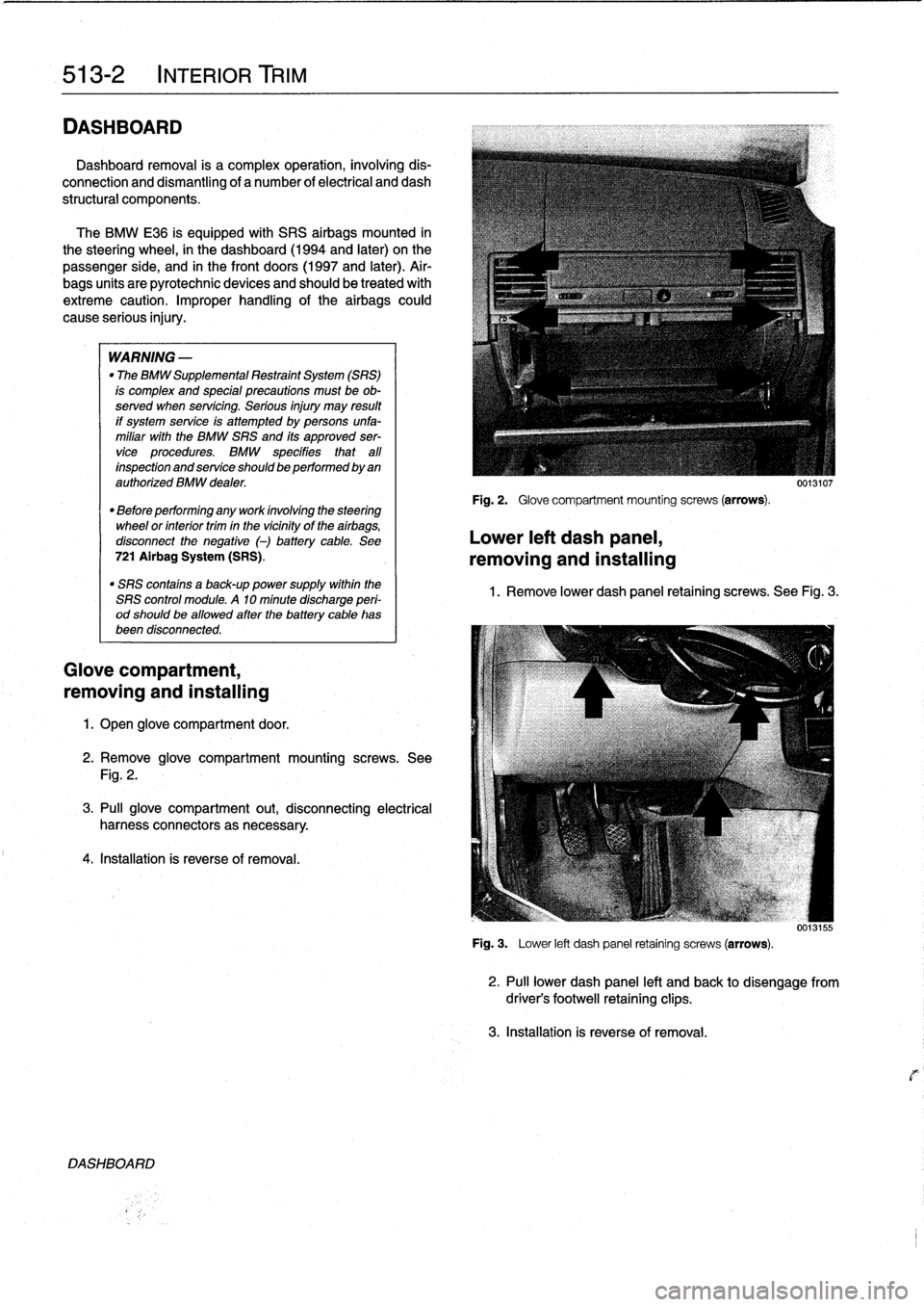
Glove
compartment,
removing
and
installing
1.
Open
glove
compartment
door
.
2
.
Remove
glove
compartment
mounting
screws
.
See
Fig
.
2
.
3
.
Pull
glove
compartment
out,
disconnecting
electrical
harness
connectors
as
necessary
.
4
.
Installation
is
reverse
of
removal
.
DASH80ARD
Fig
.
2
.
Glove
compartment
mounting
screws
(arrows)
.
Lower
left
dash
panel,
removing
and
installing
0013107
1
.
Remove
lower
dash
panel
retaining
screws
.
See
Fig
.
3
.
0013155
Fig
.
3
.
Lower
left
dash
panel
retaining
screws
(arrows)
.
2
.
Pull
lower
dash
panel
left
and
back
to
disengagefrom
driver's
footwell
retaining
clips
.
3
.
Installation
is
reverse
of
removal
.
Page 348 of 759
513-
4
INTERIOR
TRIM
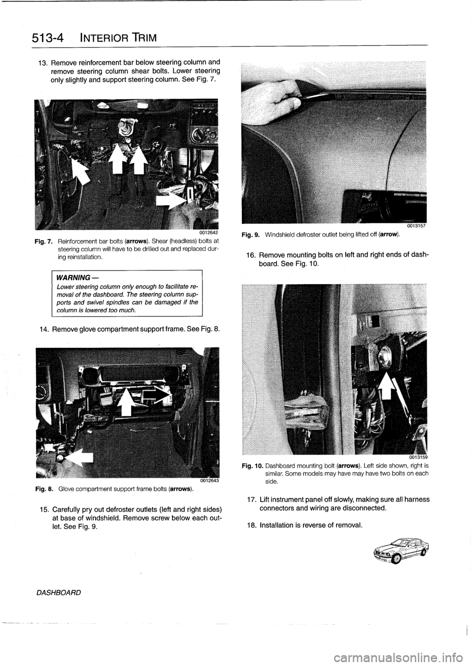
13
.
Remove
reinforcement
bar
below
steering
column
and
remove
steering
column
shear
bolts
.
Lower
steering
only
slightly
and
support
steering
column
.
See
Fig
.
7
.
WARNING
-
Lower
steering
column
only
enough
to
facilitate
re-
moval
of
the
dashboard
.
The
steering
column
sup-
ports
and
swivel
spindles
canbe
damaged
if
the
column
is
lowered
too
much
.
14
.
Remove
glove
compartment
support
frame
.See
Fig
.
8
.
0012643
Fig
.
8
.
Glove
compartment
support
frame
bolts
(arrows)
.
DASHBOARD
0013157
Fig
.
9
.
Windshield
defroster
outlet
being
lifted
off
(arrow)
.
Fig
.
7
.
Reinforcementbar
bolts
(arrows)
.
Shear
(headless)
bolts
at
steering
column
will
have
to
be
drilled
out
and
replaceddur-
ing
reinstallation
.
16
.
Remove
mounting
bolts
on
left
and
right
ends
of
dash-
board
.
See
Fig
.
10
.
Fig
.
10
.
Dashboard
mounting
bolt
(arrows)
.
Left
side
shown,
right
is
similar
.
Some
models
may
have
may
have
two
bolts
oneach
side
.
17
.
Lift
instrument
panel
off
slowly,
making
sure
all
harness
15
.
Carefullypryout
defroster
outlets
(left
and
right
sides)
connectors
and
wiring
are
disconnected
.
a
t
base
of
windshield
.
Remove
screwbelow
each
out-
let
.
See
Fig
.
9
.
18
.
Installation
is
reverse
of
removal
.