ing harness BMW M3 1995 E36 Service Manual
[x] Cancel search | Manufacturer: BMW, Model Year: 1995, Model line: M3, Model: BMW M3 1995 E36Pages: 759
Page 165 of 759
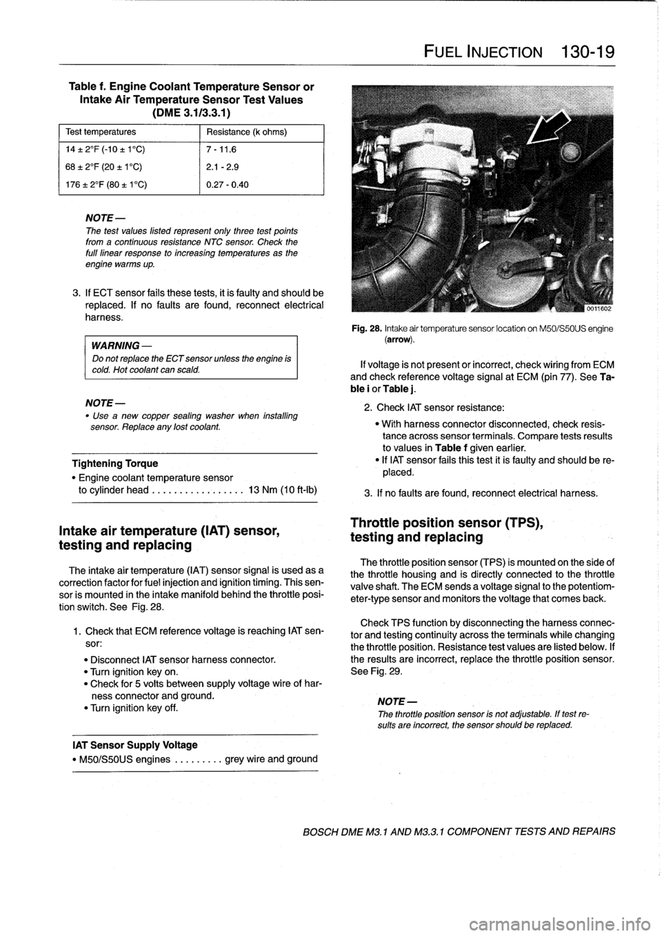
Table
f
.
Engine
Coolant
TemperatureSensor
or
Intake
Air
TemperatureSensor
Test
Values
(DME
3
.113
.3
.1)
Test
temperatures
Resistance
(k
ohms)
14±
2°F
(-10
±
1'C)
7-11
.6
68±
2°F
(20
±
1'C)
2
.1
-2
.9
17612°F
(80
t
V
C)
0
.27-0
.40
NOTE
The
test
values
listed
represent
only
three
test
points
from
a
continuous
resistance
NTC
sensor
.
Check
the
full
linear
response
to
increasing
temperatures
as
the
engine
warms
up
.
3
.
If
ECT
sensor
fails
these
tests,
it
is
faulty
and
should
be
replaced
.
If
no
faults
are
found,
reconnect
electrical
harness
.
WARNING
-
Do
not
replace
the
ECT
sensor
unless
the
engine
is
cold
.
Hot
coolant
can
scald
.
NOTE-
Use
"
a
new
copper
sealing
washer
when
installing
sensor
.
Replace
any
lost
coolant
.
Tightening
Torque
"
Engine
coolant
temperature
sensor
to
cylinder
head
.........
..
.
..
...
13
Nm
(10
ft-lb)
Intake
air
temperature
(IAT)
sensor,
testing
and
replacing
The
intake
air
temperature
(IAT)
sensor
signal
is
usedasa
correction
factor
for
fuel
injection
and
ignition
timing
.
Thissen-
sor
is
mounted
in
the
intake
manifold
behind
the
throttle
posi-
tion
switch
.
See
Fig
.
28
.
Check
TPS
function
by
disconnecting
theharnessconnec-
1
.
Check
that
ECM
reference
voltage
is
reaching
IAT
sen-
tor
and
testing
continuity
across
the
terminalswhile
changing
sor
:
the
throttle
position
.
Resistance
test
values
are
listed
below
.
If
"
Disconnect
IAT
sensor
harness
connector
.
the
resuits
are
incorrect,
replace
the
throttle
position
sensor
.
"
Turn
ignition
keyon
.
See
Fig
.
29
.
"
Check
for
5
volts
between
supply
voltage
wire
of
har-
ness
connector
and
ground
.
NOTE-
"
Turn
ignition
key
off
.
The
throttle
position
sensor
is
not
adjustable
.
If
test
re-
sults
are
incorrect,
the
sensor
should
be
replaced
.
IAT
Sensor
Supply
Voltage
"
M50/S50US
engines
.
........
grey
wire
and
ground
FUEL
INJECTION
130-19
Fig
.
28
.
Intake
air
temperature
sensor
location
on
M50/S50US
engine
(arrow)
.
If
voltage
is
not
present
or
incorrect,
check
wiring
from
ECM
and
check
reference
voltage
signal
at
ECM
(pin
77)
.
See
Ta-
ble
i
or
Table
j
.
2
.
Check
IAT
sensor
resistance
:
"
With
harness
connector
disconnected,
check
resis-
tance
acrosssensor
terminals
.
Compare
tests
resuits
to
values
in
Table
f
given
earlier
.
"
If
IAT
sensor
fafs
thistest
it
is
faulty
and
should
be
re-
placed
.
3
.
If
no
faults
are
found,
reconnect
electrical
harness
.
Throttle
position
sensor
(TPS),
testing
and
replacing
The
throttle
position
sensor
(TPS)
is
mounted
on
the
side
of
the
throttle
housing
and
is
directly
connected
to
the
throttle
valve
shaft
.
The
ECM
sends
a
voltage
signal
to
the
potentiom-
eter-type
sensor
and
monitors
the
voltage
that
comes
back
.
BOSCH
DME
M3
.
1
AND
M32
.1
COMPONENT
TESTS
AND
REPAIRS
Page 166 of 759
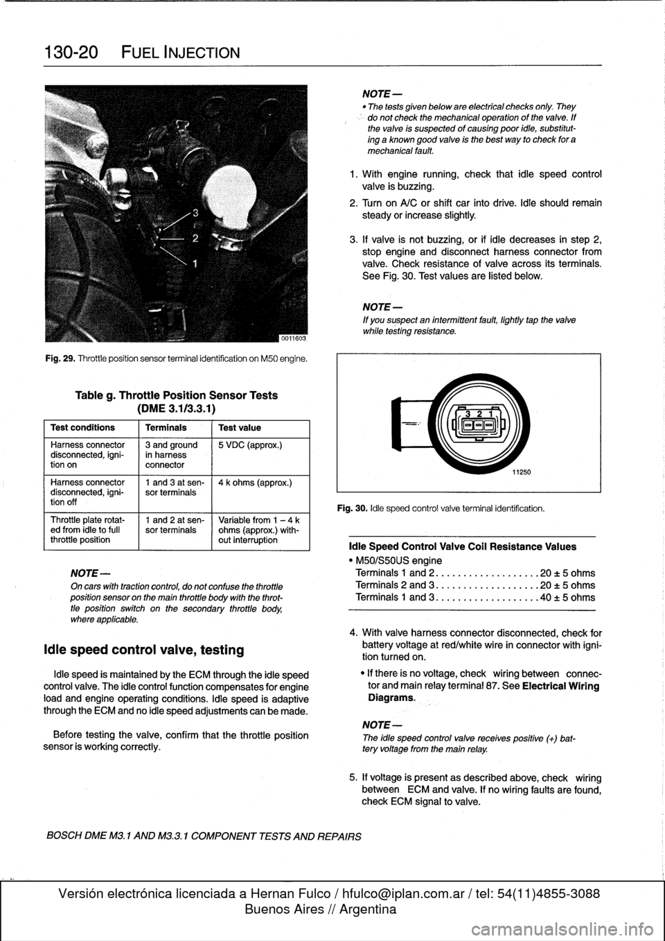
130-20
FUEL
INJECTION
Fig
.
29
.
Throttleposition
sensor
terminal
identification
on
M50
engine
.
Tableg
.
Throttle
Position
Sensor
Tests
(DME3
.113
.3
.1)
Test
conditions
I
Terminals
I
Testvalue
Harness
connector
13
andground
15
VDC
(approx
.)
disconnected,
igni-
in
harness
tion
on
connector
Harness
connector
1
and3
at
sen-
14
k
ohms
(approx
.)
disconnected,
igni-
sor
terminals
tion
off
Throttle
plate
rotat-
1
and
2
at
sen-
Variable
from
1
-
4ked
from
¡dieto
full
sor
terminals
ohms
(approx
.)
with-
throttle
position
out
interruption
¡die
Speed
Control
Valve
Coil
Resistance
Values
"
M50/S50US
engine
NOTE-
Terminals
1
and
2
..
.
................
20
t
5
ohms
On
cars
with
tractioncontrol,
do
not
confuse
the
throttle
Terminals
2
and
3
...................
20
t5
ohms
position
sensor
on
the
main
throttle
body
with
the
throt-
Terminals
1
and
3
..
.
..
:
............
.40
t
5
ohms
tle
positionswitch
on
the
secondary
throttle
body,
where
applicable
.
¡die
speed
control
valve,
testing
¡die
speed
is
maintained
by
the
ECM
through
the
¡die
speed
control
valve
.
The
¡die
controlfunction
compensates
for
engine
load
and
engine
operating
conditions
.
¡die
speed
is
adaptive
through
the
ECM
and
no
¡die
speed
adjustments
can
be
made
.
NOTE-
Before
testing
the
valve,
confirm
that
the
throttle
position
The
idle
speed
controlvalve
receives
positive
(+)
bat-
sensor
is
working
correctly
.
tery
voltage
from
the
main
relay
.
BOSCH
DME
M3
.
1
AND
M3
.3
.1
COMPONENT
TESTS
AND
REPAIRS
NOTE-
"
The
tests
given
below
are
electrical
checks
only
.
They
do
not
check
the
mechanical
operation
of
the
valve
.
If
the
valve
is
suspected
of
causing
poor
idie,
substitut-
ing
a
known
good
valve
is
the
best
way
to
check
for
a
mechanical
fault
.
1
.
With
engine
running,
check
that
¡die
speed
control
valve
is
buzzing
.
2
.
Turn
on
A/C
or
shift
car
finto
drive
.
¡die
should
remain
steady
orincrease
slightly
.
3
.
If
valve
is
not
buzzing,or
if
¡die
decreases
in
step
2,
stop
engine
and
disconnect
harness
connector
from
valve
.
Check
resistance
of
valve
across
its
terminals
.
See
Fig
.
30
.
Test
values
are
listed
below
.
NOTE
-
If
you
suspect
an
intermittent
fault,
lightly
tapthe
valve
while
testing
resistance
.
11250
Fig
.
30
.
¡die
speed
control
valve
terminal
identification
.
4
.
With
valve
harnessconnector
disconnected,
check
for
battery
voltage
at
red/white
wire
in
connector
with
igni-
tion
tumed
on
.
"
If
there
is
no
voltage,
check
wiring
between
connec-
tor
and
main
relayterminal
87
.
See
Electrical
Wiring
Diagrams
.
5
.
If
voltage
is
presentas
described
above,
check
wiring
between
ECM
and
valve
.
If
no
wiring
faults
are
found,
check
ECM
signal
to
valve
.
Page 168 of 759
130-
2
2
FUEL
INJECTION
Mass
air
flow
sensor,
replacing
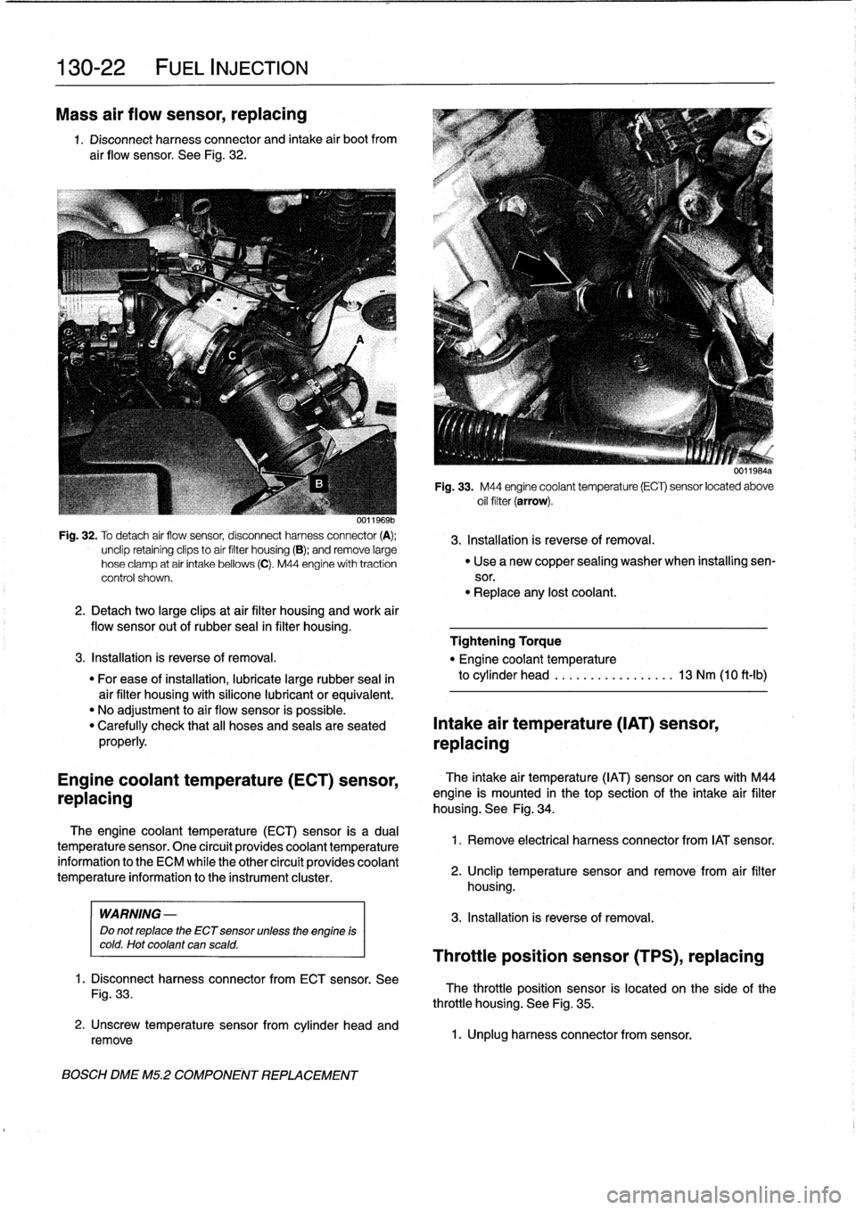
1
.
Disconnect
harness
connector
and
intake
air
bootfrom
air
flow
sensor
.
See
Fig
.
32
.
Fig
.
32
.
To
detach
air
flow
sensor,
disconnect
harness
connector
(A)
;
3
.
Installation
is
reverse
of
removal
.
unclip
retainíng
clips
to
aír
filter
housing
(B)
;
andremove
large
hose
clamp
at
air
intake
bellows
(C)
.
M44
engine
with
traction
"
Use
a
new
copper
sealing
washer
when
installing
sen-
control
shown
.
sor
.
"
Replace
any
lost
coolant
.
2
.
Detachtwo
large
clipsat
air
filter
housing
and
work
air
flow
sensor
out
of
rubber
seal
in
filter
housing
.
Tightening
Torque
3
.
Installation
is
reverse
of
removal
.
"
Engine
coolant
temperature
"
For
ease
of
installation,
lubricate
large
rubber
seal
in
to
cylinder
head
.............
.
..
.
13
Nm
(10
ft-Ib)
air
filter
housing
with
silicone
lubricant
or
equivalent
.
"
No
adjustment
to
air
flow
sensor
is
possible
.
"
Carefully
check
that
all
hoses
and
seals
are
seated
Intake
air
temperature
(IAT)
sensor,
properly
.
replacing
Engine
coolant
temperature
(ECT)
sensor,
replacing
The
engine
coolant
temperature
(ECT)sensor
is
a
dual
temperature
sensor
.
One
circuít
provides
coolant
temperature
information
to
the
ECM
while
the
other
circuít
provides
coolant
temperature
information
to
the
instrument
cluster
.
WARNING
-
Do
not
replace
the
ECT
sensor
unless
the
engine
is
cold
.
Hot
coolant
can
scald
.
1
.
Disconnect
harness
connector
from
ECT
sensor
.
See
Fig
.
33
.
2
.
Unscrew
temperature
sensorfrom
cylinder
head
and
remove
BOSCH
DME
M5
.2
COMPONENT
REPLACEMENT
U1111
bis4a
Fig
.
33
.
M44
engine
coolant
temperature
(ECT)
sensor
located
above
oil
filter
(arrow)
.
The
intake
air
temperature
(IAT)
sensoron
cars
with
M44
engine
is
mounted
in
thetop
section
of
the
intake
air
filter
housing
.
See
Fig
.
34
.
1
.
Remove
electrical
harness
connector
from
IAT
sensor
.
2
.
Unclip
temperature
sensor
and
remove
from
air
filter
housing
.
3
.
Installation
is
reverse
of
removal
.
Throttle
position
sensor
(TPS),
replacing
The
throttle
position
sensor
is
located
on
the
side
of
the
throttle
housing
.
See
Fig
.
35
.
1
.
Unplug
harness
connector
from
sensor
.
Page 169 of 759
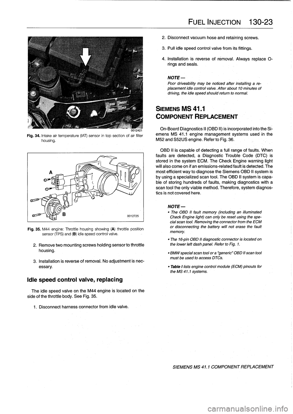
001ía4
i
Fig
.
34
.
Intake
air
temperature
(IAT)
sensor
in
top
section
of
air
filter
housing
.
¡die
speed
control
valve,
replacing
side
of
the
throttle
body
.
See
Fig
.
35
.
1
.
Disconnect
harness
connector
from
¡die
valve
.
0012725
Fig
.
35
.
M44
engine
:
Throttle
housing
showing
(A)
throttle
position
sensor
(fPS)
and
(B)
¡die
speed
control
valve
.
2
.
Remove
twomountingscrews
holding
sensor
to
throttle
housing
.
The
¡die
speed
valve
on
the
M44
engine
is
located
on
the
FUEL
INJECTION
130-23
2
.
Disconnect
vacuum
hose
and
retaining
screws
.
3
.
Pull
¡die
speed
control
valve
from
its
fittings
.
4
.
Installation
is
reverse
of
rémoval
.
Always
replace
0-
rings
and
seals
.
NOTE
Poor
driveability
may
be
notíced
after
installing
a
re-
placement
¡dio
control
valve
.
After
about10
minutes
of
driving,
the
idie
speed
should
retum
to
normal
.
SIEMENS
MS
41
.1
COMPONENT
REPLACEMENT
On-Board
Diagnostics
II
(OBD
II)
is
incorporated
into
the
Si-
emens
MS
41
.1
engine
management
systems
used
in
the
M52
and
S52US
engine
.
Refer
to
Fig
.
36
.
OBD
11
is
capable
of
detecting
a
fui¡
range
offaults
.
When
faults
are
detected,
a
Diagnostic
Trouble
Code
(DTC)
is
stored
in
the
system
ECM
.
The
Check
Engine
warning
light
will
also
come
on
if
an
emissions-related
fault
is
detected
.
The
most
efficient
way
to
diagnose
the
Siemens
OBD
II
system
is
by
using
a
specialized
scan
tool
.
The
OBD
II
system
is
capa-
ble
of
storing
hundreds
of
faults,
making
diagnostics
with
a
scan
tool
the
only
viable
method
.
Therefore,
system
diagnos-
tics
is
not
covered
here
.
NOTE
-
"
The
OBD
11
fault
memory
(including
an
illuminated
Check
Engine
light)
can
only
be
reset
using
the
spe-
cial
scan
tool
.
Removing
the
connector
from
the
ECM
or
disconnecting
the
battery
will
not
erase
the
fault
memory
.
"
The
16-pin
OBD
11
diagnostic
connector
is
located
on
the
lower
left
dash
panel
.
Refer
to
Fig
.
1
.
"
BMW
special
scan
tool
ora
"generic"
OBD
11scan
tool
must
be
used
to
access
DTCs
.
3
.
Installation
is
reverse
of
removal
.
No
adjustment
is
nec
essary
.
"
Table
1
lists
engine
control
module
(ECM)
pinouts
forthe
MS
41
.1
systems
.
SIEMENS
MS
41
.
1
COMPONENT
REPLACEMENT
Page 171 of 759
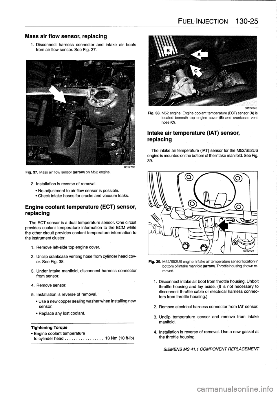
Mass
air
flow
sensor,
replacing
1
.
Disconnect
harness
connector
and
intake
air
boots
from
air
flow
sensor
.
See
Fig
.
37
.
Fig
.
37
.
Mass
air
flow
sensor
(arrow)
on
M52
engine
.
2
.
Installation
is
reverse
of
removal
.
"
No
adjustment
to
aír
flow
sensor
is
possible
.
"
Check
intake
hoses
for
cracks
and
vacuum
leaks
.
Engine
coolant
temperature(ECT)
sensor,
replacing
The
ECT
sensor
is
a
dual
temperature
sensor
.
One
circuit
provides
coolant
temperature
information
to
the
ECM
while
the
other
circuit
provides
coolant
temperature
information
to
the
instrument
cluster
.
1
.
Remove
left-side
top
engine
cover
.
4
.
Remove
sensor
.
5
.
Installation
is
reverse
of
removal
.
"
Replace
any
lost
coolant
.
0012703
"
Use
a
new
copper
sealing
washer
when
installing
new
Tightening
Torque
"
Engine
coolant
temperature
to
cylinder
head
.....
..
.
...
......
13
Nm
(10
ft-Ib)
FUEL
INJECTION
130-
25
0012704b
Fig
.
38
.
M52
engine
:
Engine
coolant
temperature
(ECT)
sensor
(A)
is
located
beneath
top
engine
cover
(8)
and
crankcase
vent
hose
(C)
.
Intake
air
temperature
(IAT)
sensor,
replacing
The
intake
air
temperature
(IAT)
sensor
for
the
M52/S52US
engine
is
mounted
on
the
bottom
of
the
intake
manifold
.
See
Fig
.
39
.
2
.
Unclip
crankcase
venting
hose
from
cylinder
head
cov-
er
.
See
Fig
.
38
.
Fig
.
39
.
M52/S52US
engine
:
Intake
air
temperaturesensor
location
in
bottom
of
intake
manifold(arrow)
.
Throttle
housing
shown
re
3
.
Under
intake
manifold,
disconnect
harness
connector
moved
.
fromsensor
.
1
.
Disconnect
intake
air
bootfrom
throttle
housing
.
Unbolt
throttle
housing
and
¡ay
aside
.
(It
is
not
necessary
to
disconnect
throttle
cable
or
electrical
harnessconnec-
tors
from
throttle
housing
.)
sensor
.
2
.
Remove
electrical
harness
connector
from
IAT
sensor
.
3
.
Unclip
temperature
sensor
and
remove
from
intake
manifold
.
4
.
Installation
is
reverse
of
removal
.
Use
a
new
gasket
at
the
throttle
housing
.
SIEMENS
MS
41
.1
COMPONENT
REPLACEMENT
Page 172 of 759
130-26
FUEL
INJECTION
Throttle
position
sensor
(TPS),
replacing
The
throttie
position
sensor
is
located
on
the
side
of
the
throttie
housing
.
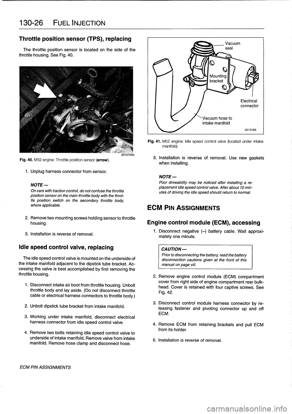
See
Fig
.
40
.
Fig
.
40
.
M52
engine
:
Throttle
position
sensor
(arrow)
.
1
.
Unplug
harness
connector
from
sensor
.
NOTE
-
On
cars
with
tractioncontrol,
do
not
confuse
the
throttieposition
sensor
on
the
main
throttie
body
wíth
the
throt-
tie
position
switch
on
the
secondary
throttie
body,
where
applicable
.
3
.
Installation
is
reverse
of
removal
.
¡die
speed
control
valve,
replacing
0012700b
The
¡die
speed
control
valve
is
mounted
on
the
underside
of
the
intake
manifoldadjacent
to
the
dipstick
tube
bracket
.
Ac-
cessing
the
valve
is
best
accomplished
by
first
removing
the
throttie
housing
.
1
.
Disconnect
intake
air
bootfrom
throttie
housing
.
Unbolt
throttie
body
and
¡ay
aside
.
(Do
not
disconnect
throttie
cable
or
electrical
harness
connectors
to
throttie
body
.)
2
.
Unbolt
dipstick
tube
bracket
from
intakemanifold
.
3
.
Workíng
under
intake
manifold,
disconnect
electrical
harness
connector
from
¡die
speed
control
valve
.
4
.
Remove
two
bolts
retaining
¡die
speed
control
valve
to
underside
of
intake
manifold
.
Remove
valve
from
intake
manifold
.
Remove
hose
clamp
and
disconnect
hose
.
ECM
PIN
ASSIGNMENTS
mately
one
minute
.
Vacuum
seal
Mounting
bracket
Electrical
connector
0013185
Fig
.
41
.
M52
engine
:
¡die
speed
control
valve
(located
under
intake
manifold)
.
5
.
Installation
ís
reverse
of
removal
.
Use
new
gaskets
when
installing
.
NOTE
-
Poor
driveabilíty
may
be
noticed
atter
installing
a
re-
placement
idle
speed
control
valve
.
After
about
10
min-utes
of
dríving
the
idle
speed
should
return
to
normal
.
ECM
PIN
ASSIGNMENTS
2
.
Remove
twomountingscrews
holding
sensor
to
throttie
housing
.
Engine
control
module
(ECM),
accessing
1
.
Disconnect
negative
(-)
battery
cable
.
Wait
approxi-
CAUTION-
Prior
to
disconnecting
the
battery,
read
the
battery
disconnection
cautions
given
at
the
front
of
this
manual
onpage
vüi
.
2
.
Remove
engine
control
module
(ECM)
compartment
cover
from
right
side
of
engine
compartment
rear
bulk-
head
.
Cover
is
retained
withfour
captíve
screws
.
See
Fig
.
42
.
3
.
Disconnect
control
module
harness
connector
by
re-
leasing
fastener
and
pivoting
connectorup
and
off
ECM
.
4
.
Remove
ECM
from
retaining
brackets
and
pull
ECM
from
its
holder
.
5
.
Installation
is
reverse
of
removal
.
Page 173 of 759
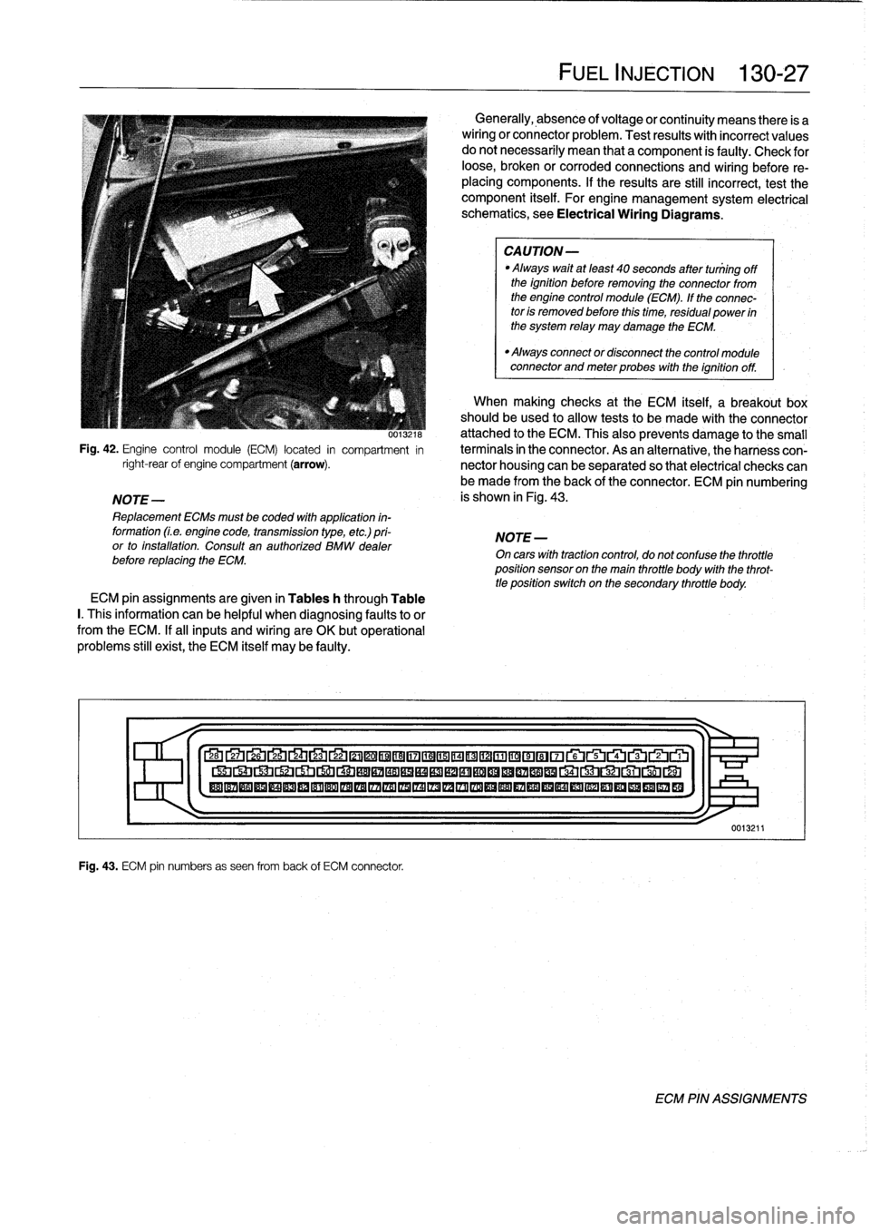
0013ZIM
Fig
.
42
.
Engine
control
module
(ECM)
located
in
compartment
in
right-rearof
engine
compartment
(arrow)
.
NOTE-
Replacement
ECMs
must
be
coded
with
application
in-
formation
(Le
.
engine
code,
transmission
type,
etc
.)
pri-
or
to
installation
.
Consult
an
authorized
BMW
dealer
before
replacing
the
ECM
.
ECM
pin
assignments
are
given
in
Tables
h
through
Table
I.
This
information
can
be
helpful
when
diagnosing
faultsto
or
from
the
ECM
.
If
al¡
inputs
and
wiring
are
OK
butoperational
problems
still
exist,
the
ECM
itself
may
be
faulty
.
Fig
.
43
.
ECM
pin
numbers
as
seen
from
back
of
ECM
connector
.
FUEL
INJECTION
130-
2
7
Generally,
absence
of
voltage
or
continuity
means
there
is
a
wiring
or
connector
problem
.
Test
results
with
incorrect
values
do
notnecessarily
mean
that
a
component
is
faulty
:
Check
for
loose,
broken
or
corroded
connections
and
wiring
before
re-
placing
components
.
If
the
results
are
still
incorrect,
test
the
component
itself
.
For
engine
management
system
electrical
schematics,
see
Electrical
Wiring
Diagrams
.
CAUTION-
Always
waitat
least
40
seconds
after
tuniing
off
the
ignition
before
removing
the
connector
from
the
engine
control
module
(ECM)
.
If
the
connec-
tor
is
removed
before
this
time,
residual
power
in
the
system
relay
may
damage
the
ECM
.
"
Always
connector
disconnect
the
control
module
connector
and
meter
probes
with
the
ignitionoff
.
When
making
checks
at
the
ECM
itself,
a
breakout
box
should
be
used
to
allow
tests
to
be
made
with
the
connector
attached
to
the
ECM
.
This
also
prevents
damage
tothe
small
termínals
in
the
connector
.
As
an
alternative,
theharness
con-
nector
housing
can
be
separated
so
that
electrical
checks
can
be
made
from
the
back
of
the
connector
.
ECM
pin
numbering
is
shown
in
Fig
.
43
.
NOTE
-
On
cars
with
tractioncontrol,
do
not
confuse
the
throttle
position
sensor
on
the
main
throttle
body
with
the
throt-
tle
position
switch
on
the
secondary
throttle
body
.
27
Lb
2L4
LJ
22
©©®®17
©©®©©~©©®©~~rui~~ru
®®®®®®®®®®®®®®®IZA®®®®®®®®®®®®®®®®®
1
>I-
0013211
ECM
PIN
ASSIGNMENTS
Page 187 of 759
2
.
Remove
fuel
tank
filler
cap
.
3
.
Remove
rearseat
cushion
and
pull
back
insulation
mats
to
expose
fuel
tank
access
covers
.
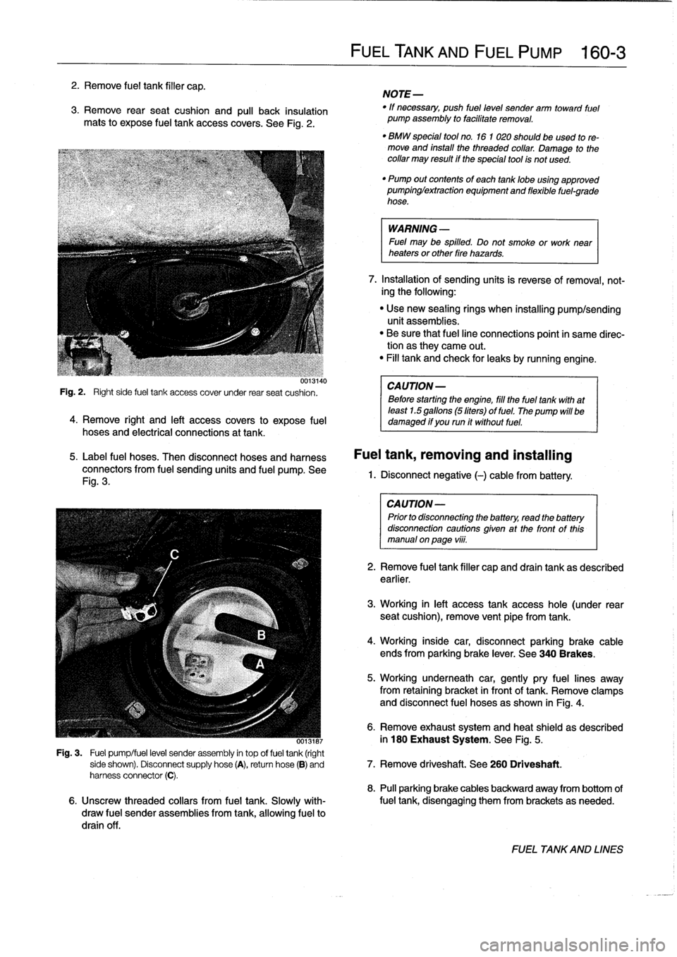
See
Fig
.
2
.
uui3140
Fig
.
2
.
Right
side
fuel
tank
access
cover
under
rear
seat
cushion
.
4
.
Remove
right
and
left
access
covers
to
expose
fuel
hoses
and
electrical
connections
at
tank
.
5
.
Label
fuel
hoses
.
Then
disconnect
hoses
and
harness
connectors
from
fuel
sending
units
and
fuel
pump
.
See
Fig
.
3
.
FUELTANK
AND
FUEL
PUMP
160-
3
NOTE-
"
If
necessary,
push
fuel
level
sender
arm
toward
fuel
pump
assembly
to
facilitate
removal
.
"
BMW
special
tool
no
.
16
1
020
should
beused
tore-
move
and
install
the
threaded
collar
.
Damage
to
thecollar
may
result
if
the
special
tool
is
not
used
.
"
Pump
out
contents
of
each
tanklobe
using
approved
pumpinglextraction
equipment
and
flexible
fuel-grade
hose
.
WARNING
-
Fuel
may
be
spilled
.
Do
not
smoke
or
work
near
heaters
or
other
fire
hazards
.
7
.
Installation
of
sending
units
is
reverse
of
removal,
not-
ing
the
following
:
"
Use
new
sealing
rings
when
installing
pump/sending
unit
assemblies
.
"
Be
sure
that
fuel
line
connections
point
in
same
direc-tion
as
they
carne
out
.
"
Fill
tank
and
check
for
leaks
by
running
engine
.
CA
UTION-
Before
starting
the
engine,
fill
the
fuel
tank
with
at
least
1.5
gallons
(5liters)
of
fuel
.
The
pump
will
be
damaged
if
you
run
it
without
fuel
.
Fuel
tank,
removing
and
installing
1.
Disconnect
negative
(-)cablefrom
battery
:
CAUTION-
Prior
to
disconnectiog
the
battery,
read
the
battery
disconnection
cautions
given
at
the
front
of
this
manual
onpage
viii
.
2
.
Remove
fuel
tank
filler
capand
drain
tank
as
described
earlier
.
3
.
Working
in
left
access
tank
access
hole
(under
rear
seat
cushion),
remove
vent
pipe
fromtank
.
4
.
Working
inside
car,
disconnectparking
brake
cable
ends
from
parking
brake
lever
.
See
340
Brakes
.
5
.
Working
underneath
car,
gently
pry
fuel
lines
away
from
retaining
bracket
in
front
of
tank
.
Remove
clamps
and
disconnect
fuel
hoses
as
shown
in
Fig
.
4
.
6
.
Remove
exhaust
system
and
heat
shield
as
described
ooisiai
in
180
Exhaust
System
.
See
Fig
.
5
.
Fig
.
3
.
Fuel
pump/fuel
level
sender
assembly
in
top
offuel
tank
(right
side
shown)
.
Disconnect
supply
hose
(A),
return
hose
(B)
and
7
.
Remove
driveshaft
.
See
260
Driveshaft
.
harness
connector
(C)
.
8
.
Pull
parking
brake
cables
backward
away
from
bottom
of
6
.
Unscrew
threaded
collars
from
fuel
tank
.
Slowly
with-
fuel
tank,
disengaging
them
from
brackets
as
needed
.
draw
fuel
sender
assemblies
from
tank,allowing
fuel
to
drain
off
.
FUEL
TANKAND
LINES
Page 189 of 759
Fuel
leve¡
senders,
testing
Fuel
leve¡
sender
(right
side)
The
left
and
right
fuelleve¡
sending
units
are
wired
in
series
.
and
fuel
pump,
removing
and
installing
The
fuel
gauge
receives
a
signal
that
is
the
average
of
the
two
1
.
Disconnect
negative
(-)
cable
from
battery
.
input
values
.
1
.
Remove
rear
seat
cushion,
lift
up
insulation
mats,
andremove
both
fuel
tank
access
covers
.
2
.
Disconnect
white
plug
on
each
sending
unit
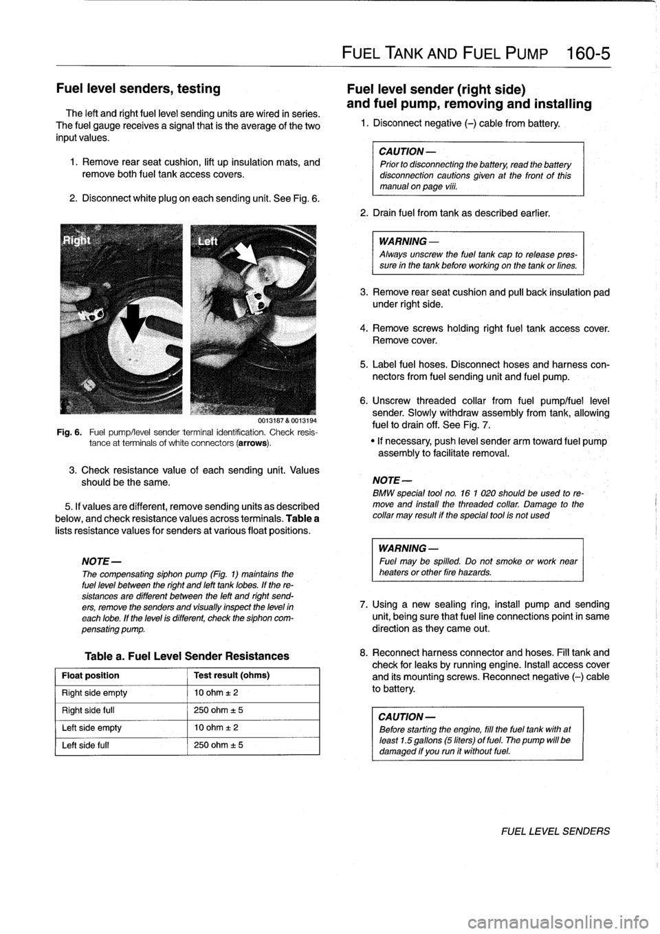
.
See
Fig
.
6
.
3
.
Check
resistance
value
of
eachsending
unit
.
Values
should
be
the
same
.
5
.
If
valuesare
different,
remove
sending
units
as
described
below,
and
check
resistance
valuésacross
terminals
.
Table
a
lists
resistance
values
for
senders
at
various
float
positions
.
Table
a
.
Fuel
Leve¡
Sender
Resistances
Float
position
Test
result
(ohms)
Right
side
empty
10
ohm
t2
Right
side
full
250
ohm
±
5
Left
side
empty
10
ohm
t
2
Left
side
fui¡
250
ohm
±
5
FUEL
TANK
AND
FUEL
PUMP
160-
5
CAUTION
-
Prior
to
disconnecting
the
battery,
read
the
battery
disconnection
cautionsglven
at
the
front
of
this
manual
onpage
viii
.
2
.
Drain
fuel
from
tank
as
described
earlier
.
WARNING
-
Always
unscrew
the
fuel
tank
cap
to
release
pres-
sure
in
the
tank
before
working
on
the
tank
or
fines
.
3
.
Remove
rear
seat
cushion
and
pull
back
insulation
pad
under
right
side
.
4
.
Remove
screws
holding
rightfuel
tank
accesscover
.
Remove
cover
.
5
.
Label
fuel
hoses
.
Disconnect
hoses
and
harness
con-
nectors
from
fuel
sending
unit
and
fuel
pump
.
6
.
Unscrew
threaded
collar
from
fuel
pumplfuel
leve¡
sender
.
Slowly
withdraw
assembly
from
tank,allowing
fuelto
drain
off
.
See
Fig
.
7
.
0013187
&
0013194
Fig
.
6
.
Fuel
pump/leve¡
sender
terminal
identification
.
Check
resis-
tance
at
terminals
of
white
connectors
(arrows)
.
"
If
necessary,
push
leve¡
sender
arm
toward
fuel
pump
assembly
to
facilitate
removal
.
NOTE
-
BMW
special
tool
no
.
16
1
020
should
beused
to
re-
move
and
install
the
threaded
collar
.
Damage
to
the
collar
may
result
if
the
special
tool
is
not
used
WARNING
-
NOTE-
Fuel
may
be
spilled
.
Do
not
smoke
or
work
near
The
compensating
siphon
pump
(Fig
.
1)
maintains
the
heaters
or
other
fire
hazards
.
fuel
leve¡
between
the
right
and
left
tank
lobes
.
If
the
re-
sistances
are
different
between
the
left
and
right
send-
ers,
remove
the
senders
and
visually
inspect
the
leve)
in
7
.
Using
a
new
sealing
ring,
install
pump
and
sending
each
lobe
.
If
the
leve¡
is
different,
check
the
siphon
com-
unit,
being
sure
that
fuel
line
connections
point
in
same
pensating
pump
.
direction
as
they
carne
out
.
8
.
Reconnect
harnessconnector
and
hoses
.
Fill
tank
and
check
for
leaks
by
running
engine
.
Insta¡¡
access
cover
and
its
mountingscrews
.
Reconnect
negative
(-)
cable
to
battery
.
CAUTION
-
Before
starting
the
engine,
fill
the
fuel
tank
with
at
least
1
.5
gallons
(5liters)
of
fuel
.
The
pump
will
be
damaged
if
you
run
it
without
fuel
.
FUEL
LEVEL
SENDERS
Page 191 of 759
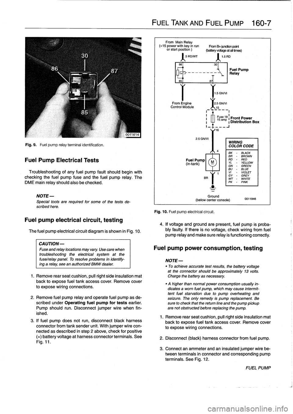
Fig
.
9
.
Fuel
pump
relay
terminal
identification
.
Fuel
Pump
Electrical
Tests
Troubleshooting
of
any
fuel
pump
fault
should
begin
with
checking
the
fuel
pump
fuse
and
the
fuel
pump
relay
.
The
DME
main
relay
should
also
be
checked
.
NOTE-
Special
tools
are
requíred
for
some
of
the
tests
de-
scribed
here
.
Fuel
pump
electrical
circuit,
testing
The
fuel
pump
electrical
circuit
diagram
is
shown
in
Fig
.
10
.
3
.
If
fuel
pump
does
not
run,
disconnect
black
harness
connector
from
tank
sender
unit
.
With
jumper
wire
con-
nectedas
described
in
step
2
above,
check
for
positive
(+)
batteryvoltage
at
harness
connector
terminals
.
See
Fig
.
11
.
FUEL
TANK
AND
FUEL
PUMP
160-
7
From
Main
Relay
(+15
power
with
key
in
run
From
B+juretion
point
orstartposition)
(batteryvoRageatalltirnes)
'
.5
RD/Nrr
1
.5
RD
1
.5
GNNI
From
Engine
2
.5
GNNI
Control
Module
15
2
.5
GNNI
Ground
(below
center
console)
Fig
.
10
.
Fuel
pump
electrical
circuit
.
30
-~
Relay
Fuel
Pump
8~T
I
1
s
ám
61
Front
Power
I
a
1
Distribution
Box
I_
16
WIRING
COLOR
CODE
BK
-
BLACK
BR
-
BROWN
Fuel
Pump
RD
-
RED
(in-tank)
M
YL
YELLOWGN
-
GREENBU
-
BLUE
1
VI
-
VIOLET
GY
-
GREY
WT
-
WHITE
PK
-
PINK
0011946
4
.
If
voltage
and
groundare
present,
fuel
pump
is
proba-
bly
faulty
.
If
there
is
no
voltage,
check
wiring
From
fuel
pump
Reay
and
make
sure
Reay
is
functioning
correctly
.
CAUTION-
Fuseandrelaylocationsmayvary
.
Usecara
when
Fuel
pump
power
consumption,
testing
troubleshooting
the
electrical
system
at
the
fuselrelay
panel
.
To
resolve
problems
in
identify-
NOTE-
ing
a
relay,
see
en
authorízed
BMW
dealer
.
"
To
achieveaccurate
testresults,
fhe
battery
voltage
at
the
connector
should
be
approximately
13
volts
.
1.
Remove
rearseat
cushion,
pull
right
side
insulation
mat
Charge
the
battery
asnecessary
.
back
to
expose
fuel
tank
accesscover
.
Remove
cover
.
q
higher
than
normal
power
consumption
usually
fin-
to
expose
wiring
connections
.
dicates
a
worn
fuel
pump,
which
may
cause
intermit-
tentfuel
starvation
due
lo
pump
overheating
and
2
.
Remove
fuel
pump
relay
and
opérate
fuel
pump
as
de-
seizure
.
The
only
remedy
is
pump
replacement
.
Be
scribed
under
Operating
fuel
pump
for
tests
earlier
.
sure
to
check
that
thereturn
fine
and
the
pump
pickup
Pump
should
run
.
Disconnect
jumper
wire
when
fin-
are
not
obstructed
before
replacing
the
pump
.
ished
.
1
.
Remove
rear
seat
cushion,
pull
right
side
insulation
mal
back
to
expose
fuel
tank
accesscover
.
Remove
cover
to
expose
wiring
connections
.
2
.
Disconnect
(black)
harness
connector
from
fuel
pump
.
3
.
Connect
an
ammeter
and
an
insulated
jumper
wire
be-
tween
terminals
in
connector
and
corresponding
pump
terminals
.
See
Fig
.
12
.
FUEL
PUMP