sensor BMW M3 1998 E36 Owner's Manual
[x] Cancel search | Manufacturer: BMW, Model Year: 1998, Model line: M3, Model: BMW M3 1998 E36Pages: 759
Page 74 of 759
113-8
CYLINDER
HEAD
REMOVAL
AND
INSTALLATION
IW?
-
L
'/~f
W
~
4r
"
-
"
;,s
1
12
.
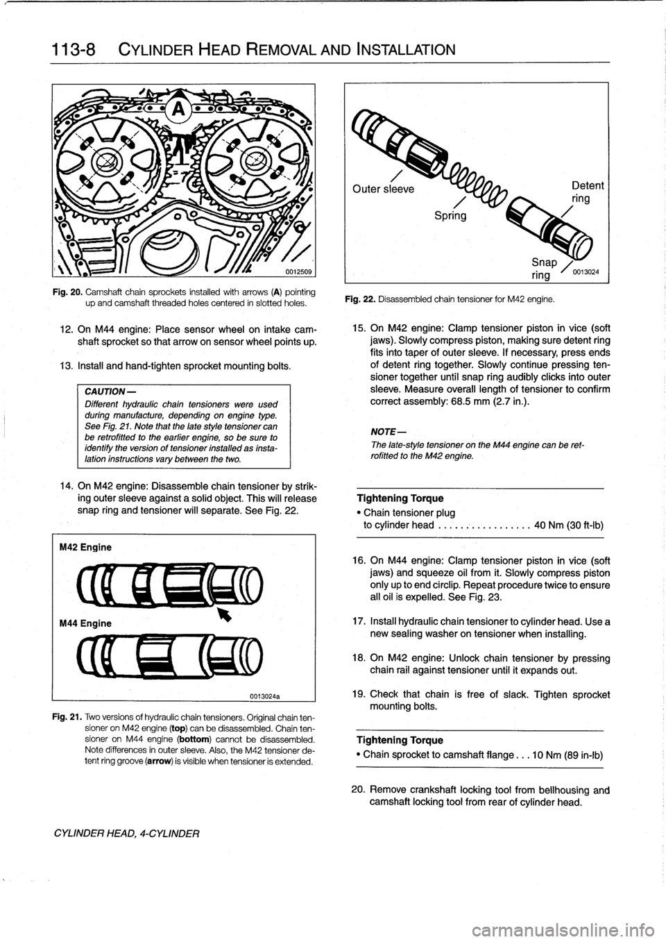
On
M44
engine
:
Place
sensor
wheel
on
intake
cam-
shaft
sprocket
so
that
arrowon
sensor
wheel
points
up
.
13
.
Instan
and
hand-tighten
sprocket
mounting
bolts
.
CAUTION-
Different
hydraulic
chaintensioners
were
used
during
manufacture,
depending
onengine
type
.
See
Fig
.
21
.
Note
that
the
late
style
tensioner
can
be
retrofitted
to
the
earlier
engine,
so
be
sure
to
identify
the
version
of
tensioner
installed
as
insta-lation
instructions
vary
between
the
two
.
14
.
On
M42
engine
:
Disassemble
chain
tensioner
by
strik-
ing
outer
sleeve
against
a
solid
object
.
This
will
release
snap
ring
and
tensioner
will
separate
.
See
Fig
.
22
.
M42
Engine
up
and
camshaft
threaded
holes
centered
in
siotted
holes
.
CYLINDER
HEAD,
4-CYLINDER
0013024a
Outer
sl
eve
Detent
ring
Spri
g
Fig
.
22
.
Disassembled
chain
tensioner
for
M42
engine
.
15
.
On
M42
engine
:
Clamp
tensioner
piston
in
vice
(soft
jaws)
.
Slowly
compress
piston,
making
sure
detent
ring
fits
into
taper
of
outer
sleeve
.
If
necessary,
press
ends
of
detent
ring
together
.
Slowly
continuepressing
ten-
sioner
together
until
snap
ring
audibly
clicksinto
outer
sleeve
.
Measure
overall
lengthof
tensioner
to
confirm
correct
assembly
:
68
.5
mm
(2.7
in
.)
.
NOTE-
i
Snap
ring
/0
.13024
The
late-style
tensioner
on
the
M44
engíne
canbe
ret-
rofitted
to
the
M42
engine
.
Tightening
Torque
"Chain
tensioner
plug
to
cylinder
head
.....
.-~
..........
40
Nm
(30
ft-Ib)
16
.
On
M44
engíne
:
Clamp
tensioner
píston
in
vice
(soft
jaws)
and
squeeze
oil
from
it
.
Slowly
compress
piston
only
up
to
end
circlip
.
Repeat
procedure
twice
to
ensure
all
oil
is
expelled
.
See
Fig
.
23
.
17
.
Instan
hydraulic
chain
tensioner
to
cylinder
head
.
Use
a
new
sealing
washer
on
tensioner
when
installing
.
18
.
On
M42
engine
:
Unlock
chain
tensioner
by
pressing
chain
rail
against
tensioner
until
it
expands
out
.
19
.
Check
that
chain
is
free
of
slack
.
Tighten
sprocket
mounting
bolts
.
Fig
.
21
.
Two
versions
of
hydraulic
chain
tensioners
.
Original
chainten-
sioner
on
M42
engine
(top)
can
be
disassembled
.
Chain
ten
sioner
on
M44
engine
(bottom)
cannotbe
disassembled
.
Tightening
Torque
Note
differences
in
outer
sleeve
.
Also,
the
M42
tensioner
de-
"
Chain
sprocket
to
camshaft
flange
.
..
10
Nm
(89
in-lb)
tent
ring
groove
(arrow)
is
visible
when
tensioner
is
extended
.
20
.
Remove
crankshaft
locking
tool
from
bellhousing
and
camshaft
locking
tool
from
rear
of
cylinder
head
.
Page 75 of 759
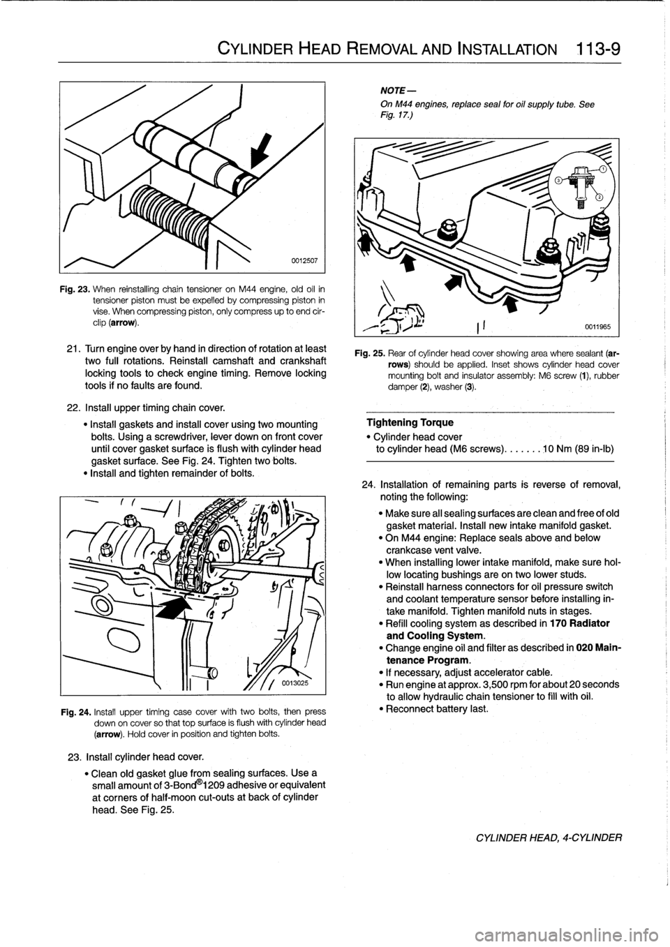
Fig
.
23
.
When
reinstalling
chain
tensioner
on
M44
engine,
old
oil
in
tensioner
piston
mustbe
expelled
bycompressing
piston
in
vise
.
When
compressing
piston,
only
compress
up
to
end
cir-
clip
(arrow)
.
21
.
Turn
engine
overby
hand
in
direction
of
rotation
at
least
two
fui¡
rotations
.
Reinstall
camshaft
and
crankshaft
locking
tools
to
check
engíne
timing
.
Remove
locking
tools
if
no
faults
are
found
.
22
.
Insta¡¡
upper
timingchain
cover
.
"
Install
gaskets
and
instan
cover
using
two
mounting
Tightening
Torque
bolts
.
Using
a
screwdriver,
lever
down
on
front
cover
"
Cylinder
head
cover
until
cover
gasket
surface
is
flush
with
cylinder
head
to
cylinder
head
(M6
screws)
.......
10
Nm
(89
in-lb)
gasket
surface
.
See
Fig
.
24
.
Tighten
two
bolis
.
"
Insta¡¡
and
tighten
remainder
of
bolis
.
23
.
Install
cylinder
head
cover
.
CYLINDER
HEAD
REMOVAL
AND
INSTALLATION
113-
9
0012507
Fig
.
24
.
Install
upper
timing
case
cover
with
two
bolis,
then
press
down
on
cover
so
that
top
surface
is
flush
withcylinder
head
(arrow)
.
Hold
cover
in
position
and
tighten
bolis
.
"
Clean
old
gasket
glue
from
sealing
surfaces
.
Usea
small
amount
of
3-Bond
®
1209
adhesive
or
equivalent
at
corners
of
half-moon
cut-outs
at
back
of
cylinder
head
.
See
Fig
.
25
.
NOTE-
OnM44
engines,
reptace
sea¡
for
oil
supply
tube
.
See
Fig
.
17
.)
Fig
.
25
.
Rear
of
cylinder
head
cover
showing
area
where
sealant
(ar-
rows)
should
be
applied
.
Inset
shows
cylinder
head
cover
mounting
bolt
and
insulator
assembly
:
M6
screw
(1),
rubber
damper
(2),
washer
(3)
.
24
.
Installation
of
remaining
parts
is
reverseofremoval,
noting
the
following
:
"
Make
sure
al¡
sealing
surfaces
are
clean
and
free
of
old
gasket
material
.
Install
new
intake
manifold
gasket
.
"
On
M44
engine
:
Replace
seals
above
and
below
crankcase
ventvalve
.
"
When
installing
lower
intake
manifold,
make
sure
hol-
low
locating
bushings
are
on
two
lower
studs
.
"
Reinstall
harness
connectors
for
oil
pressure
switch
and
coolant
temperature
sensor
before
installing
in-
take
manifold
.
Tighten
manifold
nuts
in
stages
.
"
Refill
cooling
system
as
described
in
170
Radiator
and
Cooling
System
.
"
Change
engine
oil
and
filter
as
described
in
020
Main-
tenance
Program
.
"
If
necessary,
adjust
accelerator
cable
.
"
Run
engine
at
approx
.
3,500
rpm
for
about
20
seconds
to
allow
hydraulic
chain
tensioner
to
fill
with
oil
.
"
Reconnect
battery
last
.
CYLINDER
HEAD,-CYLINDER
Page 76 of 759
113-10
CYLINDER
HEAD
REMOVAL
AND
INSTALLATION
Tightening
Torques
"
Coolant
drain
plug
to
cylinder
block
.
.
25
Nm
(18
ft-1b)
"
Intake
manifold
support
to
manifold
.
.
15
Nm
(11
ft-Ib)
"
Lower
intake
manifold
to
cylinder
head
.
..........
.
..
...
15
Nm
(11
ft-Ib)
"
Lower
intake
manifold
to
upper
manifold
..........
.
..
...
15
Nm
(11
ft-Ib)
"
Radiator
cooling
fan
to
coolant
pump
.
40
Nm
(30
ft-Ib)
"
Radiator
drain
screw
to
radiator
...
.
2
.5
Nm
(22
in-lb)
CYLINDER
HEAD,
6-CYLINDER
For
ease
of
use
this
procedure
is
broken
into
subsections,
as
follows
:
General
Coolingsystem,
draining
Cyiinder
head
cover,
removing
Intake
manifold,
removing
Timing
chains,
uncoupling
Cylinder
head
assembly,
removing
WARNING
-
Allow
the
engine
to
cool
before
beginning
this
pro-
cedure
.
General
1
.
Working
inside
luggage
compartment,
disconnect
neg-
ative
(-)
battery
cable
.
CAUTION-
"
Prior
to
disconnectiog
the
battery,
read
the
bat-
tery
disconnection
cautions
given
at
the
front
of
this
manual
on
page
vi¡¡
.
"
Disconnecting
the
battery
may
erase
fault
code(s)
stored
in
control
module
memory
.
Check
for
fault
codes
using
special
BMW
diagnostic
equipment
2
.
Remove
front
exhaust
pipes
from
manifolds
.
Discard
nuts
.
3
.
Remove
air
filter
housing
complete
with
mass
air
flow
sensor
and
intake
air
ducting
.
Disconnect
vacuum
hos-
es
from
throttle
housing
.
4
.
On
M52
and
S52US
engines
:
Remove
secondary
air
injection
check-valve
from
front
of
engine
and
set
aside
.
CYLINDER
HEAD,
6-CYLINDER
Coolingsystem,
draining
5
.
Drain
engine
coolant
and
Rmove
coolant
hoses
from
thermostat
housing
.
Drain
engine
block
by
removing
block
drain
.
See
170
Radiator
and
Cooling
System
.
NOTE-
The
block
drain
is
on
the
exhaust
side
of
the
engine,
near
cylinder
no
.
5
.
6
.
Remove
radiator
cooling
fan
and
fan
shroud
.
See
170
Radiator
and
Cooling
System
.
NOTE-
The
radiator
cooling
fannut(32
mm
wrench)
has
left-
hand
threads
.
Cylinder
head,
removing
(6-cylinder
engine)
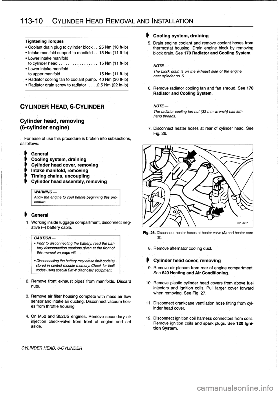
7
.
Disconnect
heater
hoses
at
rear
of
cylinder
head
.
See
Fig
.
26
.
'i
8
.
Remove
alternator
cooling
duct
.
Cylinder
head
cover,
removing
0012687
Fig
.
26
.
Disconnect
heater
hoses
at
heater
valve
(A)
and
heater
core
(B)
.
9
.
Remove
air
plenum
from
rear
of
engine
compartment
.
See640
Heating
and
Air
Conditioning
.
10
.
Remove
plastic
cylinder
head
covers
from
above
fuel
injectors
and
ignition
coils
.
Pull
larger
cover
forward
when
removing
.
See
Fig
.
27
.
11
.
Disconnect
crankcase
ventílation
hose
fitting
from
cyl-
inder
head
cover
.
12
.
Disconnect
ignition
coil
harness
connectors
from
coiis
.
Remove
ignition
coiis
and
spark
plugs
.
See
120
Igni-
tion
System
.
Page 84 of 759
113-
1
8
CYLINDER
HEAD
REMOVAL
AND
INSTALLATION
CYLINDER
HEAD,
6-CYLINDER
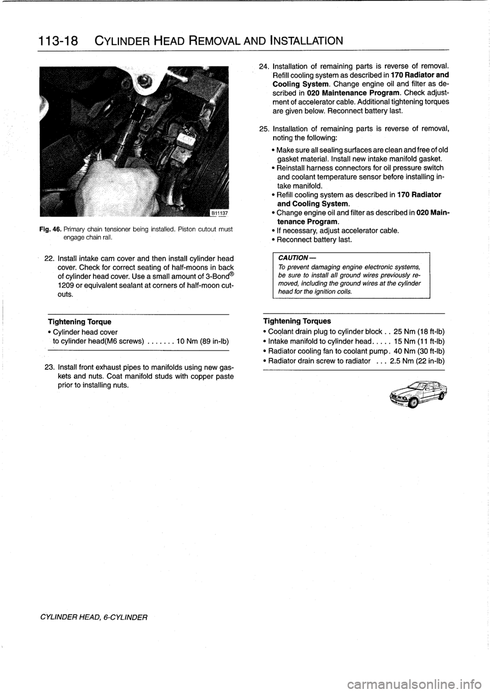
Fig
.
46
.
Primary
chaintensioner
being
installed
.
Piston
cutout
must
engage
chain
rail
.
22
.
Install
intake
cam
cover
and
then
install
cylinder
head
cover
.
Check
for
correct
seating
of
half-moons
in
back
of
cylinder
head
cover
.
Use
a
small
amount
of
3-Bond
O
1209
orequivalent
seaiant
at
corners
of
half-moon
cut-
outs
.
23
.
Install
front
exhaust
pipes
to
manifolds
using
new
gas-
kets
and
nuts
.
Coat
manifold
studs
with
copper
paste
prior
to
installing
nuts
.
24
.
Installationof
remaining
parts
is
reverse
of
removal
.
Refill
cooling
system
as
described
in
170
Radiator
and
Cooling
System
.
Change
engine
oil
and
filter
as
de
scribed
in
020
Maintenance
Program
.
Check
adjust-
ment
of
accelerator
cable
.
Additional
tightening
torques
are
given
below
.
Reconnect
battery
last
.
25
.
Installationof
remaining
parts
is
reverse
of
removal,
noting
the
following
:
"
Make
sure
all
sealing
surfaces
are
clean
and
free
of
old
gasket
material
.
Insta¡¡
new
intake
manifold
gasket
.
"
Reinstall
harness
connectors
for
oil
pressure
switch
and
coolant
temperature
sensor
before
installing
in-
take
manifold
.
"
Refill
cooling
systemas
described
in
170
Radiator
and
Cooling
System
.
"
Change
engine
oil
and
filter
as
described
in
020
Main-
tenance
Program
.
"
If
necessary,
adjust
accelerator
cable
.
"
Reconnect
battery
last
.
CAUTION-
To
prevent
damaging
engine
electronic
systems,
be
sure
to
install
all
ground
wirespreviously
re-
moved,
including
the
ground
wires
at
the
cylinder
head
for
the
ignition
coils
.
Tightening
Torque
Tightening
Torques
"
Cylinder
head
cover
"
Coglant
drain
plug
to
cylinder
block
.
.
25
Nm
(18
ft-Ib)
to
cylinder
head(M6
screws)
.
.
.....
10
Nm
(89
in-lb)
"
Intake
manifold
to
cylinder
head
.
...
.
15
Nm
(11
ft-Ib)
"
Radiator
cooling
fan
to
coolant
pump
.
40
Nm
(30
ft-Ib)
"
Radiator
drain
screw
to
radiator
.
..
2
.5
Nm
(22
in-lb)
Page 98 of 759
117-2
CAMSHAFT
TIMING
CHAIN
CAMSHAFT
TIMING
CHAIN,
4-CYLINDER
Special
BMW
service
tools
are
needed
for
timing
chain
re-
moval
and
installation
procedures
.
The
special
tools
assure
proper
timing
of
the
valvetrain
.
Precíse
marks
to
setthe
timing
on
the
camshafts
are
not
provided
for
reassembly
.
Read
the
procedures
through
before
beginning
the
job
.
CAUTION-
lf
the
camshaftsare
not
properly
timed,
the
pis-
tons
can
contact
thevalves
.
Camshaft
timing
chain,
removing
(4-cylinder
engines)
U0119-
Fig
.
3
.
Upper
timing
chain
covermounting
bolts(arrows)
.
Thermo-
1
.
Disconnect
negative
(-)cablefrom
battery
.
stat
housing
shown
removed
.
Cylinder
ídentification
sensor
(A)
also
shown
.
CAUTION-
Prior
to
disconnecting
the
battery,
read
the
battery
disconnection
cautions
given
at
the
front
of
this
manual
on
page
viii
.
2
.
Drain
engine
coolant
.
Drain
engine
block
byremoving
block
drain
.
Remove
radiator
cooling
fan
shroud
and
cooling
fan
.
See
170
Radiator
and
Cooling
System
..
WARNING
-
Allow
the
engine
to
cool
before
openingor
draining
the
cooling
system
.
CA
UTION-
On
cars
with
viscous-type
fan
clutch,
fan
has
left
hand
threads
.
NOTE-
The
block
drain
plug
is
located
on
the
exhaust
sideof
the
engine,
below
cylinder
no
.
4
.
3
.
Remove
cylinder
head
cover
.
See
113
Cylinder
HeadRemoval
and
Installation
.
NOTE-
Make
note
of
the
arrangement
of
the
rubber
insulators
when
removing
the
cylinder
head
cover
mounting
belts
.
4
.
Loosen
sparkplugs
.
See
120
Ignition
System
.
5
.
Disconnect
coolant
hoses
from
thermostat
housingon
front
of
cylinder
head
.
Unbolt
thermostat
housing
from
cylinder
head
.
6
.
Remove
cylinder
identification
sensor
from
upper
tim-
ing
chain
cover
.
Remove
upper
timing
chain
cover
.
See
Fig
.
3
.
CAMSHAFT
TIMING
CHAIN,
4-CYLINDER
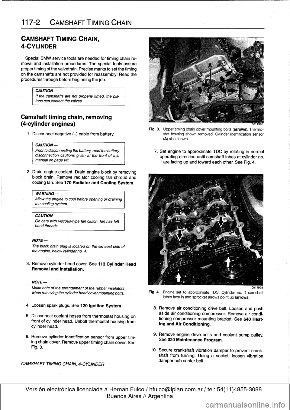
7
.
Set
engine
to
approximate
TDC
by
rotating
in
normal
operating
direction
until
camshaft
lobes
at
cylinder
no
.
1
are
facing
up
and
toward
each
other
.
See
Fig
.
4
.
0011998
Fig
.
4
.
Engine
set
to
approximate
TDC
.
Cylinder
no
.
1
camshaft
lobes
face
in
and
sprocket
arrows
point
up
(arrows)
.
8
.
Remove
air
conditioning
drive
belt
.
Loosenand
push
aside
air
conditioning
compressor
.
Remove
air
condi-
tioning
compressor
mounting
bracket
.
See
640
Heat-
ing
and
Air
Conditioning
.
9
.
Remove
engine
drive
belts
and
coolant
pump
pulley
.
See
020
Maintenance
Program
.
10
.
Secure
crankshaft
vibration
damper
to
prevent
crank-
shaft
from
turning
.
Using
a
socket,
loosen
vibration
damper
hub
center
bolt
.
Page 100 of 759
117-
4
CAMSHAFT
TIMING
CHAIN
15
.
Remove
mounting
bolts
from
left
and
right
camshaft
4
.
Insta¡¡
and
hand-tighten
sprocket
mounting
bolts
.
sprockets
.
16
.
On
M42
engines,
remove
upper
bolt
on
right
side
chainguide
and
unbolt
lower
timing
chainguide
below
crank-
shaft
.
17
.
Remove
camshaft
sprockets
from
camshafts
together
with
chain
and
crankshaft
sprocket
.
NoteWoodruffkey
when
removing
crankshaftsprocket
.
CA
UTION-
The
crankshaft
must
not
be
allowed
to
rotate
when
the
timing
chaín
is
removed
.
The
pistons
can
contact
the
valves
.
Camshaft
timing
chain,
installing
(4-cylinder
engines)
Inspectal¡
sprockets
for
wear
or
damage
.
Inspect
the
chain
guide
and
tensioner
rails
for
grooves
caused
by
chain
contact
.
Replace
any
partthat
is
worn
.
If
any
of
the
sprockets
are
worn,
the
chain
and
sprocketsare
replaced
asan
assembly
.
The
procedure
outlined
below
assumes
that
the
camshafts
and
the
crankshaft
arelocked
in
the
TDC
installation
positionwithspecial
tools
(shown
earlier
in
Fig
.
5
and
Fig
.
6)
.
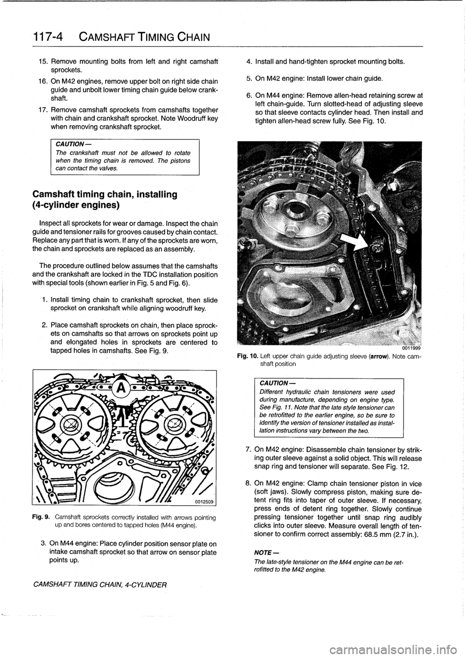
1
.
Install
timing
chain
to
crankshaft
sprocket,
then
slide
sprocket
on
crankshaft
whílealigníng
woodruff
key
.
2
.
Place
camshaft
sprockets
on
chain,
then
place
sprock-
ets
oncamshafts
so
that
arrows
on
sprockets
point
up
and
elongatedholes
in
sprockets
are
centered
lo
tapped
holes
in
camshafts
.
See
Fig
.
9
.
.
I
Pa
-
s
~_
a
Ge
..
.
0012509
5
.
On
M42
engine
:
Install
lowerchainguide
.
6
.
On
M44
engine
:
Remove
allen-head
retaining
screw
at
left
chain-guide
.
Turn
slotted-head
of
adjusting
sleeve
so
that
sleeve
contacts
cylinder
head
.
Then
install
and
tighten'allen-head
screw
fully
.
See
Fig
.
10
.
Fig
.
10
.
Left
upper
chain
guide
adjusting
sleeve
(arrow)
.
Note
cam-
shaft
position
CAUTION-
Different
hydraulic
chaintensioners
were
used
duringmanufacture,
depending
onengíne
type
.
See
Fig
.
11
.
Note
that
the
late
style
tensioner
canbe
retrofitted
to
the
earlier
engíne,
so
be
sure
to
identify
the
versíon
of
tensioner
ínstalled
as
ínstal-
lation
instructions
vary
between
the
two
.
7
.
On
M42
engine
:
Disassemble
chain
tensioner
by
strik-
ing
outer
sleeve
against
a
solid
object
.
This
will
release
snap
ring
and
tensioner
will
separate
.
See
Fig
.
12
.
8
.
On
M42
engine
:
Clamp
chain
tensioner
piston
in
vice
(soft
jaws)
.
Slowly
compress
piston,
making
sure
de-
tent
ring
fits
into
taper
of
outer
sleeve
.
If
necessary,
press
ends
of
detent
ring
together
.
Slowly
continueFig
.
9
.
Camshaft
sprockets
correctly
installed
with
arrows
pointing
pressing
tensioner
together
until
snap
ring
audibly
upand
bores
centered
to
tapped
holes
(M44
engine)
.
clicks
into
outer
sleeve
.
Measure
overall
length
of
ten-
sionerto
confirm
correct
assembly
:
68
.5
mm
(2
.7
in
.)
.
3
.
On
M44
engine
:
Place
cylinder
position
sensor
plate
on
intake
camshaft
sprocket
so
that
arrowonsensor
plate
NOTE-
points
up
.
The
¡ate-style
tensioner
on
the
M44
engine
can
be
ret-rofittedto
the
M42
engíne
.
CAMSHAFT
TIMING
CHAIN,
4-CYLINDER
Page 103 of 759
Camshaft
timing
chains,
removing
(6-cylinder
engines)
1
.
Disconnect
negative
(-)
cable
from
battery
.
CA
UTION-
Disconnecting
the
battery
may
erase
fault
codes)
stored
in
control
module
memory
.
Check
for
fault
codes
using
special
BMW
diagnostic
equipment
.
2
.
Drain
engine
coolant
.
Drain
engine
block
by
removing
block
drain
.
Remove
radiator
cooling
fan
shroud
and
cooling
fan
.
See170
Radiator
and
Cooling
System
.
.
WARNING
-
Allow
the
engine
to
cool
before
openingor
draining
the
system
.
CAUTION-
Radiator
fan
has
left
hand
threads
.
NOTE-
The
block
drain
plug
is
located
on
the
exhaust
side
of
the
engine,
below
cylinder
no
.
4
.
3
.
Drain
engine
oíl
andremove
oil
pan
.
See
119
Lubrica-
tion
System
.
4
.
Remove
alternator
cooling
duct
.
5
.
Remove
two
large
coolant
hoses
from
thermostat
housing
.
Remove
engine
lifting
bracket
and
thermostat
housing
from
front
of
cylinder
head
.
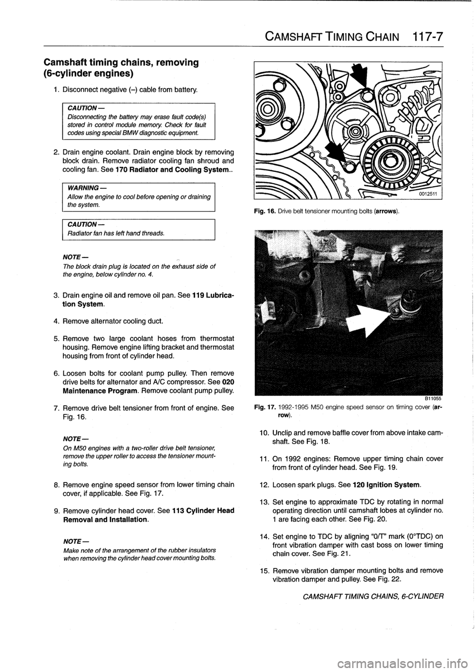
6
.
Loosen
bolts
for
coolant
pump
pulley
.
Then
remove
drive
belts
for
alternator
andA/C
compressor
.
See
020
Maintenance
Program
.
Remove
coolant
pump
pulley
.
Fig
.
16
.
NOTE-
OnM50
engines
with
a
two-roller
drive
belt
tensioner,
remove
the
upper
rollerto
access
thetensioner
mount-
ing
bolts
.
NOTE-
Make
note
of
the
arrangement
of
the
rubber
insulators
when
removing
the
cylinder
head
cover
mounting
bolts
.
CAMSHAFT
TIMING
CHAIN
117-
7
Fig
.
16
.
Drive
belt
tensioner
mounting
bolts
(arrows)
.
B11055
7
.
Remove
drive
belt
tensioner
from
front
of
engine
.
See
Fig
.
17
.
1992-1995
M50
engine
speed
sensor
on
timing
cover
(ar-
row)
.
10
.
Unclip
andremove
baffle
cover
from
above
intake
cam-
shaft
.
See
Fig
.
18
.
11
.
On
1992
engines
:
Remove
upper
timing
chain
cover
from
front
of
cylinder
head
.
See
Fig
.
19
.
8
.
Remove
engine
speed
sensor
from
lower
timing
chain
12
.
Loosen
spark
plugs
.
See
120
Ignition
System
.
cover,
if
applicable
.
See
Fig
.
17
.
13
.
Set
engine
to
approximate
TDC
by
rotating
in
normal
9
.
Remove
cylinder
head
cover
.
See
113
Cylinder
Head
operating
direction
until
camshaft
lobes
at
cylinder
no
.
Removal
and
Installatíon
.
1
are
facing
each
other
.
See
Fig
.
20
.
14
.
Set
engine
to
TDC
by
aligning
"0/T'
mark
(0°TDC)on
front
vibration
damper
with
cast
bosson
lower
timing
chain
cover
.
See
Fig
.
21
.
15
.
Remove
vibration
damper
mounting
bolts
and
remove
vibration
damper
and
pulley
.
See
Fig
.
22
.
CAMSHAFT
TIMING
CHAINS,
6-CYLINDER
Page 118 of 759
119-
4
LUBRICATION
SYSTEM
15
.
Remove
oil
pan
screws
.
Lower
andremove
oil
pan
to-
ward
rear
.
Tightening
Torques
"
Control
arm
bushing
carrier
CAUTION-
to
body(M10
bolt)
...............
42
Nm
(31
ft-Ib)
'
lf
the
oil
pan
does
not
separate
easily
from
the
en-
"
Engine
mount
to
gine
cylinder
block,
make
sure
all
mounting
bolis
suspension
crossmember
(M10
nut)
.
42
Nm
(31
ft-Ib)
have
been
removed
.
If
necessary,
a
few
tapswith
"
Front
suspension
crossmember
a
rubber
mallet
shouldbreak
it
free
.
Never
pry
the
to
body
.
.
..
...
..
.
....
See
310
Front
SusPension
oil
pan
loose
.
"
Oil
pan
to
engine
block
(M6
bolt)
8
.8
grade
..
....
.
...
...
.
........
10
Nm
(89
in-lb)
16
.
Installation
is
reverse
of
removal
.
10
.9
grade
...
..
.
....
..
.
.
.
.......
12
Nm
(9
ft-Ib)
"
Thoroughly
clean
all
old
gasket
material
from
mating
"
Power
steering
pump
to
bracket
surfaces
anduse
a
new
gasket
.
(self-locking
nuts)
....
..
.
....
..
.
..
22
Nm
(16
ft-Ib)
"
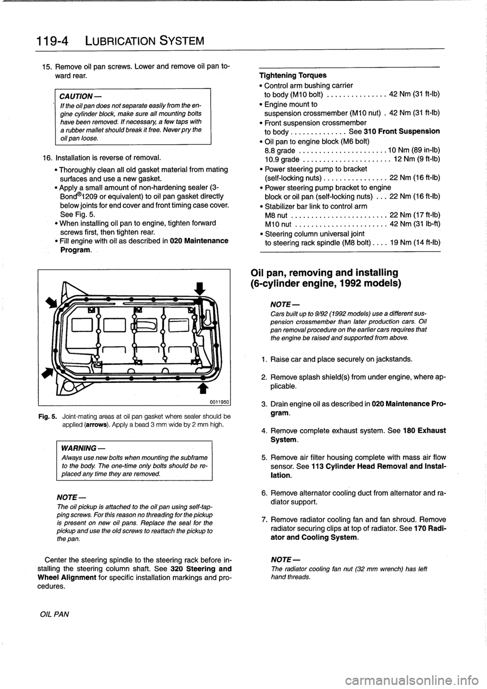
Applya
small
amount
of
non-hardening
sealer
(3-
"
Power
steering
pump
bracket
to
engine
Bond
O
l209
or
equivalent)
to
oil
pan
gasket
directly
block
or
oil
pan
(self-locking
nuts)
..
.
22
Nm
(16
ft-Ib)
below
joints
for
end
cover
and
front
timing
case
cover
.
"
Stabilizer
bar
link
to
control
arm
See
Fig
.
5
.
M8
nut
.................
...
.
...
22
Nm
(17
ft-Ib)
"
When
installing
oil
pan
to
engine,
tighten
forward
M10
nut
.....................
..
42
Nm
(31
Ib-ft)
screws
first,
then
tightenrear
.
"
Steering
column
universal
joint
"
Fill
engine
with
oil
as
described
in
020
Maintenance
to
steering
rack
spindle
(M8
bolt)
....
19
Nm
(14
ft-ib)
Program
.
0011950
Fig
.
5
.
Joint-mating
areas
at
oil
pan
gasket
where
sealer
should
be
applied
(arrows)
.
Apply
a
bead
3
mm
wideby
2
mm
high
.
OIL
PAN
WARNING
-
Always
use
new
bolis
when
mounting
the
subframe
to
the
body
.
The
one-timeonly
bolis
shouldbe
re-
placed
any
timethey
are
removed
.
NOTE-
The
oil
pickup
is
attached
to
the
oil
pan
using
self-tap-
ping
screws
.
For
this
reasonno
threading
for
the
pickup
is
present
on
new
oil
pans
.
Replace
the
seal
for
the
pickup
and
use
the
oíd
screws
to
rea
ttach
the
pickup
to
the
pan
.
Oil
pan,
removing
and
installing
(6-cylinder
engine,
1992models)
NOTE-
Cars
built
up
to
9/92
(1992models)usea
different
sus-
pension
crossmember
than
later
production
cars
.
Oil
pan
removalprocedureon
the
earlier
cars
requires
that
the
engine
be
raised
and
supportedfrom
above
.
1
.
Raise
car
and
place
securely
on
jackstands
.
2
.
Remove
splash
shield(s)
from
under
engine,
where
ap-
plicable
.
3
.
Drain
engine
oil
as
described
in
020
Maintenance
Pro-
gram
.
4
.
Remove
complete
exhaust
system
.
See180
Exhaust
System
.
5
.
Remove
air
filter
housing
complete
with
mass
air
flow
sensor
.
See
113
Cylinder
Head
Removal
and
Instal-
lation
.
6
.
Remove
alternator
cooling
duct
from
alternator
and
ra-
diator
support
.
7
.
Remove
radiator
cooling
fan
and
fan
shroud
.
Remove
radiator
securing
clips
at
top
of
radiator
.
See
170
Radi-
ator
and
Cooling
System
.
Center
the
steering
spindle
to
the
steering
rack
before
in-
NOTE-
stalling
the
steering
column
shaft
.
See
320
Steering
and
The
radiator
cooling
fan
nut(32
mm
wrench)
has
left
Wheel
Alignment
for
specific
installation
markings
and
pro-
hand
threads
.
cedures
.
Page 121 of 759
5
.
Remove
air
filter
housingcomplete
with
mass
air
flow
sensor
.
See113
Cylinder
HeadRemoval
and
Instal-
lation
.
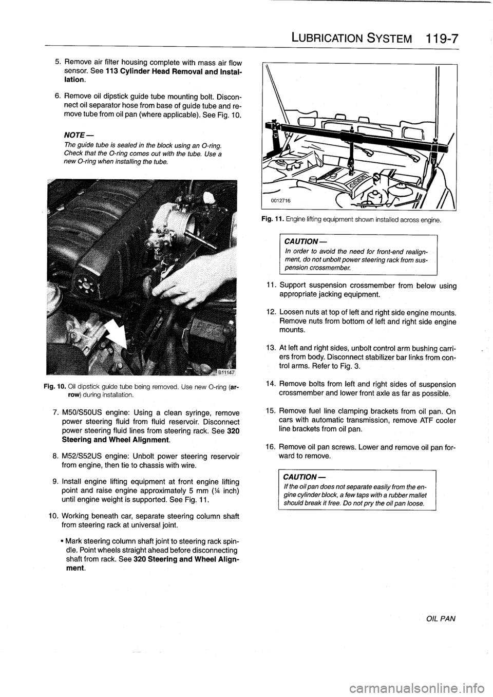
6
.
Remove
oil
dipstick
guide
tube
mounting
bolt
.
Discon-
nect
oil
separator
hose
frombase
of
guide
tube
and
re-
move
tubefrom
oil
pan
(where
applicable)
.
See
Fig
.
10
.
NOTE-
The
guide
tube
is
sealed
in
the
blockusing
an
O-ring
.
Check
that
the
O-ring
comes
out
with
the
tube
.
Use
a
new
O-ring
when
installing
the
tube
.
Fig
.
10
.
Oil
dipstick
guide
tube
being
removed
.
Use
new
O-ring
(ar-
row)
during
installation
.
7
.
M50/S50US
engine
:
Using
a
clean
syringe,
remove
power
steering
fluid
from
fluid
reservoir
.
Disconnect
power
steering
fluid
lines
from
steering
rack
.
See
320
Steering
and
Wheel
Alignment
.
8
.
M52/S52US
engine
:
Unbolt
power
steering
reservoir
from
engíne,
then
tie
to
chassis
with
wire
.
9
.
Insta¡¡
engine
lifting
equipment
atfront
engine
lifting
point
and
raise
engine
approximately
5
mm
('/a
inch)
until
engineweight
is
supported
.
See
Fig
.
11
.
10
.
Workingbeneath
car,
separate
steering
column
shaft
from
steeringrack
at
universal
joint
.
"
Mark
steering
column
shaft
jointto
steering
rack
spin-
dle
.
Point
wheels
straight
ahead
before
disconnecting
shaft
from
rack
.
See
320
Steering
and
Wheel
Align-
ment
.
LUBRICATION
SYSTEM
119
Fig
.
11
.
Engine
lifting
equipment
shown
installed
acrossengíne
.
CA
UTION-
In
order
to
avoid
the
need
for
front-end
realign-
ment,
donot
unbolt
power
steering
rack
from
sus-
pension
crossmember
.
11
.
Support
suspension
crossmember
from
below
using
appropriate
jacking
equipment
.
12
.
Loosen
nuts
at
top
of
left
and
right
side
engine
mounts
.
Remove
nuts
from
bottom
of
left
and
right
side
engine
mounts
.
13
.
At
left
and
right
sides,
unbolt
control
arm
bushíng
carri-
ers
from
body
.
Disconnect
stabilizer
bar
links
fromcon-
trol
arms
.
Refer
to
Fig
.
3
.
14
.
Remove
bolts
from
left
and
right
sides
of
suspension
crossmember
and
lower
front
axle
as
far
as
possible
.
15
.
Remove
fuelline
clamping
brackets
from
oil
pan
.
On
cars
with
automatic
transmission,
remove
ATF
cooler
line
brackets
from
oil
pan
.
16
.
Remove
oil
pan
screws
.
Lower
and
remove
oil
pan
for-
ward
to
remove
.
CA
UTION-
If
the
oil
pan
does
not
separate
easily
from
the
en-
gine
cylinder
block,
a
few
taps
with
a
rubber
mallet
shouldbreak
it
free
.
Do
notpry
the
oil
pan
loose
.
OIL
PAN
Page 125 of 759
GENERAL
.
........
.
...........
.
.
.
.
.
.
.
120-1
Camshaft
Position
(CMP)
Sensor
....
.
.
.
...
120-6
Disabling
Ignition
System
.
.
.
.
.....
.
.
.
.
.
.
.
120-2
Camshaft
position
(CMP)
sensor,
replacing
Warnings
and
Cautions
.
.
.
.
.
.
.....
.
.
.
.
.
.
.
120-2
(4-cylinder
engine)
..
.
.
.
.
.
.
.
.
.
.
.
.
.
.
.
...
120-6
Camshaft
position
(CMP)
sensor,
replacing
IGNITION
SYSTEM
DIAGNOSTICS
.
.
.
.
.
.
120-3
(6-cylinder
engine)
..
.
.
.
.
.
.
.
.
.
.
.
.
.
.
.
.
.
.
120-7
Basic
Troubleshooting
Principles
...
.
.
.
.
.
.
.
120-3
Knock
sensors,
replacing
.
.
...
.
.
.
.
.
.
.
.
.
.
.
.
120-7
Ignition
Firing
Order
.....
.
...
.
.
.
.....
.
.
.
.120-7
IGNITION
SYSTEM
SERVICE
.
.........
.
120-3
Checking
for
Spark
..
.
.
.
.
.
.
.
.
.
.......
.
.
.
120-3
Ignition
coil,
testing
and
replacing
(4-cylinder
engine)
.
.
.
.
.
.
.
.
.
.
.........
.
120-3
Ignition
coil,
testing
and
replacing
(6-cylinder
engine)
.........
.
..........
120-4
Crankshaft
Positionlrpm
Sensor
.......
.
...
120-5
Crankshaft
position/rpm
sensor,
testing
and
replacing
(front
mounted)
.........
.
.
.
.
.
.
120-6
Crankshaft
position/rpm
sensor,replacing
(rear
mounted)
.....
.
.....
.
.....
.
.
.
.
.
.
120-6
GENERAL
Troubleshooting
and
testing
of
the
engine
management
system
should
be
carried
out
using
the
BMW
specialized
ser
This
repair
group
covers
repair
andcomponent
replace-
vice
tester
(scan
tool)
.
ment
information
for
the
ignition
system
.
All
engines
use
a
distributorless
ignition
system
with
indívid-
ual
ignitioncoils
for
each
cylinder
.
There
is
no
distributor
cap
NOTE-
or
ignition
rotor
.
Each
coil
can
be
selectively
controlled
by
the
"
Spark
plug
replacement
is
covered
in
020
Mainte-
engine
control
module
on
a
cylinder-by-cylinder
basis
.
On
later
nance
Program
.
systems,
knock
sensors
are
used
to
monitor
and
control
igni-
"
For
fuel
related
troubleshooting
and
testing,
see
130
tion
knock
(ping)
and
adjusttiming
accordingly
.
Fuel
lnjection
.
Ignition
timing
is
electronically
controlled
and
not
adjust-
All
engines
covered
by
this
manual
use
an
advanced
en-
able
.
The
engine
control
module
(ECM)
usesengine
load,
en-
gine
management
system
.
The
engine
management
system
gine
speed,
coolant
temperature,
and
intake
air
temperature
incorporates
on-board
diagnostics,
fuel
injection,
ignition
and
as
the
basic
inputs
for
timing
control
.
Knock
detection
is
also
other
advanced
engine
control
functions
.
an
input
to
the
control
module,
where
applicable
.
Table
a
.
Engine
Management
System
Variants
Engine
code
1
System
4-cylinder
M42
(1.8
I)
Bosch
DME
Ml
.7
M44
(1
.9
I)
Bosch
DME
M5
.2
(OBD
II)
6-cylinder
M50
1992
(2.5
I)
Bosch
DME
M8
.1
1993-1995
(2
.5
I)
Bosch
DME
M33
.1
M52
1996-1998
(2.8
I)
Siemens
MS
41
.1
(OBD
II)
1998
(2
.5
I)
Siemens
MS
41
.1
(013D
11)
S50US
(3.0
I)
Bosch
DME
M3
.3.1
S52US
(3.2
I)
Siemens
MS
41
.1
(OBD
II)
120
Ignition
System
IGNITION
SYSTEM
120-1
IGNITION
SYSTEM
SCHEMATICS
...
.
.
.
.120-7
TABLES
a
.
Engine
Management
System
Variants
......
120-1
b
.
Ignition
Coil
Resistance
(M42
engine)
......
120-4
c
.
Ignition
Coil
Resistance
(M44
engine)
......
120-4
d
.
Ignition
Coil
Resistance
(6-cylinder
engine)
..
.
.
.
.
.
.
.
.
.
.
.
.....
.
..
120-5
NOTE-
All
engines
coveredby
this
manual,
with
theexception
of
the
1992
M50,
incorporate
knocksensors
as
part
of
the
engine
management
system
.
The
initial
ignition
point
is
determined
by
the
crankshaft
po-
sition/rpm
sensor
during
cranking
.
Once
the
engine
is
run-
ning,
timing
is
continually
adjusted
based
on
operating
conditions
.
A
characteristic
ignition
map
is
shown
in
Fig
.
1
.
A
map
similar
to
the
one
shown
is
digitally
stored
in
the
engine
control
module
.
GENERAL