BMW M4 2016 Owners Manual
Manufacturer: BMW, Model Year: 2016, Model line: M4, Model: BMW M4 2016Pages: 228, PDF Size: 4.88 MB
Page 101 of 228
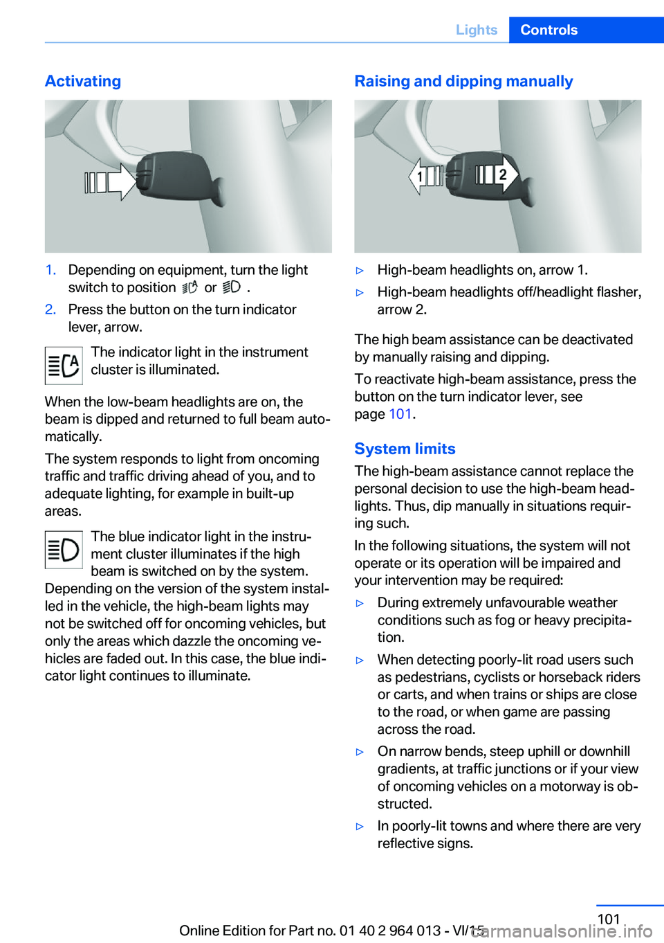
Activating1.Depending on equipment, turn the light
switch to position
or .
2.Press the button on the turn indicator
lever, arrow.
The indicator light in the instrument
cluster is illuminated.
When the low-beam headlights are on, the
beam is dipped and returned to full beam auto‐
matically.
The system responds to light from oncoming
traffic and traffic driving ahead of you, and to
adequate lighting, for example in built-up
areas.
The blue indicator light in the instru‐
ment cluster illuminates if the high
beam is switched on by the system.
Depending on the version of the system instal‐
led in the vehicle, the high-beam lights may
not be switched off for oncoming vehicles, but
only the areas which dazzle the oncoming ve‐
hicles are faded out. In this case, the blue indi‐
cator light continues to illuminate.
Raising and dipping manually▷High-beam headlights on, arrow 1.▷High-beam headlights off/headlight flasher,
arrow 2.
The high beam assistance can be deactivated
by manually raising and dipping.
To reactivate high-beam assistance, press the
button on the turn indicator lever, see
page 101.
System limits
The high-beam assistance cannot replace the
personal decision to use the high-beam head‐
lights. Thus, dip manually in situations requir‐
ing such.
In the following situations, the system will not
operate or its operation will be impaired and
your intervention may be required:
▷During extremely unfavourable weather
conditions such as fog or heavy precipita‐
tion.▷When detecting poorly-lit road users such
as pedestrians, cyclists or horseback riders
or carts, and when trains or ships are close
to the road, or when game are passing
across the road.▷On narrow bends, steep uphill or downhill
gradients, at traffic junctions or if your view
of oncoming vehicles on a motorway is ob‐
structed.▷In poorly-lit towns and where there are very
reflective signs.Seite 101LightsControls101
Online Edition for Part no. 01 40 2 964 013 - VI/15
Page 102 of 228
▷When the windscreen in front of the rear-
view mirror is covered with condensation,
dirt, stickers, labels, etc.
Fog lights
Rear fog lights
The low-beam headlights must be switched
on.
Press the button. The yellow indicator
light is illuminated.
If automatic driving lights control, see page 99,
has been activated, the low-beam headlights
come on automatically when the rear fog lights
are switched on.
Left-hand/right-hand traffic GeneralWhen driving in countries where the opposite
rule of the road applies, you need to prevent
your headlights from dazzling oncoming vehi‐
cles.
Xenon headlight
Light distribution of the headlights avoids daz‐
zling of the low-beam headlights when driving
in a country in which the traffic drives on the
opposite side.
Adaptive Headlights
When driving in a country where you drive on
the opposite side of the road from the country
the vehicle is licensed, do not drive with the
setting, otherwise this could cause a daz‐
zling effect from the variable light distribution.
LED headlights The Service Partner or a qualified specialist
workshop has light benders available. Proceed
in accordance with the enclosed information
when affixing the light benders to the head‐
lights.
Adaptive Headlights
When driving in a country where you drive on
the opposite side of the road from the country
the vehicle is licensed, do not drive with the
setting, otherwise this could cause a daz‐
zling effect from the variable light distribution.
Instrument lightingAdjusting The brightness can only be ad‐justed when the side lights or
the low-beam headlights are
switched on.
The brightness can be set using
the knurled wheel.
Interior light GeneralThe interior light, the footwell lights, door entry
lighting and the courtesy lighting are controlled
automatically.
The brightness of some equipment is influ‐
enced by the knurled wheel for the instrument
lighting.
Seite 102ControlsLights102
Online Edition for Part no. 01 40 2 964 013 - VI/15
Page 103 of 228
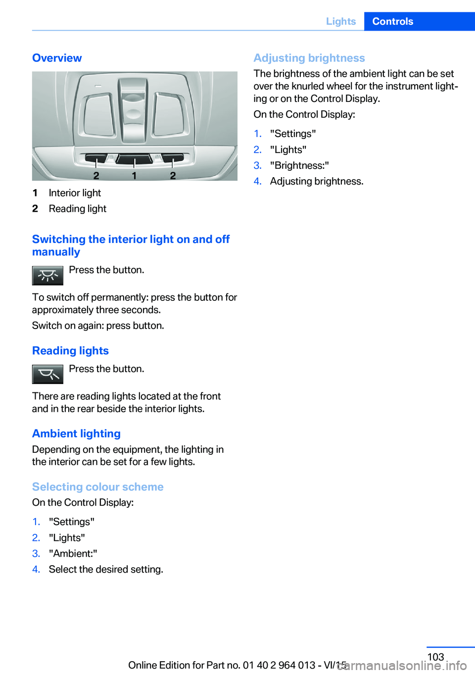
Overview1Interior light2Reading light
Switching the interior light on and off
manually
Press the button.
To switch off permanently: press the button for
approximately three seconds.
Switch on again: press button.
Reading lights Press the button.
There are reading lights located at the front
and in the rear beside the interior lights.
Ambient lighting
Depending on the equipment, the lighting in
the interior can be set for a few lights.
Selecting colour scheme
On the Control Display:
1."Settings"2."Lights"3."Ambient:"4.Select the desired setting.Adjusting brightness
The brightness of the ambient light can be set
over the knurled wheel for the instrument light‐
ing or on the Control Display.
On the Control Display:1."Settings"2."Lights"3."Brightness:"4.Adjusting brightness.Seite 103LightsControls103
Online Edition for Part no. 01 40 2 964 013 - VI/15
Page 104 of 228
SecurityVehicle equipment
This chapter describes all standard, national
and special equipment provided in the model
series. Equipment not available in the vehicle is
therefore also described, for example the se‐lected special equipment or national version.
This also applies to safety-relevant functions
and systems. Comply with the relevant na‐
tional regulations when using the correspond‐
ing functions and systems.
Airbags
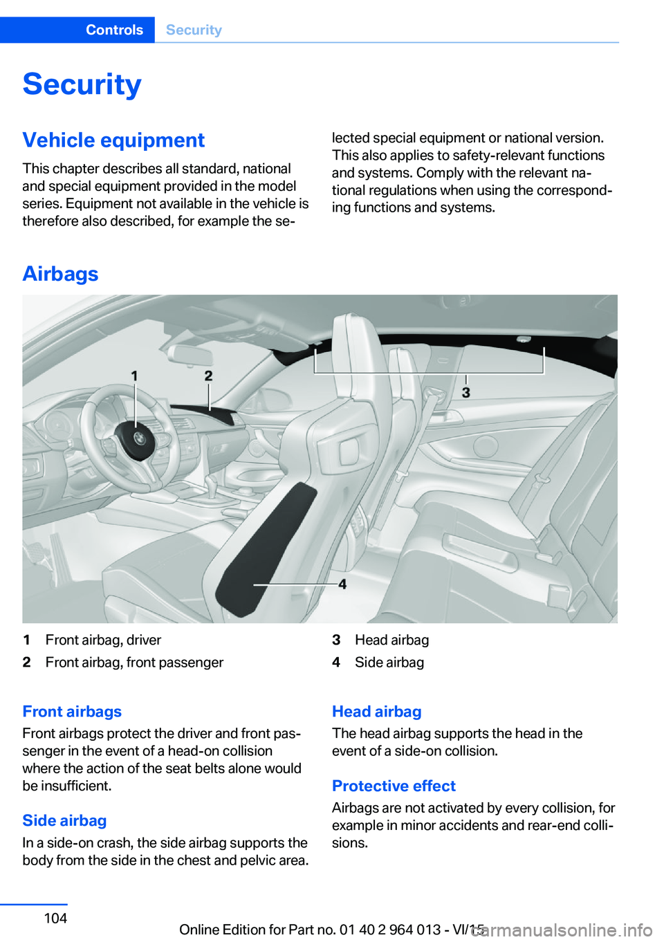
1Front airbag, driver2Front airbag, front passenger3Head airbag4Side airbagFront airbags
Front airbags protect the driver and front pas‐
senger in the event of a head-on collision
where the action of the seat belts alone would
be insufficient.
Side airbag In a side-on crash, the side airbag supports the
body from the side in the chest and pelvic area.Head airbag
The head airbag supports the head in the
event of a side-on collision.
Protective effect Airbags are not activated by every collision, for
example in minor accidents and rear-end colli‐
sions.Seite 104ControlsSecurity104
Online Edition for Part no. 01 40 2 964 013 - VI/15
Page 105 of 228
Notes on optimum protective effect of
the airbag
WARNING
If the seat position is wrong or the de‐
ployment area of the airbag is impaired, the air‐
bag system cannot provide the intended pro‐
tection, or may cause additional injuries when
it deploys. Danger of injury or life. Comply with
these notes for optimum protective effect.◀▷Keep your distance from the airbags.▷Make sure that vehicle occupants keep
their head away from the side airbag.▷Always grip the steering wheel on the
steering wheel rim. Keep you hands in the
3 o'clock and 9 o'clock positions to reduce
the risk of injury to hands or arms when the
airbag deploys.▷Make sure that the front-seat passenger is
sitting correctly, in other words with feet or
legs in the footwell, not resting on the
dashboard.▷Do not position any other persons, pets or
objects between the airbags and persons.▷Never attach any material to the airbag
covers with adhesive; never place material
over them or modify them in any way.▷Keep the dashboard and windscreen in the
area of the passenger's side free, for exam‐
ple do not attach adhesive foil or covers
and do not fit brackets for navigation devi‐
ces or mobile telephones.▷Do not use the front airbag cover on the
front passenger's side as a tray.▷Do not fit seat covers, cushions or other
objects not specifically suitable for seats
with integral side airbags to the front seats.▷Do not hang items of clothing such as
coats or jackets over the backrests.▷Do not modify individual components of
the system or its wiring in any way. This
also applies to the covers of the steering
wheel, the dashboard and seats.▷Do not dismantle the airbag system.
Even if all these notes are complied with, de‐
pending on the circumstances in which an ac‐
cident occurs, certain injuries as a result of
contact with the airbag cannot be entirely ruled
out.
The noise caused by the deployment of an air‐
bag may lead to temporary hearing loss for ve‐
hicle occupants sensitive to noise.
Operational readiness of the airbag
system
Notes WARNING
Individual components of the airbag sys‐
tem can be hot after triggering. Danger of in‐ jury. Do not touch individual components.◀
WARNING
Work carried out incorrectly can lead to a
failure, a malfunction or accidental triggering of
the airbag system. If there is a malfunction, the
airbag system might not trigger as intended in
an accident, in spite of the accident being of
the appropriate severity. Danger of injury or
life. Have the airbag system tested, repaired or
removed and scrapped by a Service Partner or a qualified specialist workshop.◀
Correct function When the ignition is switched on, the
warning light in the instrument cluster
briefly illuminates in order to show the
functional readiness of the entire airbag sys‐
tem and the belt tensioner.
Airbag system disrupted
▷Warning light does not illuminate after the
ignition is switched on.▷Warning lamp is permanently illuminated.Seite 105SecurityControls105
Online Edition for Part no. 01 40 2 964 013 - VI/15
Page 106 of 228
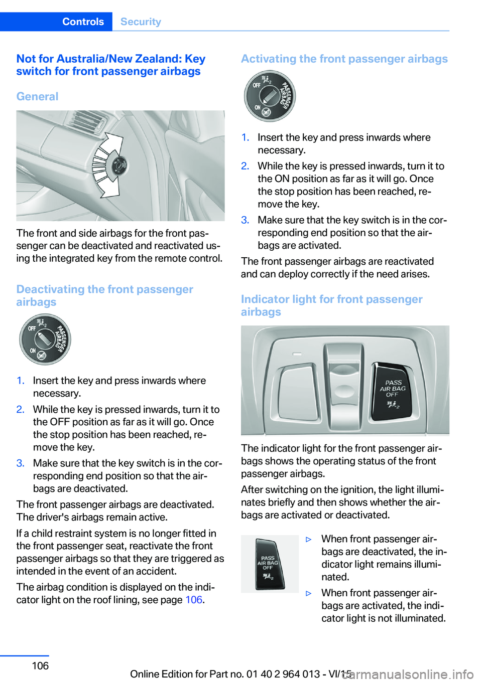
Not for Australia/New Zealand: Key
switch for front passenger airbags
General
The front and side airbags for the front pas‐
senger can be deactivated and reactivated us‐
ing the integrated key from the remote control.
Deactivating the front passenger
airbags
1.Insert the key and press inwards where
necessary.2.While the key is pressed inwards, turn it to
the OFF position as far as it will go. Once
the stop position has been reached, re‐
move the key.3.Make sure that the key switch is in the cor‐
responding end position so that the air‐
bags are deactivated.
The front passenger airbags are deactivated.
The driver's airbags remain active.
If a child restraint system is no longer fitted in
the front passenger seat, reactivate the front
passenger airbags so that they are triggered as
intended in the event of an accident.
The airbag condition is displayed on the indi‐
cator light on the roof lining, see page 106.
Activating the front passenger airbags1.Insert the key and press inwards where
necessary.2.While the key is pressed inwards, turn it to
the ON position as far as it will go. Once
the stop position has been reached, re‐
move the key.3.Make sure that the key switch is in the cor‐
responding end position so that the air‐
bags are activated.
The front passenger airbags are reactivated
and can deploy correctly if the need arises.
Indicator light for front passenger airbags
The indicator light for the front passenger air‐
bags shows the operating status of the front
passenger airbags.
After switching on the ignition, the light illumi‐
nates briefly and then shows whether the air‐
bags are activated or deactivated.
▷When front passenger air‐
bags are deactivated, the in‐
dicator light remains illumi‐
nated.▷When front passenger air‐
bags are activated, the indi‐
cator light is not illuminated.Seite 106ControlsSecurity106
Online Edition for Part no. 01 40 2 964 013 - VI/15
Page 107 of 228
Tyre Pressure Monitor TPM
Principle The system monitors the tyre pressure in the
four fitted tyres. The system warns if the infla‐
tion pressure in one or more tyres has fallen
considerably. To do this, the sensors in the
tyre valves measure the tyre pressure and tyre
temperatures.
Note
To operate the system, also follow the other
information and notes under tyre inflation pres‐
sure, see page 175.
Operating requirements For the system, a reset must have been made
with the correct tyre inflation pressure, other‐
wise reliable signalling of a flat tyre cannot be assured.
Reset the system after adjusting the tyre pres‐
sure to a new value and after a tyre or wheel
change.
Always use wheels with TPM electronics to
guarantee the system functions without errors.
Status display
The current status of the Tyre Pressure Moni‐
tor TPM can be shown on the Control Display,
for example whether the TPM is active.
On the Control Display:1."Vehicle information"2."Vehicle status"3. "Tyre Pressure Monitor (RDC)"
The status is displayed.
Status control display The tyre and system status is denoted by the
wheel colour and some text on the Control Dis‐
play.
All wheels green
System is active and is warning about the tyre
inflation pressures stored during the last reset.
One wheel yellow
A flat tyre or major loss of tyre inflation pres‐
sure in the tyre shown.
All wheels yellow
A flat tyre or major loss of tyre inflation pres‐
sure in several tyres.
Wheels grey
The system cannot detect a flat tyre. The rea‐
sons for this are:▷System reset is performed.▷Malfunction.
Additional information
The current tyre inflation pressures and, de‐
pending on the model, tyre temperatures are
also displayed in the status control display.
The values shown are current values and may
change due to the effect of driving mode or
weather conditions.
Running reset Reset the system after adjusting the tyre pres‐
sure to a new value and after a tyre or wheel
change.
On the Control Display and on the vehicle:
1."Vehicle information"2."Vehicle status"3. "Perform reset"4.Start the engine – do not drive off.5.Resetting tyre pressure: "Perform reset".6.Drive off.
The wheels are shown grey and the status ap‐
pears on the display.
After driving for a short time over 30 km/h,
19 mph the set tyre inflation pressures are ac‐
Seite 107SecurityControls107
Online Edition for Part no. 01 40 2 964 013 - VI/15
Page 108 of 228
cepted as target values. The reset is run auto‐
matically while the vehicle is in motion.
After a successfully concluded reset, the
wheels are shown in green on the Control Dis‐
play and "Tyre Pressure Monitor (RDC)
active." is shown.
You can interrupt your drive at any time. Reset
resumes automatically when you continue
your journey.
Message if tyre inflation pressure is
low
The yellow warning lamp is illuminated.
A Check Control message is shown.▷There is a flat tyre or substantial
loss of tyre pressure.▷No reset has been done to the system.
Consequently, the system warns of the
tyre pressures of the last reset.1.Reduce your speed and carefully stop the
vehicle. Avoid violent or sudden braking
and steering manoeuvres.2.Determine which wheel is damaged. Do
this by checking the tyre inflation pres‐
sures with the aid of the Mobility System.
Correcting the tyre inflation pressure3.Remedy the flat tyre with the Mobility Sys‐
tem or replace the damaged wheel.
When there is a message that the tyre inflation
pressure is low, the Dynamic Stability Control
DSC may be switched on.
Message with required tyre inflation
pressure test
In such situations, a check control message is
displayed:
▷System has detected a wheel change, but
no reset has been run.▷Filling was not performed according to the
regulations.▷The tyre inflation pressure has dropped
compared to the last confirmation.If that is the case:▷Check the tyre pressure and adjust as nec‐
essary.▷Reset the system after a wheel change.
System limits
The system is not working correctly if no reset
has been run, for example, a flat tyre is repor‐
ted in spite of the correct tyre inflation pres‐
sure.
Tyre inflation pressure depends on the tem‐
perature of the tyre. By increasing tyre temper‐
ature, for example, when driving or with solar
radiation, the tyre inflation pressure increases.
Tyre inflation pressure decreases if the tyre
temperature drops. Through this behaviour, a
warning may be triggered if there are major
temperature drops, due to the given warning
limits.
No warning can be given by the system of ex‐
treme, sudden tyre failure caused by external
factors.
Malfunction The yellow warning lamp flashes and is
then illuminated continuously. A Check
Control message is shown. No flat
tyres or loss of tyre pressure can be detected.
This may indicate one of the following:
▷Wheel without TPM electronics is fitted:
have the vehicle checked by a Service
Partner or a qualified specialist workshop if
necessary.▷Malfunction: have the system checked by a
Service Partner or a qualified specialist
workshop.▷TPM has not completed a reset. Run a re‐
set of the system again.▷Fault due to systems or devices with the
same frequency: the system is automati‐
cally reactivated upon leaving the field of
interference.Seite 108ControlsSecurity108
Online Edition for Part no. 01 40 2 964 013 - VI/15
Page 109 of 228
Runflat indicator RPA
Principle The system identifies a loss of tyre pressure
by comparing the speeds of rotation of the in‐
dividual wheels while the vehicle is in motion.
If a tyre loses pressure, its diameter changes.
This in turn alters the rotational speed of the
corresponding wheel. This is detected and re‐
ported as a flat tyre.
The system does not measure the tyre pres‐
sures as such.
Operating requirements
The system must have been initialised with
correct tyre inflation pressure, otherwise relia‐
ble signalling of a flat tyre cannot be assured.
Each time the tyre pressure is adjusted or a
tyre or wheel is changed, initialise the system
again.
Status display The current status of the runflat indicator can
be shown on the Control Display, for example
whether the runflat indicator is active.
On the Control Display:1."Vehicle information"2."Vehicle status"3. "Flat Tyre Monitor (RPA)"
The status is displayed.
Initialising
On initialisation, the current tyre pressures are
stored as a reference for detection of a flat tyre. The initialisation is started by confirming
the correct tyre inflation pressures.
When driving with snow chains fitted, do not
initialise the system.
On the Control Display:
1."Vehicle information"2."Vehicle status"3. "Perform reset"4.Start the engine – do not drive off.5.Start the initialisation with "Perform reset".6.Drive off.
Initialising is completed while the vehicle is in
motion; this process can be interrupted at any
time.
Initialising resumes automatically when you
continue your journey.
Message of a flat tyre The yellow warning lamp is illuminated.
A Check Control message is shown.
There is a flat tyre or substantial loss of
tyre pressure.
1.Reduce your speed and carefully stop the
vehicle. Avoid violent or sudden braking
and steering manoeuvres.2.Determine which wheel is damaged. Do
this by checking the tyre inflation pres‐
sures with the aid of the Mobility System. If
all tyres are inflated to the correct pres‐
sures, the runflat indicator might not have
been initialised. In this case initialise the
system.3.Remedy the flat tyre with the Mobility Sys‐
tem or replace the damaged wheel.
System limits
A natural, even loss of tyre pressurein all four
tyres that occurs over time is not detected.
Consequently, check the tyre inflation pres‐
sure at regular intervals.
No warning can be given in the event of sud‐
den tyre failure caused by external factors.
In the following situations, the system could be
slow to respond or operate incorrectly:
▷If the system has not been initialised.▷Journey on snow-covered or slippery sur‐
faces.Seite 109SecurityControls109
Online Edition for Part no. 01 40 2 964 013 - VI/15
Page 110 of 228
▷Dynamic driving style, causing the drive
gears to spin, high lateral acceleration.▷Driving with snow chains.
Intelligent Safety
Principle
Intelligent Safety permits central operation of
driver assistance systems.
Depending on equipment, Intelligent Safety
consists of one or more systems which can
help to avoid the risk of a collision. These sys‐
tems are automatically active each time you
start the engine with the start/stop button:
▷Front-end collision warning with city brak‐
ing function, see page 111.▷Person warning, see page 113.
Notes
WARNING
Displays and warnings do not take your
personal responsibility from you. System limi‐
tations can mean that warnings or system re‐
sponses are not issued, are issued too late, or are issued incorrectly. Danger of accidents.
Adapt driving style to the driving conditions.
Observe the traffic situation and intervene ac‐
tively if the situation warrants it.◀
WARNING
Due to system limitations, there may be
malfunctions of individual functions when tow-
starting/towing with activated Intelligent Safety Systems, for example approach control warn‐
ing with light braking function. Danger of acci‐
dents. Switch off all Intelligent Safety Systems
before tow-starting/towing.◀
Overview
Button in the vehicle
Intelligent Safety button
Camera
The camera is in the area of the base of the
rear-view mirror.
Keep the windscreen clean and clear in the
area in front of the rear view mirror.
Switching on/offThe Intelligent Safety Systems are active auto‐
matically at the start of each journey.
Press button: the systems are
switched off again. LED turns off.
Press button again: the systems are switched
on. LED is illuminated.
Settings can be adjusted on the Control Dis‐
play.
Seite 110ControlsSecurity110
Online Edition for Part no. 01 40 2 964 013 - VI/15