BMW M4 2016 Repair Manual
Manufacturer: BMW, Model Year: 2016, Model line: M4, Model: BMW M4 2016Pages: 228, PDF Size: 4.88 MB
Page 61 of 228
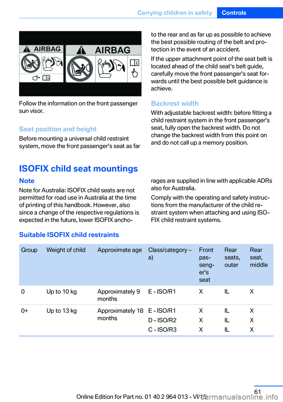
Follow the information on the front passenger
sun visor.
Seat position and height
Before mounting a universal child restraint
system, move the front passenger's seat as far
to the rear and as far up as possible to achieve
the best possible routing of the belt and pro‐
tection in the event of an accident.
If the upper attachment point of the seat belt is
located ahead of the child seat's belt guide,
carefully move the front passenger's seat for‐
wards until the best possible belt guidance is
achieve.
Backrest width With adjustable backrest width: before fitting a
child restraint system in the front passenger's
seat, fully open the backrest width. Do not
change the backrest width from this point on
and do not call up a memory position.
ISOFIX child seat mountings
Note
Note for Australia: ISOFIX child seats are not
permitted for road use in Australia at the time
of printing of this handbook. However, also
since a change of the respective regulations is
expected in the future, lower ISOFIX ancho‐rages are supplied in line with applicable ADRs
also for Australia.
Comply with the operating and safety instruc‐
tions from the manufacturer of the child re‐
straint system when attaching and using ISO‐
FIX child restraint systems.
Suitable ISOFIX child restraints
GroupWeight of childApproximate ageClass/category –
a)Front
pas‐
seng‐
er's
seatRear
seats,
outerRear
seat,
middle0Up to 10 kgApproximately 9
monthsE - ISO/R1XILX0+Up to 13 kgApproximately 18
monthsE - ISO/R1
D - ISO/R2
C - ISO/R3X
X
XIL
IL
ILX
X
XSeite 61Carrying children in safetyControls61
Online Edition for Part no. 01 40 2 964 013 - VI/15
Page 62 of 228
GroupWeight of childApproximate ageClass/category –
a)Front
pas‐
seng‐
er's
seatRear
seats,
outerRear
seat,
middleI9 - 18 kgUp to approxi‐
mately 4 yearsD - ISO/R2
C - ISO/R3
B - ISO/F2
B1 - ISO/F2X
A - ISO/F3X
X
X
X
XIL
IL
IL, IUF
IL, IUF
IL, IUFX
X
X
X
XIL: the seat is suitable for installation of an ISOFIX child seat in the Semi-Universal category sub‐
ject to compliance with the list of vehicles accompanying the child seat.IUF: the seat is suitable for installation of an ISOFIX child seat with Universal approval and at‐
tachment with the TOP TETHER strap.X: the seat is not approved or equipped with mounting points for the ISOFIX system.a) When using child seats on the rear seats, adapt the front/back position of the front seat if nec‐
essary, and also adjust the head restraint of the rear seat, or remove it.Brackets for lower ISOFIX anchors
Information WARNING
If the ISOFIX child restraint systems are
not engaged correctly, the protective effect of
the ISOFIX child restraint systems may be re‐
stricted. Danger of injury or life. Make sure the
lower anchor point has engaged correctly and
the ISOFIX child restraint system is firmly posi‐
tioned against the backrest.◀
Position The corresponding symbol shows the
brackets for the lower ISOFIX anchor
points.
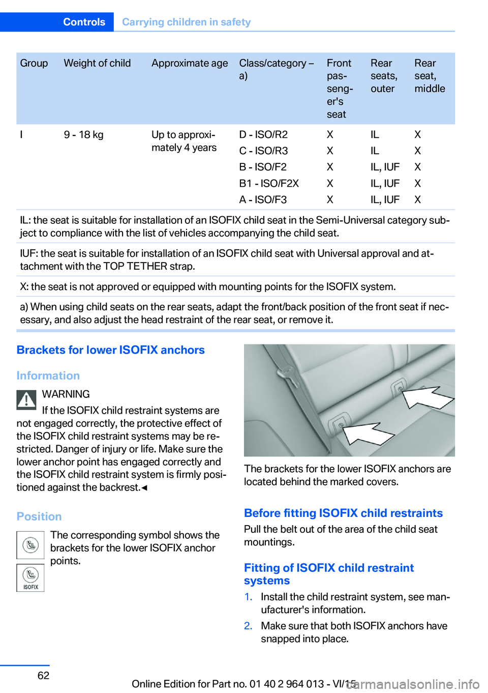
The brackets for the lower ISOFIX anchors are
located behind the marked covers.
Before fitting ISOFIX child restraints
Pull the belt out of the area of the child seat
mountings.
Fitting of ISOFIX child restraint
systems
1.Install the child restraint system, see man‐
ufacturer's information.2.Make sure that both ISOFIX anchors have
snapped into place.Seite 62ControlsCarrying children in safety62
Online Edition for Part no. 01 40 2 964 013 - VI/15
Page 63 of 228
Upper ISOFIX retaining strap
Mounting points The symbol shows the mounting point
for the upper retaining strap.
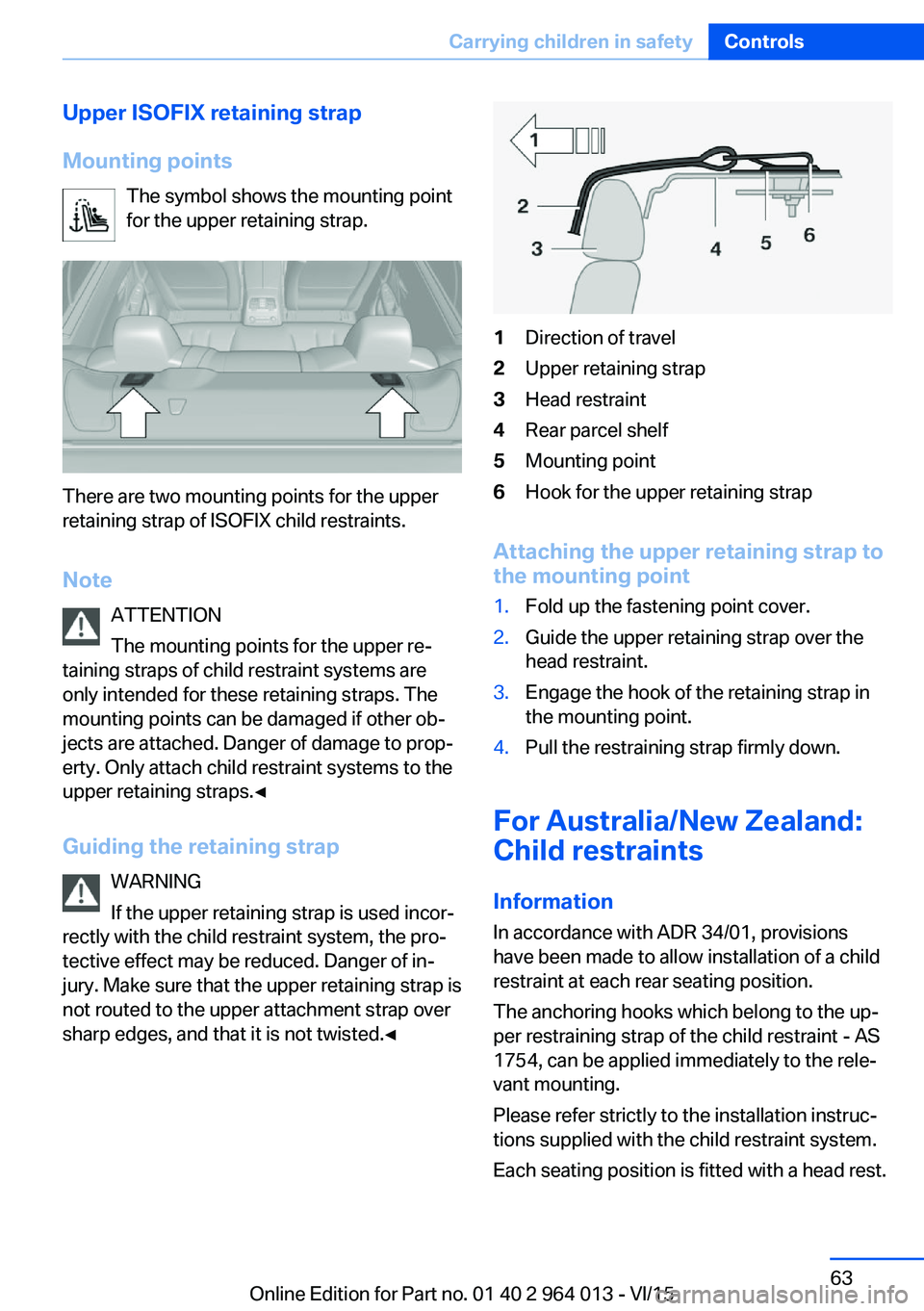
There are two mounting points for the upper
retaining strap of ISOFIX child restraints.
Note ATTENTION
The mounting points for the upper re‐
taining straps of child restraint systems are
only intended for these retaining straps. The
mounting points can be damaged if other ob‐
jects are attached. Danger of damage to prop‐
erty. Only attach child restraint systems to the
upper retaining straps.◀
Guiding the retaining strap WARNING
If the upper retaining strap is used incor‐
rectly with the child restraint system, the pro‐
tective effect may be reduced. Danger of in‐
jury. Make sure that the upper retaining strap is
not routed to the upper attachment strap over
sharp edges, and that it is not twisted.◀
1Direction of travel2Upper retaining strap3Head restraint4Rear parcel shelf5Mounting point6Hook for the upper retaining strap
Attaching the upper retaining strap to
the mounting point
1.Fold up the fastening point cover.2.Guide the upper retaining strap over the
head restraint.3.Engage the hook of the retaining strap in
the mounting point.4.Pull the restraining strap firmly down.
For Australia/New Zealand:
Child restraints
Information
In accordance with ADR 34/01, provisions
have been made to allow installation of a child
restraint at each rear seating position.
The anchoring hooks which belong to the up‐
per restraining strap of the child restraint - AS
1754, can be applied immediately to the rele‐
vant mounting.
Please refer strictly to the installation instruc‐
tions supplied with the child restraint system.
Each seating position is fitted with a head rest.
Seite 63Carrying children in safetyControls63
Online Edition for Part no. 01 40 2 964 013 - VI/15
Page 64 of 228
WARNING
Child restraint anchorages are designed
to withstand only those loads imposed by cor‐
rectly fitted child restraints. Under no circum‐
stances are they to be used for adult seat
belts, harnesses or for attaching other items or
equipment to the vehicle. After using the child
restraints, the anchor fittings may need to be
folded down.◀
Mounting points The symbol shows the mounting point
for the upper retaining strap.
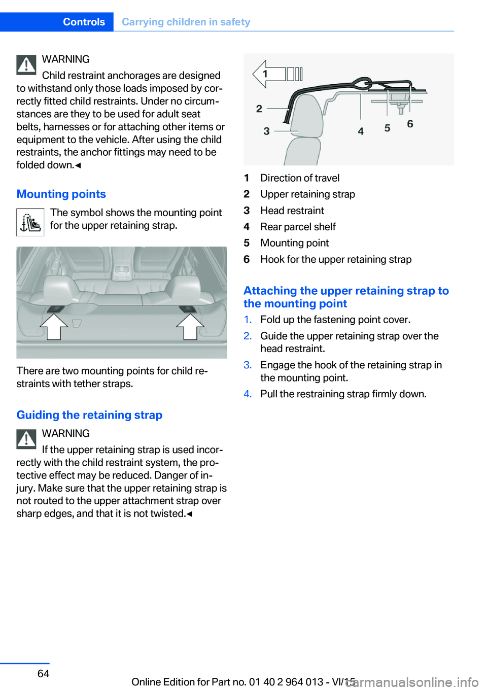
There are two mounting points for child re‐
straints with tether straps.
Guiding the retaining strap WARNING
If the upper retaining strap is used incor‐
rectly with the child restraint system, the pro‐
tective effect may be reduced. Danger of in‐
jury. Make sure that the upper retaining strap is
not routed to the upper attachment strap over
sharp edges, and that it is not twisted.◀
1Direction of travel2Upper retaining strap3Head restraint4Rear parcel shelf5Mounting point6Hook for the upper retaining strap
Attaching the upper retaining strap to
the mounting point
1.Fold up the fastening point cover.2.Guide the upper retaining strap over the
head restraint.3.Engage the hook of the retaining strap in
the mounting point.4.Pull the restraining strap firmly down.Seite 64ControlsCarrying children in safety64
Online Edition for Part no. 01 40 2 964 013 - VI/15
Page 65 of 228
DrivingVehicle equipment
This chapter describes all standard, national
and special equipment provided in the model
series. Equipment not available in the vehicle is
therefore also described, for example the se‐
lected special equipment or national version.
This also applies to safety-relevant functions
and systems. Comply with the relevant na‐
tional regulations when using the correspond‐
ing functions and systems.
Start/stop button
Principle The ignition is switched on or offand the engine is started by
pressing the start/stop button.
M double clutch transmission:
The engine starts if the brakes
are applied when the start-stop button is
pressed.
Manual gearbox: The engine starts if the clutch
pedal is pressed when pressing the start/stop
button.
Ignition on M double clutch transmission: Press the start/
stop button without applying the brakes.
Manual gearbox: Press the start/stop button,
do not press the clutch pedal.
All systems are operational.
Most of the indicator and warning lamps in the
instrument cluster are illuminated for different
lengths of time.
To save battery power when the engine is off,
switch off the ignition and any unnecessary
electronic systems.Ignition off
M double clutch transmission: Press the start/
stop button again without applying the brakes.
Manual gearbox: Press the start/stop button
again, do not press the clutch pedal.
All indicator lights in the instrument cluster ex‐
tinguish.
To save battery power when the engine is off,
switch off the ignition and any unnecessary
electronic systems.
Notes
When the ignition is switched off, selector
lever position P will be automatically engaged,
if selector lever position D or R is engaged.
With the vehicle stationary and the engine shut
down, the ignition is switched off automatically
under the following circumstances:▷When locking, even with the low-beam
headlights switched on.▷Shortly before the battery is discharged so
that an engine start remains possible.▷When opening or closing the driver's door,
if the driver's belt is unfastened and the
low-beam headlights are switched off.▷When the driver's belt is unfastened, if the
driver's door is opened and the low-beam
headlights switched off.
After about 15 minutes without further opera‐
tion, low-beam headlights are changed over to
side lights.
Radio ready state
Activate radio ready state: when the engine is
running, press the start/stop button.
Individual electrical systems remain opera‐
tional.
The radio ready sate is automatically switched
off in the following situations:
Seite 65DrivingControls65
Online Edition for Part no. 01 40 2 964 013 - VI/15
Page 66 of 228
▷After approximately eight minutes.▷When locking via the central locking sys‐
tem.▷Shortly before the battery is discharged so
that an engine start remains possible.
Radio readiness remains active when ignition
is switched off automatically, such as for
following reasons:
▷Opening or closing driver's door.▷Unfastening driver's seat belt.▷When low-beam headlights are automati‐
cally changed to side lights.
If engine is switched off and ignition is
switched on, radio ready state will be automati‐
cally activated when door is opened if light is
switched off or daytime driving lights are
switched on, when corresponding equipment
is fitted.
Engine start Notes DANGER
A blocked exhaust pipe or inadequate
ventilation can allow harmful exhaust fumes to
penetrate the vehicle. The exhaust gas con‐
tains carbon monoxide, which is colourless and
odourless, but highly toxic. In enclosed spaces,
the exhaust fumes can also build up outside
the vehicle. Danger of fatal injury. Keep the ex‐
haust pipe clear and ensure sufficient ventila‐
tion.◀
WARNING
An unsecured vehicle can start moving
and rolling away. Danger of accidents. Before
leaving the vehicle, secure it to prevent rolling
away.
Observe the following to ensure that the vehi‐
cle is secured against rolling away:
▷Engage the parking brake.▷Turn the front wheels into the direction of
the kerb on upward or downward gradi‐
ents.▷Additionally secure the vehicle on upward
or downward gradients, e.g. using a
wedge.◀
ATTENTION
Repeated start attempts or starting sev‐
eral times in quick succession means that fuel
is not combusted, or insufficiently so. The cat‐
alytic converter can overheat. Danger of dam‐
age to property. Avoid starting more than once
in quick succession.◀
M double clutch transmission
Starting the engine
1.Press the brake.2.Press the start/stop button.
Starting proceeds for a certain time automati‐
cally and stops as soon as the engine is star‐
ted.
Manual gearbox
Starting the engine
1.Press the brake.2.Depress the clutch and engage idle posi‐
tion.3.Press the start/stop button.
Starting proceeds for a certain time automati‐
cally and stops as soon as the engine is star‐
ted.
Seite 66ControlsDriving66
Online Edition for Part no. 01 40 2 964 013 - VI/15
Page 67 of 228
Stopping the engine
Notes WARNING
Unsupervised children or animals in the
vehicle can set the vehicle in motion and en‐
danger themselves or other road users, for ex‐
ample by the following actions:▷Pressing the start/stop button.▷Releasing the parking brake.▷Opening and closing doors or windows.▷Setting the selector lever to neutral.▷Operating vehicle equipment.
Risk of accident or injury. Do not leave children
or animals unsupervised in the vehicle. When
leaving the vehicle, take the remote control
with you and lock it.◀
WARNING
An unsecured vehicle can start moving
and rolling away. Danger of accidents. Before
leaving the vehicle, secure it to prevent rolling
away.
Observe the following to ensure that the vehi‐
cle is secured against rolling away:
▷Engage the parking brake.▷Turn the front wheels into the direction of
the kerb on upward or downward gradi‐
ents.▷Additionally secure the vehicle on upward
or downward gradients, e.g. using a
wedge.◀
Before entering the car wash
So that the vehicle can roll into the vehicle
wash, follow the information on washing in au‐
tomatic vehicle washes, see page 208.
M double clutch transmission
Stopping the engine
1.Brake the vehicle until it comes to a stop.2.Press the start/stop button.
The engine is switched off.
The radio ready state is switched on.3.Apply the parking brake.
Manual gearbox
Stopping the engine
1.Press the Start/Stop button when the vehi‐
cle is at standstill.2.Engage first gear or reverse.3.Apply the parking brake.
Auto Start Stop function
Principle The Auto Start Stop function helps you to save
fuel. by stopping the engine when stationary,
for example, in a traffic jam or at traffic lights.
The ignition remains switched on. For driving
off, the engine starts automatically.
Automatic operation
After each time the engine is started using the
start/stop button, the Auto Start Stop function
is ready to operate.
The function is activated from 5 km/h,
3 mph3 mph, km/h.
Stopping the engine The engine is automatically shut down whenstationary under the following conditions:
M double clutch transmission:
▷Selector lever in selector lever position D.▷Brake pedal remains depressed while the
vehicle is at a standstill.▷Driver's seat belt buckled or driver's door
closed.
Manual gearbox:
▷Transmission in neutral and clutch pedal
not pressed.Seite 67DrivingControls67
Online Edition for Part no. 01 40 2 964 013 - VI/15
Page 68 of 228
▷Driver's seat belt buckled or driver's door
closed.
The air flow rate of the air conditioning system
is reduced when the engine is not running.
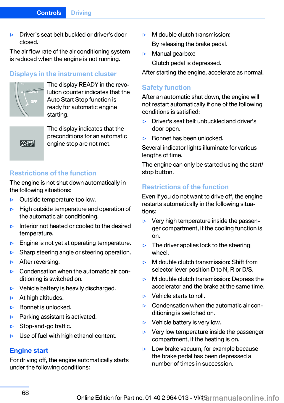
Displays in the instrument cluster The display READY in the revo‐
lution counter indicates that the
Auto Start Stop function is
ready for automatic engine
starting.
The display indicates that the preconditions for an automatic
engine stop are not met.
Restrictions of the function The engine is not shut down automatically in
the following situations:
▷Outside temperature too low.▷High outside temperature and operation of
the automatic air conditioning.▷Interior not heated or cooled to the desired
temperature.▷Engine is not yet at operating temperature.▷Sharp steering angle or steering operation.▷After reversing.▷Condensation when the automatic air con‐
ditioning is switched on.▷Vehicle battery is heavily discharged.▷At high altitudes.▷Bonnet is unlocked.▷Parking assistant is activated.▷Stop-and-go traffic.▷Use of fuel with high ethanol content.
Engine start
For driving off, the engine automatically starts
under the following conditions:
▷M double clutch transmission:
By releasing the brake pedal.▷Manual gearbox:
Clutch pedal is depressed.
After starting the engine, accelerate as normal.
Safety function After an automatic shut down, the engine will
not restart automatically if one of the following
conditions is satisfied:
▷Driver's seat belt unbuckled and driver's
door open.▷Bonnet has been unlocked.
Several indicator lights illuminate for various
lengths of time.
The engine can only be started using the start/
stop button.
Restrictions of the function
Even if you do not want to drive off, the engine
restarts automatically in the following situa‐
tions:
▷Very high temperature inside the passen‐
ger compartment, if the cooling function is
on.▷The driver applies lock to the steering
wheel.▷M double clutch transmission: Shift from
selector lever position D to N, R or D/S.▷M double clutch transmission: Depress the
accelerator and the brake at the same time.▷Vehicle starts to roll.▷Condensation when the automatic air con‐
ditioning is switched on.▷Vehicle battery is very low.▷Very low temperature inside the passenger
compartment, if the heating is on.▷Low brake vacuum, for example because
the brake pedal has been depressed a
number of times in succession.Seite 68ControlsDriving68
Online Edition for Part no. 01 40 2 964 013 - VI/15
Page 69 of 228
Preventing automatic engine stop
with M double clutch transmission
Principle To enable the vehicle to move off particularly
swiftly, for example at a junction, the automatic
engine stop can be actively prevented.
Preventing automatic engine stop
using the brake pedal
The engine stop can be actively prevented
within a second of the vehicle coming to a
standstill:▷Press the brake pedal down firmly as soon
as the vehicle has come to a standstill.▷Then immediately brake again with normal
braking force.
Manually deactivating/activating the
system
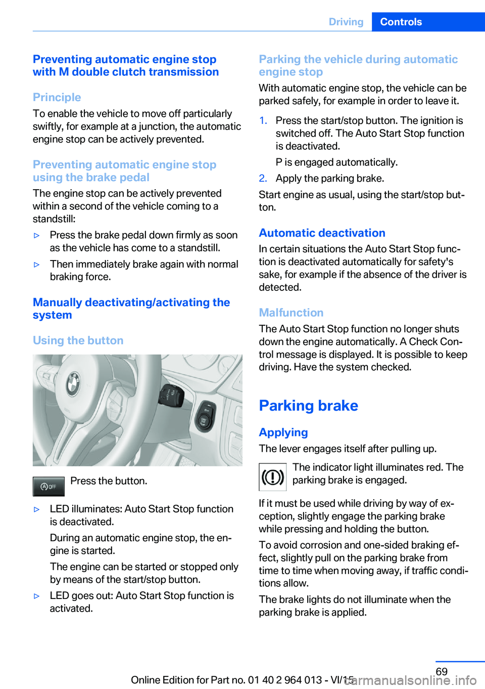
Using the button
Press the button.
▷LED illuminates: Auto Start Stop function
is deactivated.
During an automatic engine stop, the en‐
gine is started.
The engine can be started or stopped only
by means of the start/stop button.▷LED goes out: Auto Start Stop function is
activated.Parking the vehicle during automatic
engine stop
With automatic engine stop, the vehicle can be
parked safely, for example in order to leave it.1.Press the start/stop button. The ignition is
switched off. The Auto Start Stop function
is deactivated.
P is engaged automatically.2.Apply the parking brake.
Start engine as usual, using the start/stop but‐
ton.
Automatic deactivation
In certain situations the Auto Start Stop func‐
tion is deactivated automatically for safety's
sake, for example if the absence of the driver is
detected.
Malfunction
The Auto Start Stop function no longer shuts
down the engine automatically. A Check Con‐
trol message is displayed. It is possible to keep
driving. Have the system checked.
Parking brake
Applying The lever engages itself after pulling up.
The indicator light illuminates red. The
parking brake is engaged.
If it must be used while driving by way of ex‐
ception, slightly engage the parking brake
while pressing and holding the button.
To avoid corrosion and one-sided braking ef‐
fect, slightly pull on the parking brake from
time to time when moving away, if traffic condi‐
tions allow.
The brake lights do not illuminate when the
parking brake is applied.
Seite 69DrivingControls69
Online Edition for Part no. 01 40 2 964 013 - VI/15
Page 70 of 228
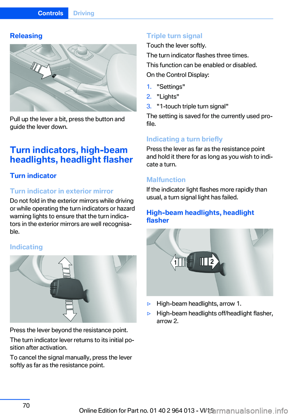
Releasing
Pull up the lever a bit, press the button and
guide the lever down.
Turn indicators, high-beam
headlights, headlight flasher
Turn indicator
Turn indicator in exterior mirror
Do not fold in the exterior mirrors while driving
or while operating the turn indicators or hazard
warning lights to ensure that the turn indica‐
tors in the exterior mirrors are well recognisa‐
ble.
Indicating
Press the lever beyond the resistance point.
The turn indicator lever returns to its initial po‐
sition after activation.
To cancel the signal manually, press the lever
softly as far as the resistance point.
Triple turn signal
Touch the lever softly.
The turn indicator flashes three times.
This function can be enabled or disabled.
On the Control Display:1."Settings"2."Lights"3."1-touch triple turn signal"
The setting is saved for the currently used pro‐
file.
Indicating a turn briefly
Press the lever as far as the resistance point
and hold it there for as long as you wish to indi‐
cate a turn.
Malfunction
If the indicator light flashes more rapidly than
usual, a turn signal light has failed.
High-beam headlights, headlight
flasher
▷High-beam headlights, arrow 1.▷High-beam headlights off/headlight flasher,
arrow 2.Seite 70ControlsDriving70
Online Edition for Part no. 01 40 2 964 013 - VI/15