BMW MOTORRAD C1 2000 Rider's Manual (in English)
C1 2000
BMW MOTORRAD
BMW MOTORRAD
https://www.carmanualsonline.info/img/47/38011/w960_38011-0.png
BMW MOTORRAD C1 2000 Rider's Manual (in English)
Trending: check engine, warning lights, fuel, warning light, parking brake, oil level, automatic transmission
Page 11 of 96
111
9
General information and controls
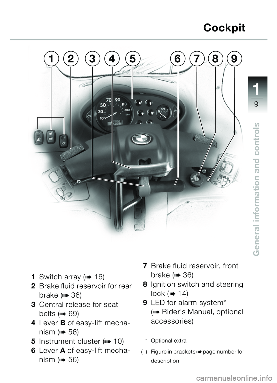
1Switch array (b16)
2 Brake fluid reservoir for rear
brake (
b36)
3 Central release for seat
belts (
b69)
4 Lever B of easy-lift mecha-
nism (
b56)
5 Instrument cluster (
b10)
6 Lever A of easy-lift mecha-
nism (
b56) 7
Brake fluid reservoir, front
brake (
b36)
8 Ignition switch and steering
lock (
b14)
9 LED for alarm system*
(
bRider's Manual, optional
accessories)
* Optional extra
( ) Figure in brackets
bpage number for
description
Cockpit
567824319
�� �
Page 12 of 96
11
10
General information and controls
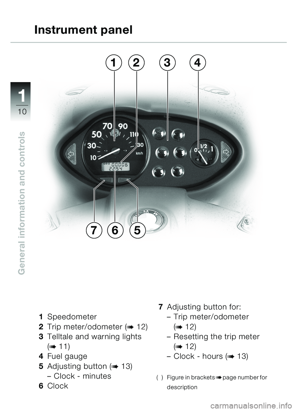
1Speedometer
2 Trip meter/odometer (
b12)
3 Telltale and warning lights
(
b11)
4 Fuel gauge
5 Adjusting button (
b13)
– Clock - minutes
6 Clock 7
Adjusting button for:
–Trip meter/odometer
(
b12)
– Resetting the trip meter
(
b12)
– Clock - hours (
b13)
( ) Figure in bracketsbpage number for
description
Instrument panel
657
3142
�� �
Page 13 of 96
111
11
General information and controls
13476
9
5
8
2
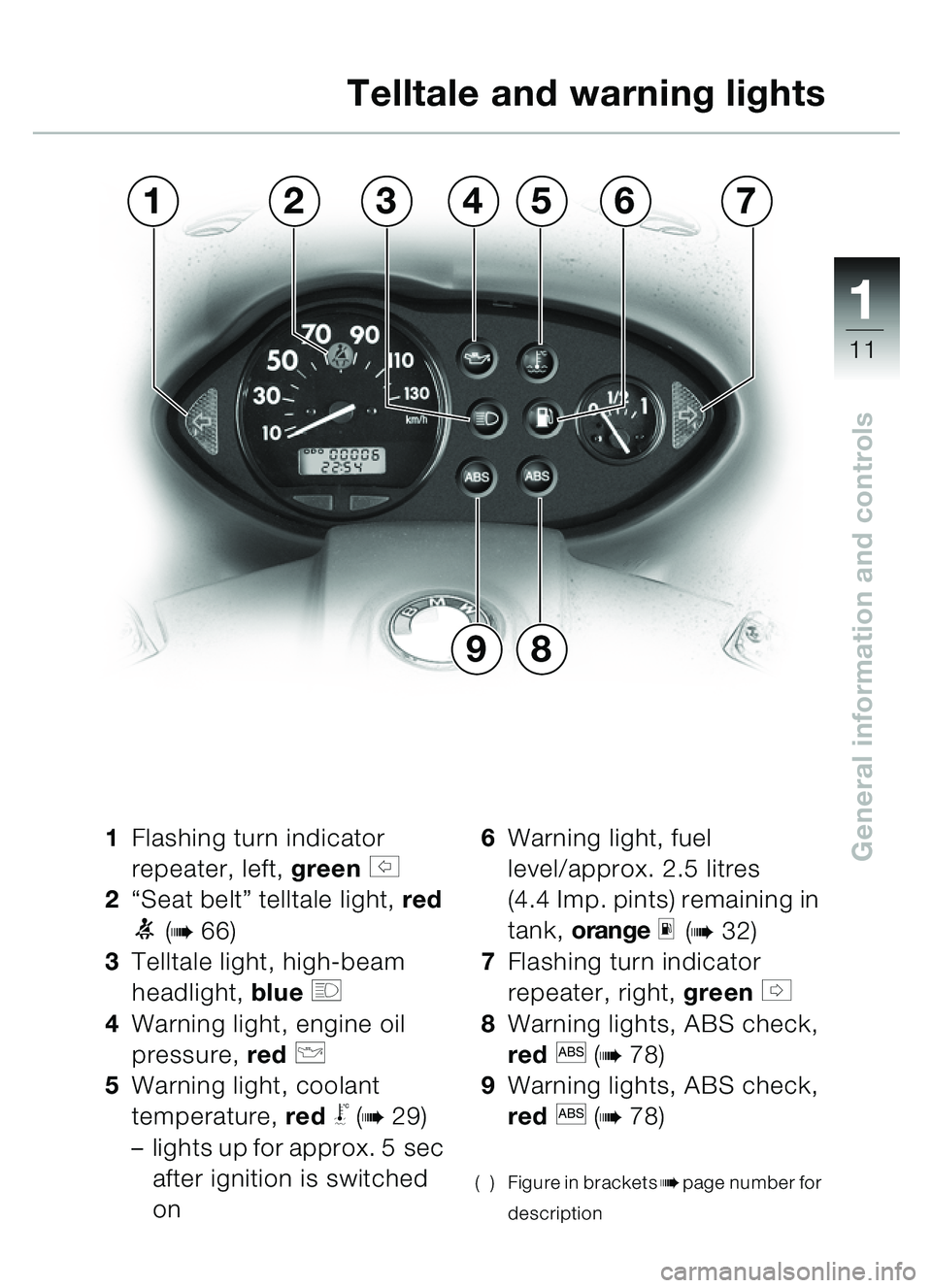
1Flashing turn indicator
repeater, left, green
s
2 “Seat belt ” telltale light, red
1 (b66)
3 Telltale light, high-beam
headlight, blue
q
4 Warning light, engine oil
pressure, red
p
5Warning light, coolant
temperature, red
\b (b29)
– lights up for approx. 5 sec
after ignition is switched
on 6
Warning light, fuel
level/approx. 2.5 litres
(4.4 Imp. pints) remaining in
tank, orange
m (b32)
7 Flashing turn indicator
repeater, right, green
t
8 Warning lights, ABS check,
red
l (b78)
9 Warning lights, ABS check,
red
l (b78)
( ) Figure in bracketsbpage number for
description
Telltale and warning lights
�� �
Page 14 of 96
11
12
General information and controls
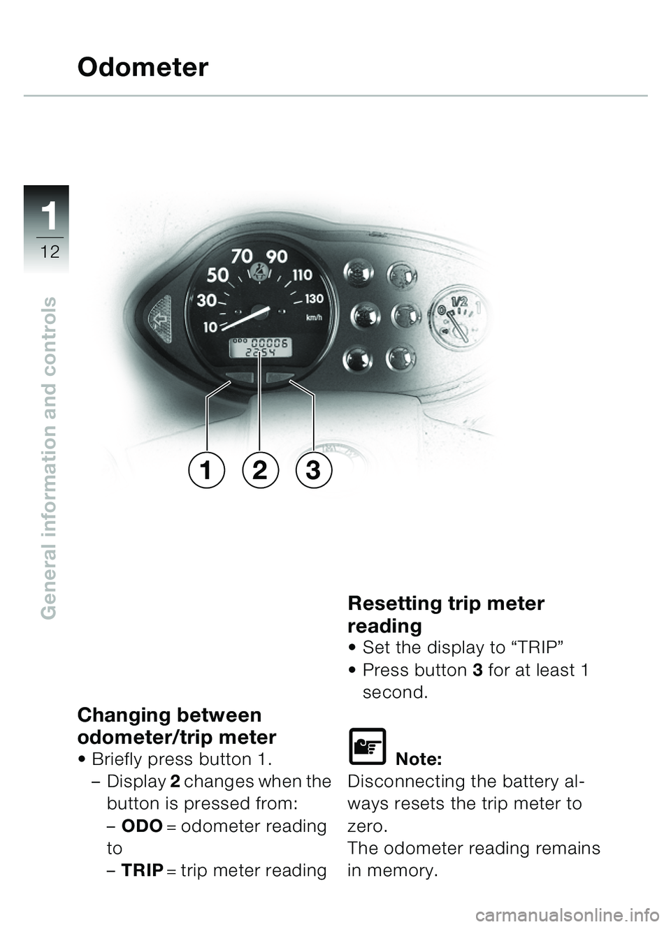
Changing between
odometer/trip meter
Briefly press button 1.
– Display 2 changes when the
button is pressed from:
– ODO = odometer reading
to
– TRIP = trip meter reading
Resetting trip meter
reading
Set the display to “TRIP ”
Press button 3 for at least 1
second.
\f Note:
Disconnecting the battery al-
ways resets the trip meter to
zero.
The odometer reading remains
in memory.
Odometer
213
�� �
Page 15 of 96
111
13
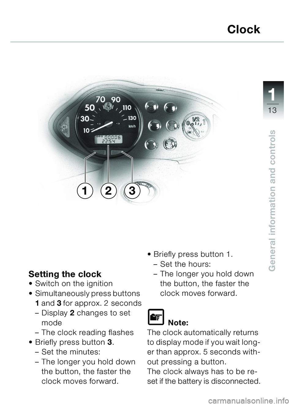
General information and controlsSetting the clockSwitch on the ignition
Simultaneously press buttons
1 and 3 for approx. 2 seconds
– Display 2 changes to set
mode
– The clock reading flashes
Briefly press button 3.
– Set the minutes:
– The longer you hold down
the button, the faster the
clock moves forward.
Briefly press button 1.
– Set the hours:
– The longer you hold down
the button, the faster the
clock moves forward.
\f Note:
The clock automatically returns
to display mode if you wait long-
er than approx. 5 seconds with-
out pressing a button.
The clock always has to be re-
set if the battery is disconnected.
Clock
231
�� �
Page 16 of 96
11
14
General information and controls
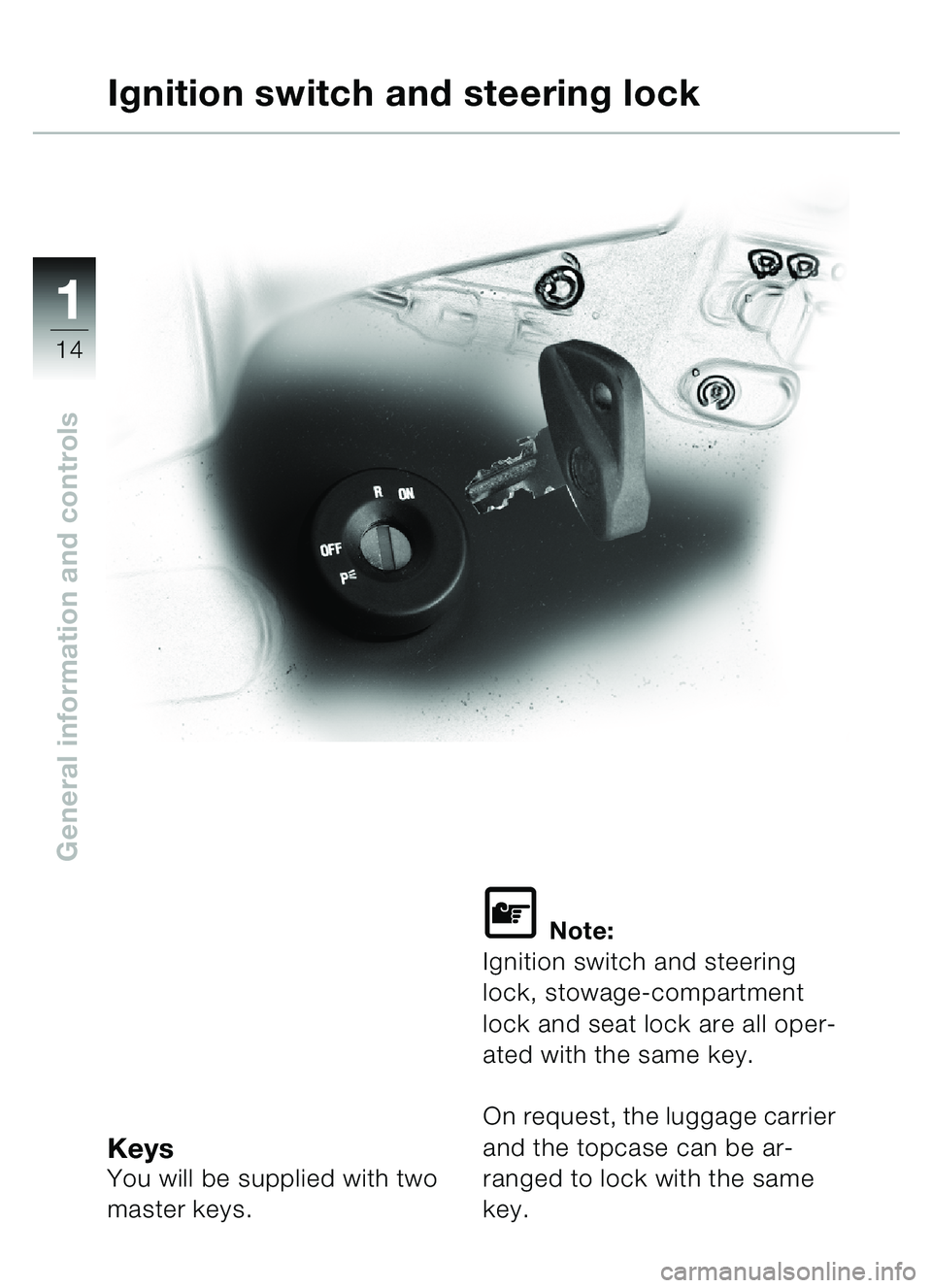
KeysYou will be supplied with two
master keys.
\f Note:
Ignition switch and steering
lock, stowage-compartment
lock and seat lock are all oper-
ated with the same key.
On request, the luggage carrier
and the topcase can be ar-
ranged to lock with the same
key.
Ignition switch and steering lock
�� �
Page 17 of 96
111
15
General information and controls
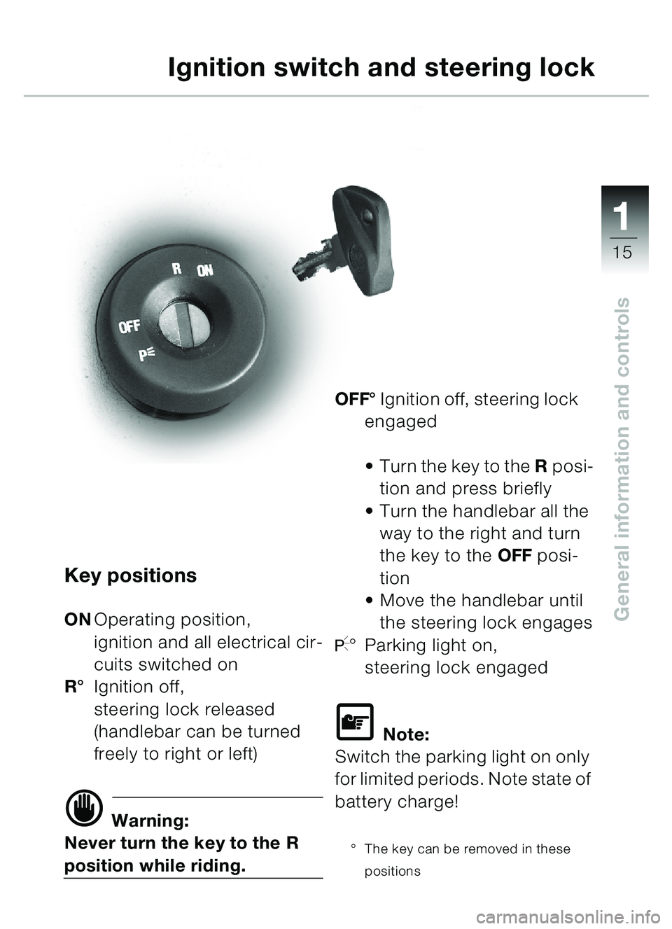
Key positions
ONOperating position,
ignition and all electrical cir-
cuits switched on
R ° Ignition off,
steering lock released
(handlebar can be turned
freely to right or left)
d Warning:
Never turn the key to the R
position while riding. OFF°
Ignition off, steering lock
engaged
Turn the key to the R posi-
tion and press briefly
Turn the handlebar all the
way to the right and turn
the key to the OFF posi-
tion
Move the handlebar until
the steering lock engages
I° Parking light on,
steering lock engaged
\f Note:
Switch the parking light on only
for limited periods. Note state of
battery charge!
° The key can be removed in these
positions
Ignition switch and steering lock
�� �
Page 18 of 96
11
16
General information and controls
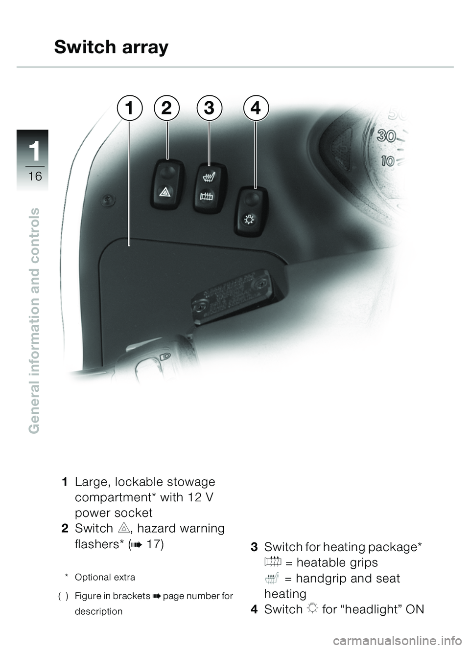
1Large, lockable stowage
compartment* with 12 V
power socket
2 Switch
C, hazard warning
flashers* (
b17)
* Optional extra
( ) Figure in brackets
bpage number for
description
3 Switch for heating package*
E = heatable grips
= handgrip and seat
heating
4 Switch
K for “headlight ” ON
Switch array
4132
�� �
Page 19 of 96
111
17
General information and controls
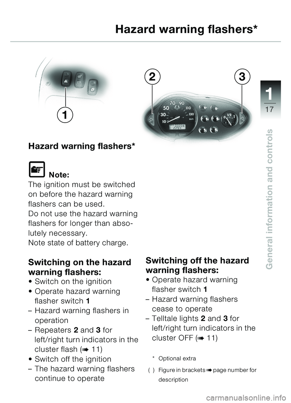
Hazard warning flashers*
\f Note:
The ignition must be switched
on before the hazard warning
flashers can be used.
Do not use the hazard warning
flashers for longer than abso-
lutely necessary.
Note state of battery charge.
Switching on the hazard
warning flashers:
Switch on the ignition
Operate hazard warning
flasher switch 1
– Hazard warning flashers in
operation
– Repeaters 2 and 3 for
left/right turn indicators in the
cluster flash (
b11)
Switch off the ignition
– The hazard warning flashers
continue to operate
Switching off the hazard
warning flashers:
Operate hazard warning
flasher switch 1
– Hazard warning flashers
cease to operate
– Telltale lights 2 and 3 for
left/right turn indicators in the
cluster OFF (
b11)
* Optional extra
( ) Figure in brackets
bpage number for
description
Hazard warning flashers*
32
1
�� �
Page 20 of 96
11
18
General information and controlsd Warning:
To prevent air from entering
the brake circuit:
• Do not turn the fitting on the
handlebar.
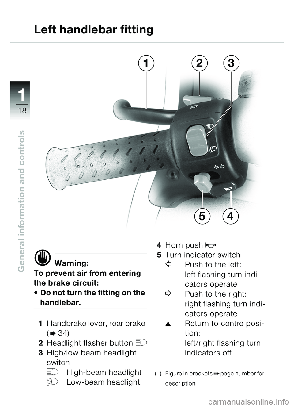
1 Handbrake lever, rear brake
(
b34)
2 Headlight flasher button
H
3High/low beam headlight
switch
FHigh-beam headlight
GLow-beam headlight 4
Horn push
z
5Turn indicator switch
YPush to the left:
left flashing turn indi-
cators operate
\bPush to the right:
right flashing turn indi-
cators operate
�Return to centre posi-
tion:
left/right flashing turn
indicators off
( ) Figure in bracketsbpage number for
description
Left handlebar fitting
3
4
21
5
�� �
Trending: service, oil temperature, alarm, ECU, odometer, fuel pressure, clock reset
