warning BMW MOTORRAD K 1200 RS 2004 Rider's Manual (in English)
[x] Cancel search | Manufacturer: BMW MOTORRAD, Model Year: 2004, Model line: K 1200 RS, Model: BMW MOTORRAD K 1200 RS 2004Pages: 80, PDF Size: 5.57 MB
Page 2 of 80
Please note
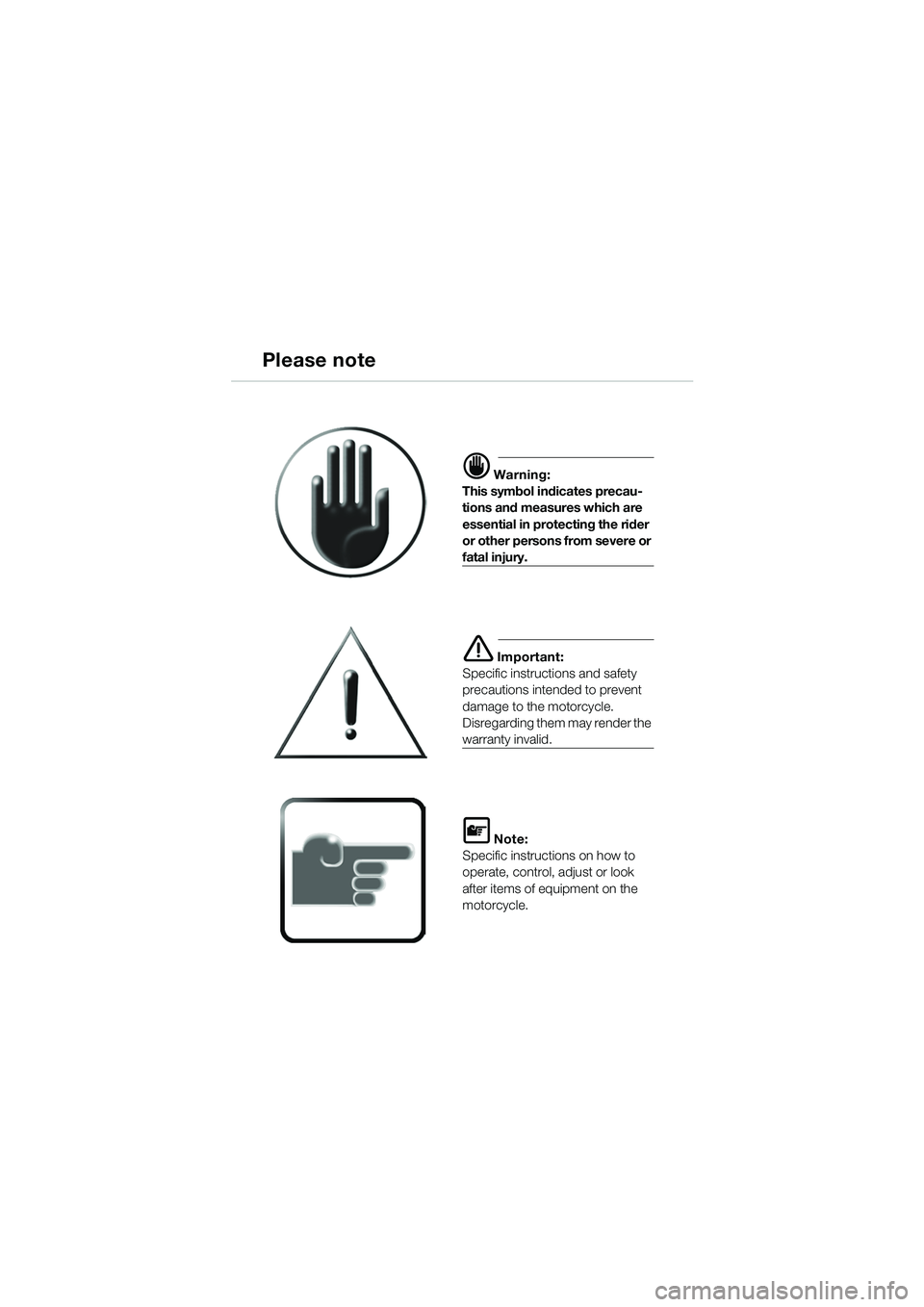
d Warning:
This symbol indicates precau-
tions and measures which are
essential in protecting the rider
or other persons from severe or
fatal injury.
e Important:
Specific instructions and safety
precautions intended to prevent
damage to the motorcycle.
Disregarding them may render the
warranty invalid.
L Note:
Specific instructions on how to
operate, control, adjust or look
after items of equipment on the
motorcycle.
20k41bkg3.book Seite 82 Mittwoch, 26. Mai 2004 3:33 15
Page 17 of 80
15
Maintenance and care
2
Your motorcycle is equipped
with Digital Motor Electronic
(MOTRONIC) engine manage-
ment and a high-output ignition
system.
d Warning:
When the engine is running or
the ignition is switched on, do
not touch electrically live
components, terminals or
wiring.
–Risk of fatal accident!
Work on the electrical system
only when the circuit has
been interrupted (switch off
ignition). For greater safety,
disconnect and insulate the
negative battery lead. If you intend to perform the
maintenance and general care
work described in the following
section yourself, you must pos-
sess the necessary knowledge
of technical matters and
mechanical skills.
Your motorcycle is built to high
technological standards. Spe-
cial tools and purpose-
designed diagnosis and testing
equipment, together with the
appropriate knowledge, are
needed to keep your motorcy-
cle in optimum working order.
General instructions
20k41bkg3.book Seite 15 Mittwoch, 26. Mai 2004 3:33 15
Page 19 of 80
17
Maintenance and care
2
General instructions
Technical modifications
d Warning:
The data stored in the
MOTRONIC control unit is the
result of extensive experi-
mental and testing work.
Tampering with the
MOTRONIC control unit rep-
resents an increased safety
risk for the rider.
L Note:
Tampering with the MOTRONIC
control unit invalidates the war-
ranty.
20k41bkg3.book Seite 17 Mittwoch, 26. Mai 2004 3:33 15
Page 23 of 80
21
Maintenance and care
2
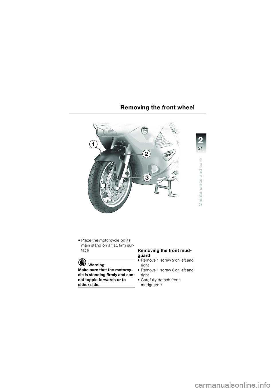
Place the motorcycle on its main stand on a flat, firm sur-
face
d Warning:
Make sure that the motorcy-
cle is standing firmly and can-
not topple forwards or to
either side.
Removing the front mud-
guard
Remove 1 screw 2 on left and
right
Remove 1 screw 3 on left and
right
Carefully detach front
mudguard 1
Removing the front wheel
2
3
1
20k41bkg3.book Seite 21 Mittwoch, 26. Mai 2004 3:33 15
Page 25 of 80
23
Maintenance and care
2
Removing the front wheel
d Warning:
Make sure that the motorcy-
cle is standing firmly and can-
not tip forward or to either
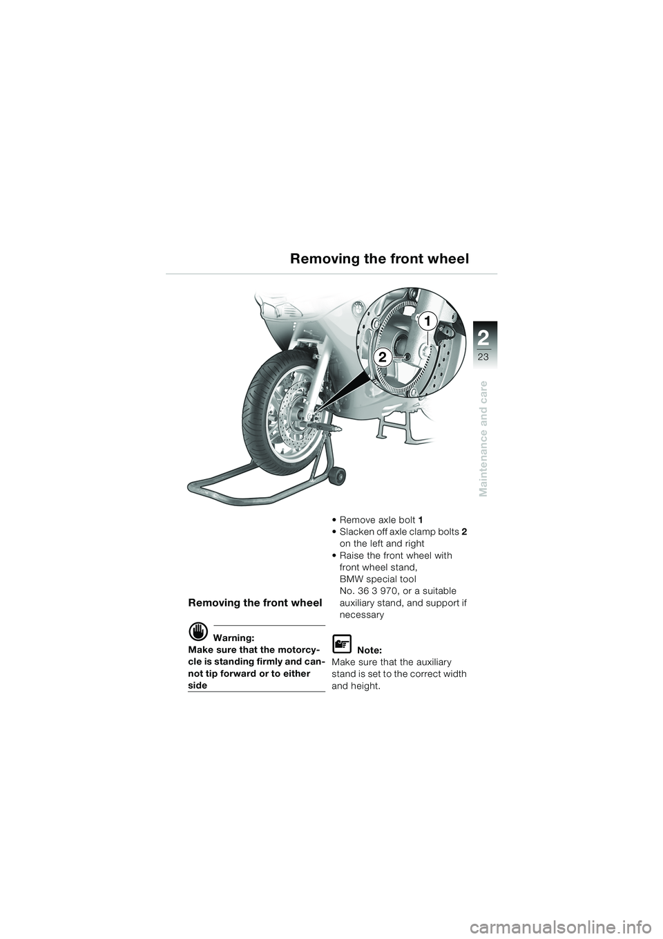
side Remove axle bolt
1
Slacken off axle clamp bolts 2
on the left and right
Raise the front wheel with front wheel stand,
BMW special tool
No. 36 3 970, or a suitable
auxiliary stand, and support if
necessary
L Note:
Make sure that the auxiliary
stand is set to the correct width
and height.
Removing the front wheel
1
2
20k41bkg3.book Seite 23 Mittwoch, 26. Mai 2004 3:33 15
Page 28 of 80
26
Maintenance and care
2
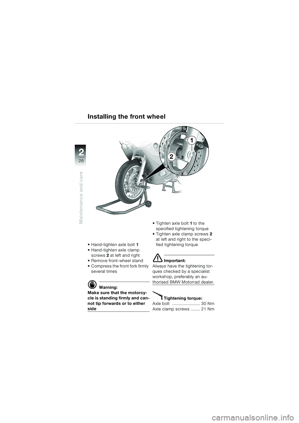
Hand-tighten axle bolt1
Hand-tighten axle clamp screws 2 at left and right
Remove front-wheel stand
Compress the front fork firmly several times
d Warning:
Make sure that the motorcy-
cle is standing firmly and can-
not tip forwards or to either
side Tighten axle bolt
1 to the
specified tightening torque
Tighten axle clamp screws 2
at left and right to the speci-
fied tightening torque
e Important:
Always have the tightening tor-
ques checked by a specialist
workshop, preferably an au-
thorised BMW Motorrad dealer.
X Tightening torque:
Axle bolt ...................... 30 Nm
Axle clamp screws ....... 21 Nm
Installing the front wheel
1
2
20k41bkg3.book Seite 26 Mittwoch, 26. Mai 2004 3:33 15
Page 30 of 80
28
Maintenance and care
2
Installing the front wheel
Installing the front mud-
guard
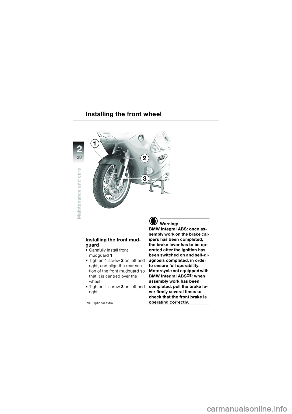
Carefully install front mudguard 1
Tighten 1 screw 2 on left and
right, and align the rear sec-
tion of the front mudguard so
that it is centred over the
wheel
Tighten 1 screw 3 on left and
right
OEOptional extra
d Warning:
BMW Integral ABS: once as-
sembly work on the brake cal-
ipers has been completed,
the brake lever has to be op-
erated after the ignition has
been switched on and self-di-
agnosis completed, in order
to ensure full operability.
Motorcycle not equipped with
BMW Integral ABS
OE: when
assembly work has been
completed, pull the brake le-
ver firmly several times to
check that the front brake is
operating correctly.
1
2
3
20k41bkg3.book Seite 28 Mittwoch, 26. Mai 2004 3:33 15
Page 35 of 80
33
Maintenance and care
2
d Warning:
Motorcycle not equipped with
BMW Integral ABS
OE: when
assembly work has been
completed, depress the brake
pedal firmly several times to
check that the rear brake is
operating correctly.
BMW Integral ABS: once as-
sembly work on the brake cal-
ipers has been completed,
the brake lever has to be op-
erated after the ignition has
been switched on and self-di-
agnosis completed, in order
to ensure full operability.
e Important:
Always have the security of the
fasteners checked by a special-
ist workshop, preferably an au-
thorised BMW Motorrad dealer.
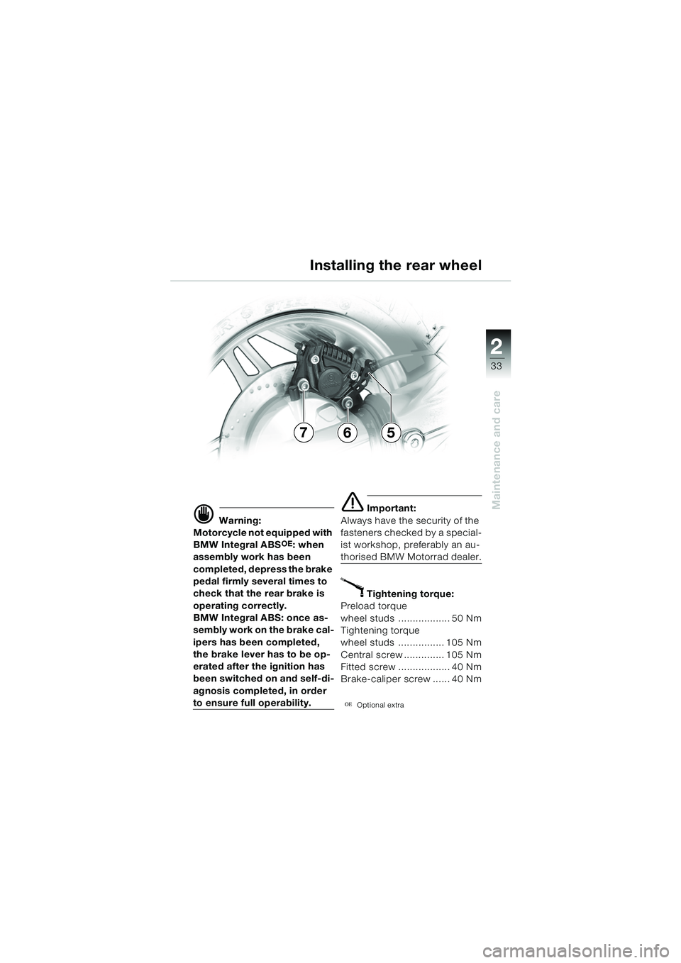
X Tightening torque:
Preload torque
wheel studs .................. 50 Nm
Tightening torque
wheel studs ................ 105 Nm
Central screw .............. 105 Nm
Fitted screw .................. 40 Nm
Brake-caliper screw ...... 40 Nm
OEOptional extra
Installing the rear wheel
576
20k41bkg3.book Seite 33 Mittwoch, 26. Mai 2004 3:33 15
Page 39 of 80
37
Maintenance and care
2
Information on changing bulbs
Your motorcycle is equipped
with Digital Motor Electronic
(MOTRONIC) engine manage-
ment and a high-output ignition
system.
d Warning:
Only carry out work on the
electrical system when the
circuit has been interrupted
(switch off ignition). For
greater safety, disconnect
and insulate the negative bat-
tery lead.
When the engine is running or
the ignition is switched on, do
not touch any electrically live
components, terminals or
wiring.
–Risk of fatal accident!
e Important:
Your vehicle has a high-beam/
low-beam bulb, a brake-light
bulb/rear-light bulb, a parking-
light bulb, a bulb for the
number-plate light, and four
bulbs for the turn indicators.
If any of these bulbs fail, you
may have problems in seeing
and being seen.
You should therefore always
carry spare bulbs on the motor-
cycle.
L Note:
Do not touch the glass of new
bulbs with the fingers.
Use a clean, dry cloth to hold
the bulbs when inserting them.
Dirt deposits, in particular oil
and grease, interfere with heat
radiation from the bulb. This
leads to overheating and short-
ens the bulb’s operating life.
20k41bkg3.book Seite 37 Mittwoch, 26. Mai 2004 3:33 15
Page 51 of 80
49
Maintenance and care
2
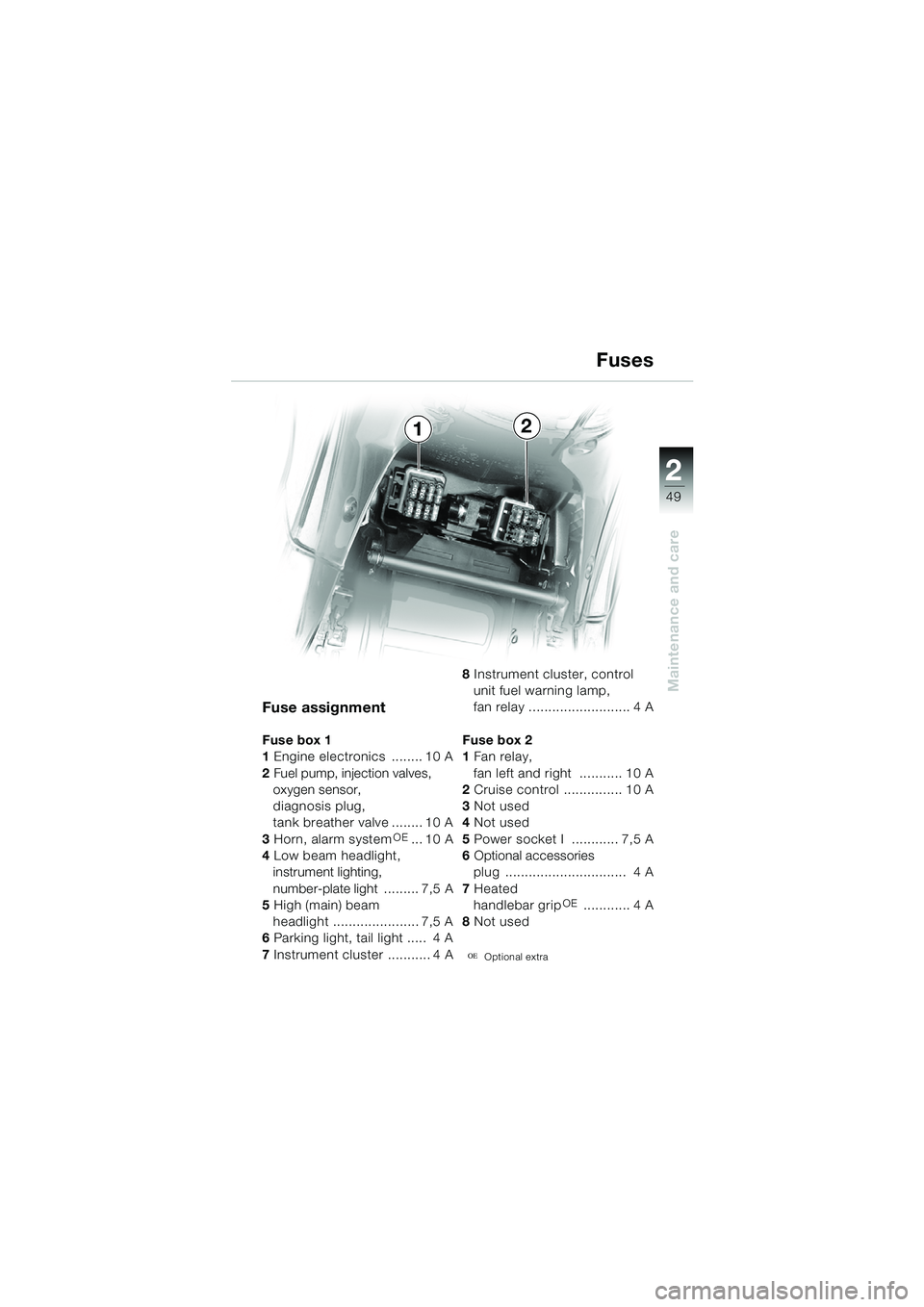
Fuse assignment
Fuse box 1
1 Engine electronics ........ 10 A
2 Fuel pump, injection valves,
oxygen sensor,
diagnosis plug,
tank breather valve ........ 10 A
3 Horn, alarm system
OE... 10 A
4 Low beam headlight,
instrument lighting,
number-plate light ......... 7,5 A
5 High (main) beam
headlight ...................... 7,5 A
6 Parking light, tail light ..... 4 A
7 Instrument cluster ........... 4 A 8
Instrument cluster, control
unit fuel warning lamp,
fan relay .......................... 4 A
Fuse box 2
1 Fan relay,
fan left and right ........... 10 A
2 Cruise control ............... 10 A
3 Not used
4 Not used
5 Power socket I ............ 7,5 A
6 Optional accessories
plug ............................... 4 A
7 Heated
handlebar grip
OE ............ 4 A
8 Not used
OEOptional extra
Fuses
12
20k41bkg3.book Seite 49 Mittwoch, 26. Mai 2004 3:33 15