BMW X5 2004 E53 Owner's Guide
Manufacturer: BMW, Model Year: 2004, Model line: X5, Model: BMW X5 2004 E53Pages: 52, PDF Size: 3.07 MB
Page 31 of 52
31
Front Suspension
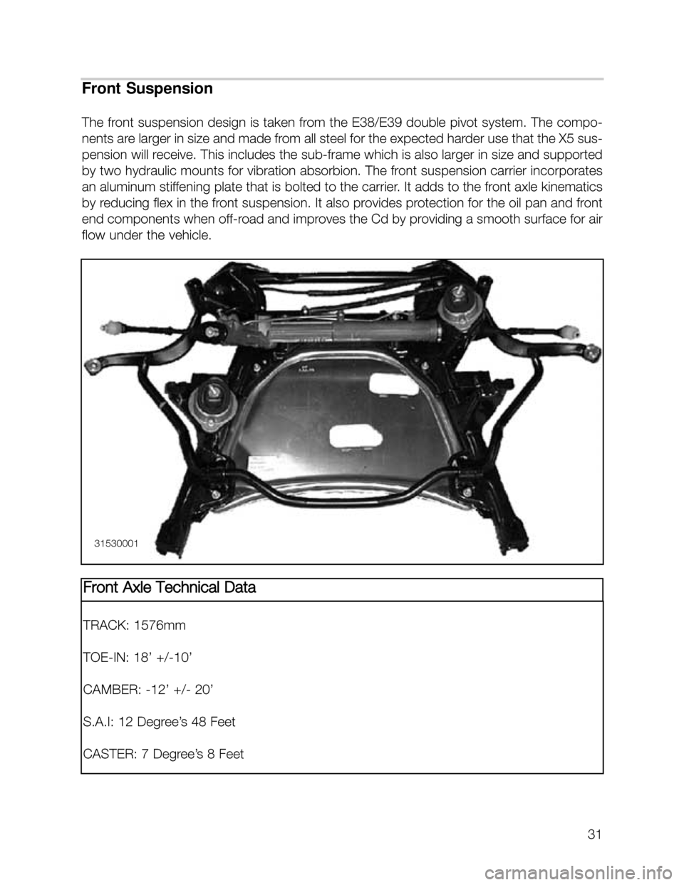
The front suspension design is taken from the E38/E39 double pivot system. The compo-
nents are larger in size and made from all steel for the expected harder use that the X5 sus-
pension will receive. This includes the sub-frame which is also larger in size and supported
by two hydraulic mounts for vibration absorbion. The front suspension carrier incorporates
an aluminum stiffening plate that is bolted to the carrier. It adds to the front axle kinematics
by reducing flex in the front suspension. It also provides protection for the oil pan and front
end components when off-road and improves the Cd by providing a smooth surface for air
flow under the vehicle.
31530001
Front Axle Technical Data
TRACK: 1576mm
TOE-IN: 18’ +/-10’
CAMBER: -12’ +/- 20’
S.A.I: 12 Degree’s 48 Feet
CASTER: 7 Degree’s 8 Feet
Page 32 of 52
32
Front Suspension Alignment
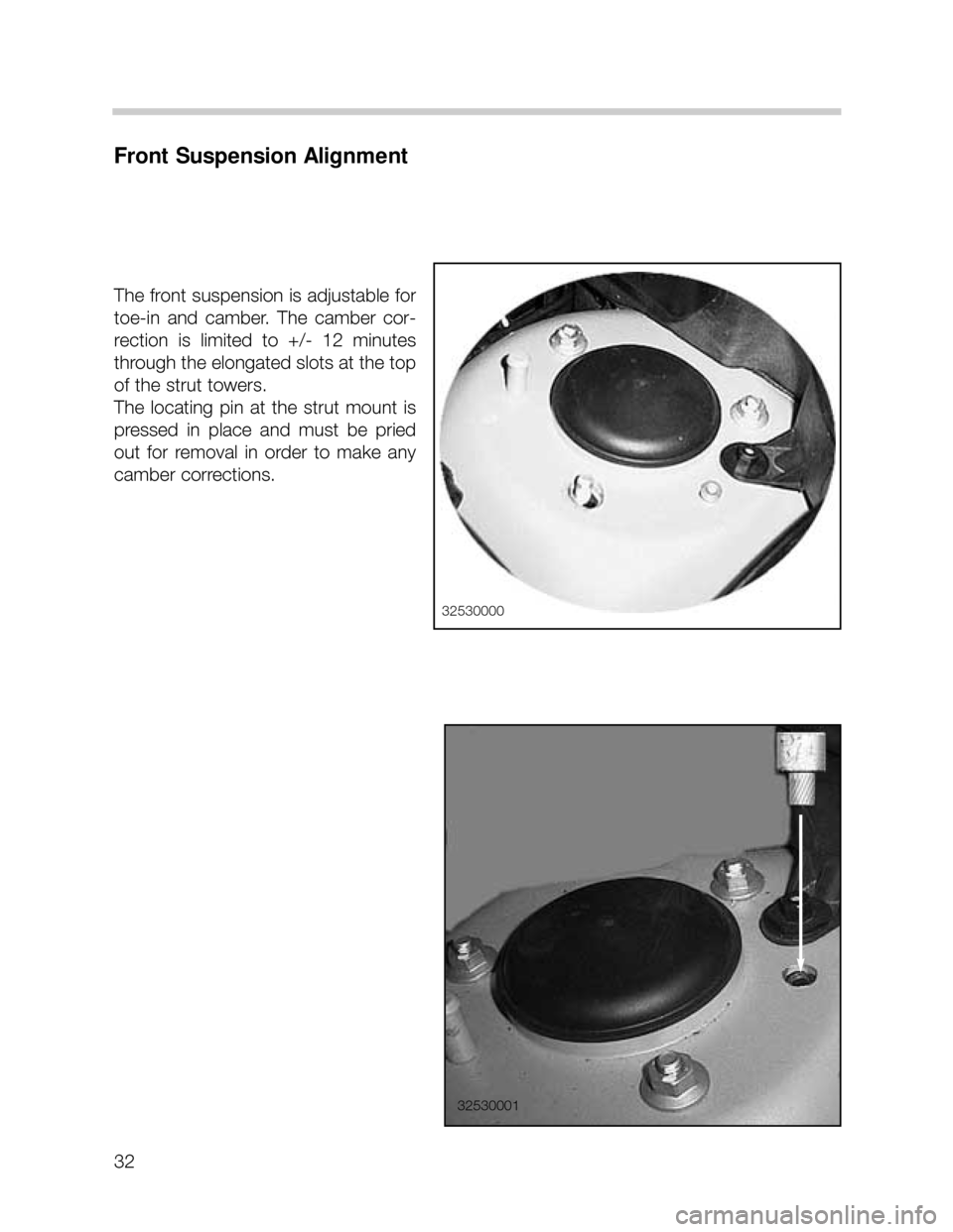
The front suspension is adjustable for
toe-in and camber. The camber cor-
rection is limited to +/- 12 minutes
through the elongated slots at the top
of the strut towers.
The locating pin at the strut mount is
pressed in place and must be pried
out for removal in order to make any
camber corrections.
32530000
32530001
Page 33 of 52
33
Rear Suspension
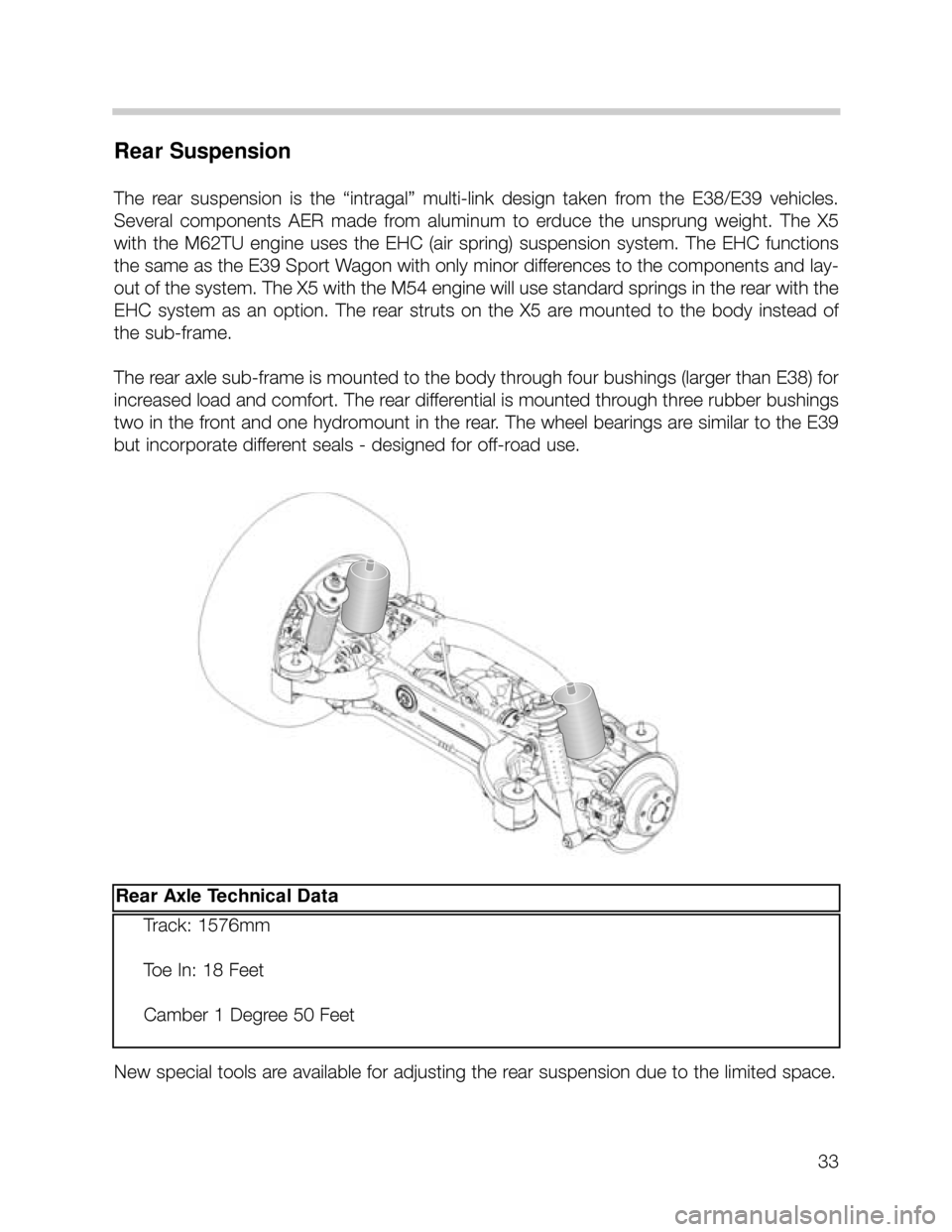
The rear suspension is the “intragal” multi-link design taken from the E38/E39 vehicles.
Several components AER made from aluminum to erduce the unsprung weight. The X5
with the M62TU engine uses the EHC (air spring) suspension system. The EHC functions
the same as the E39 Sport Wagon with only minor differences to the components and lay-
out of the system. The X5 with the M54 engine will use standard springs in the rear with the
EHC system as an option. The rear struts on the X5 are mounted to the body instead of
the sub-frame.
The rear axle sub-frame is mounted to the body through four bushings (larger than E38) for
increased load and comfort. The rear differential is mounted through three rubber bushings
two in the front and one hydromount in the rear. The wheel bearings are similar to the E39
but incorporate different seals - designed for off-road use.
New special tools are available for adjusting the rear suspension due to the limited space.
Rear Axle Technical Data
Track: 1576mm
Toe In: 18 Feet
Camber 1 Degree 50 Feet
Page 34 of 52
34
Rear Suspension Alignment
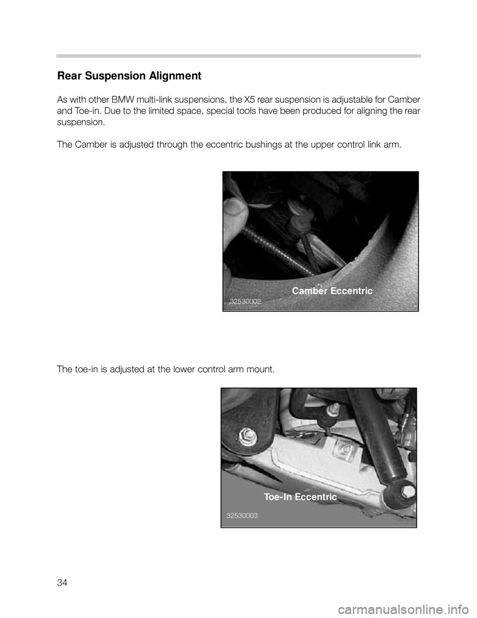
As with other BMW multi-link suspensions, the X5 rear suspension is adjustable for Camber
and Toe-in. Due to the limited space, special tools have been produced for aligning the rear
suspension.
The Camber is adjusted through the eccentric bushings at the upper control link arm.
The toe-in is adjusted at the lower control arm mount.
Camber Eccentric
Toe-In Eccentric
3253000332530002
Page 35 of 52
35
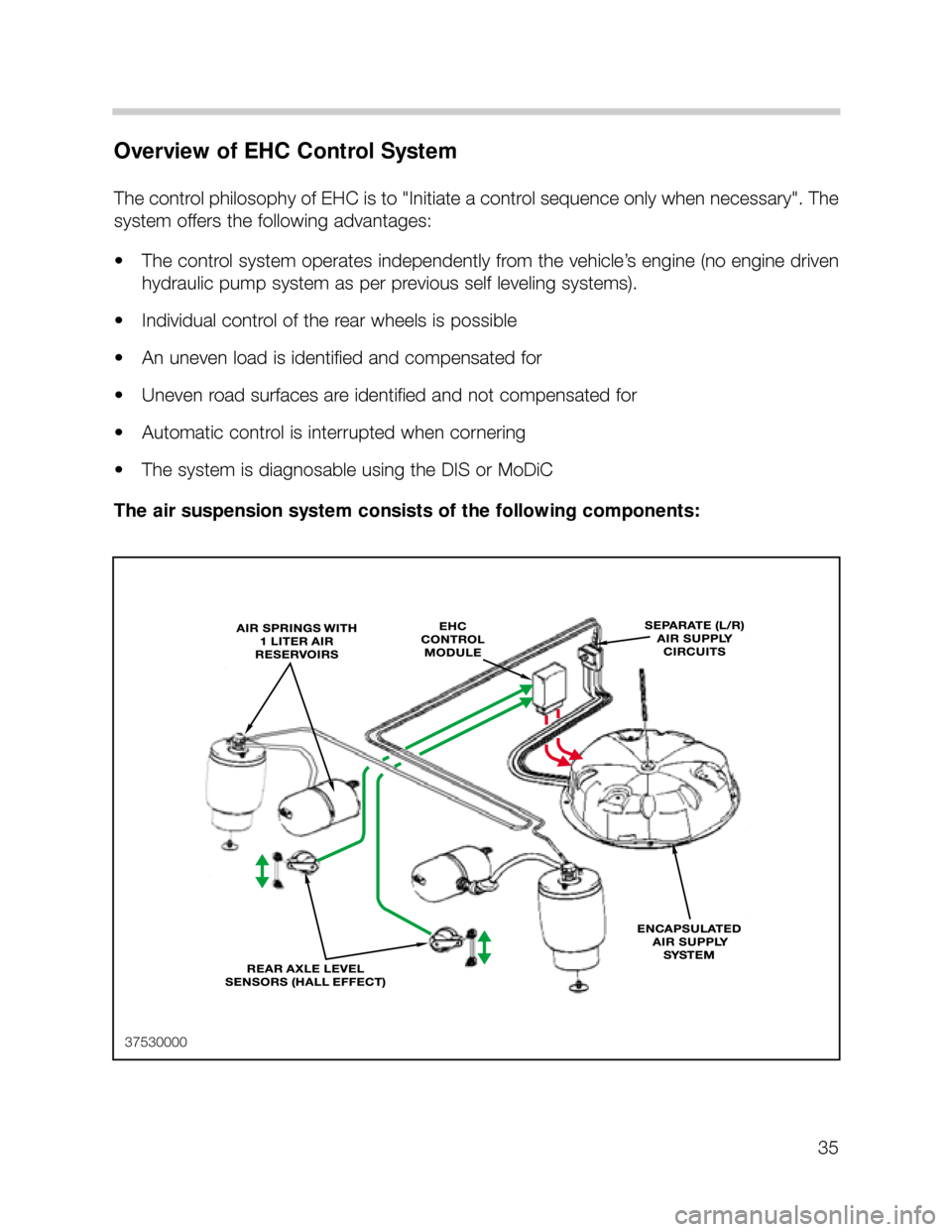
Overview of EHC Control System
The control philosophy of EHC is to "Initiate a control sequence only when necessary". The
system offers the following advantages:
• The control system operates independently from the vehicle’s engine (no engine driven
hydraulic pump system as per previous self leveling systems).
• Individual control of the rear wheels is possible
• An uneven load is identified and compensated for
• Uneven road surfaces are identified and not compensated for
• Automatic control is interrupted when cornering
• The system is diagnosable using the DIS or MoDiC
The air suspension system consists of the following components:
37530000
Page 36 of 52
36
EHC System Components
Control Module
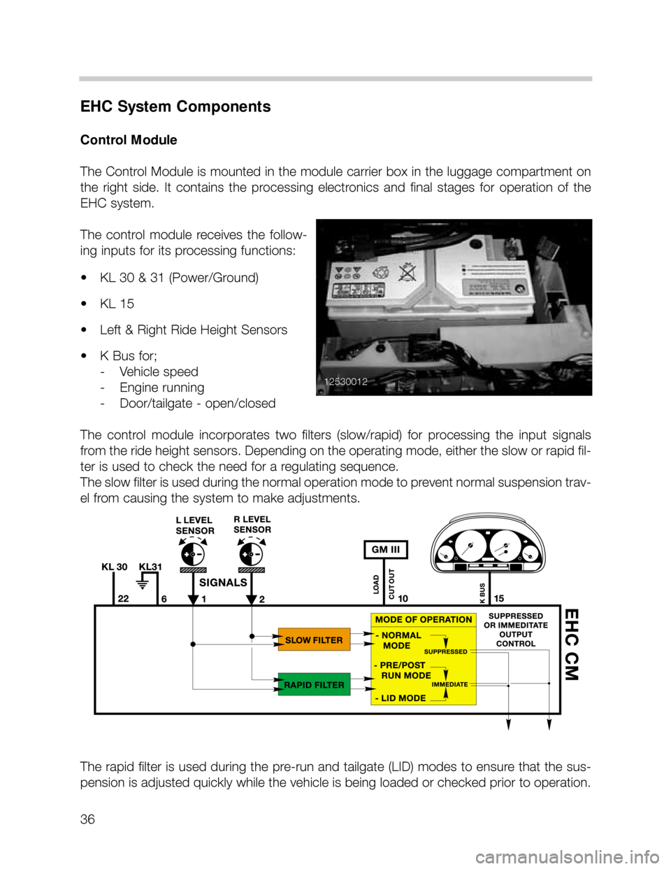
The Control Module is mounted in the module carrier box in the luggage compartment on
the right side. It contains the processing electronics and final stages for operation of the
EHC system.
The control module receives the follow-
ing inputs for its processing functions:
• KL 30 & 31 (Power/Ground)
• KL 15
• Left & Right Ride Height Sensors
• K Bus for;
- Vehicle speed
- Engine running
- Door/tailgate - open/closed
The control module incorporates two filters (slow/rapid) for processing the input signals
from the ride height sensors. Depending on the operating mode, either the slow or rapid fil-
ter is used to check the need for a regulating sequence.
The slow filter is used during the normal operation mode to prevent normal suspension trav-
el from causing the system to make adjustments.
The rapid filter is used during the pre-run and tailgate (LID) modes to ensure that the sus-
pension is adjusted quickly while the vehicle is being loaded or checked prior to operation.
12530012
Page 37 of 52
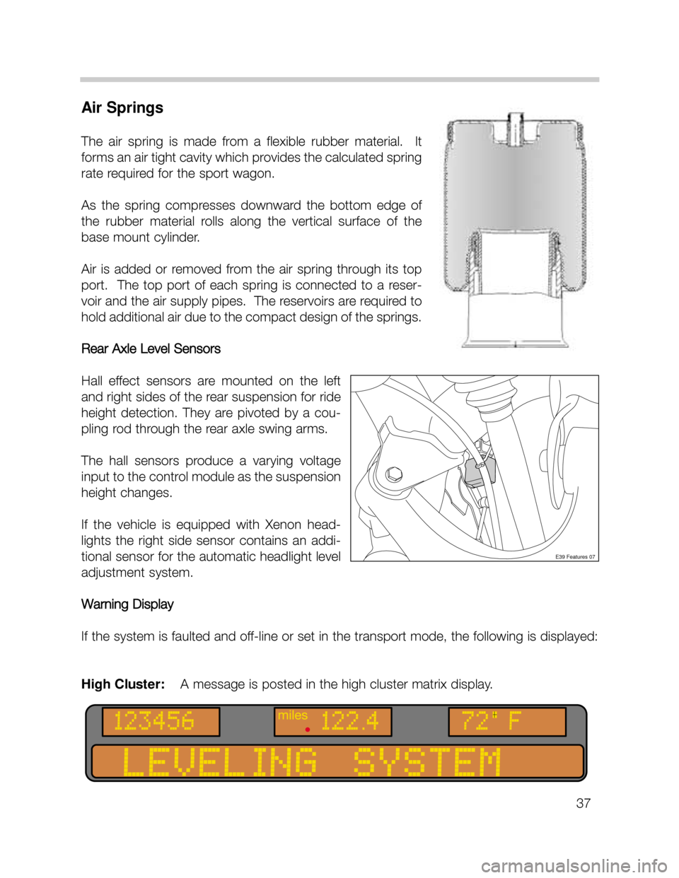
Air Springs
The air spring is made from a flexible rubber material. It
forms an air tight cavity which provides the calculated spring
rate required for the sport wagon.
As the spring compresses downward the bottom edge of
the rubber material rolls along the vertical surface of the
base mount cylinder.
Air is added or removed from the air spring through its top
port. The top port of each spring is connected to a reser-
voir and the air supply pipes. The reservoirs are required to
hold additional air due to the compact design of the springs.
Rear Axle Level Sensors
Hall effect sensors are mounted on the left
and right sides of the rear suspension for ride
height detection. They are pivoted by a cou-
pling rod through the rear axle swing arms.
The hall sensors produce a varying voltage
input to the control module as the suspension
height changes.
If the vehicle is equipped with Xenon head-
lights the right side sensor contains an addi-
tional sensor for the automatic headlight level
adjustment system.
Warning Display
If the system is faulted and off-line or set in the transport mode, the following is displayed:
High Cluster: A message is posted in the high cluster matrix display.
E39 Features 07
37
Page 38 of 52
Air Supply System (LVA)
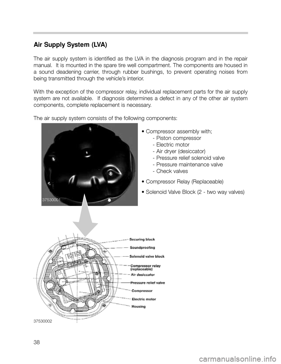
The air supply system is identified as the LVA in the diagnosis program and in the repair
manual. It is mounted in the spare tire well compartment. The components are housed in
a sound deadening carrier, through rubber bushings, to prevent operating noises from
being transmitted through the vehicle’s interior.
With the exception of the compressor relay, individual replacement parts for the air supply
system are not available. If diagnosis determines a defect in any of the other air system
components, complete replacement is necessary.
The air supply system consists of the following components:
• Compressor assembly with;
- Piston compressor
- Electric motor
- Air dryer (desiccator)
- Pressure relief solenoid valve
- Pressure maintenance valve
- Check valves
• Compressor Relay (Replaceable)
• Solenoid Valve Block (2 - two way valves)
38
3753000237530001
Page 39 of 52
Air Supply System (LVA) Operation
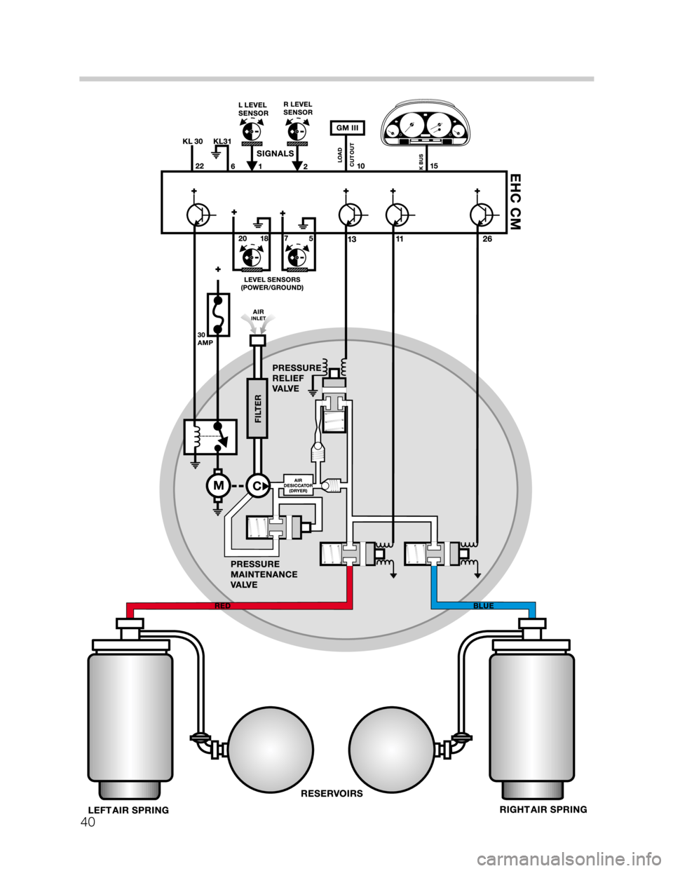
The single stage piston compressor produces a maximum pressure of 13.5 Bar. The com-
pressor is maintenance free - provided it is used in a dust free environment. This includes
the compressor’s intake air filter.
The compressor is driven by a DC motor that is controlled by the compressor relay through
the control module.
When the compressor is activated, the pressure builds up to a working pressure of 11.4
Bar (+0.8/-1.5 Bar). This is controlled through the pressure maintenance valve. The air
under pressure is fed through the dryer and check valve to the solenoid valve block for the
air springs.
There is one solenoid valve in the valve block for each air strut. This allows the system to
compensate for uneven loads in the vehicle and maintain the vehicles ride height at all
times.
Pressure is drained through the left or right solenoid valve (energized open) the pressure
relief solenoid valve, restricter, check valve and dryer back to the inlet side of the compres-
sor pump.
39
Page 40 of 52
40