BMW X5 2004 E53 Service Manual
Manufacturer: BMW, Model Year: 2004, Model line: X5, Model: BMW X5 2004 E53Pages: 52, PDF Size: 3.07 MB
Page 41 of 52
41
EHC System Operation
A fully functional EHC system is controlled by one of three different modes of operation.
The operation mode is selected by the control module based on current conditions provid-
ed by the monitored input signals. The main modes of operation are:
• Pre-Run/Post-Run Mode
Normal Mode
Tailgate Mode
Two special operating modes are also included in the control module programming.
New/replacement mode(pre ZCS encoded). This mode provides basic operation.
Transport Mode - Transport mode is set at the factory and raises the vehicle 30mm to
prevent vehicle damage during transportation. It must be deactivated with the DIS/
MoDiC prior to customer delivery.
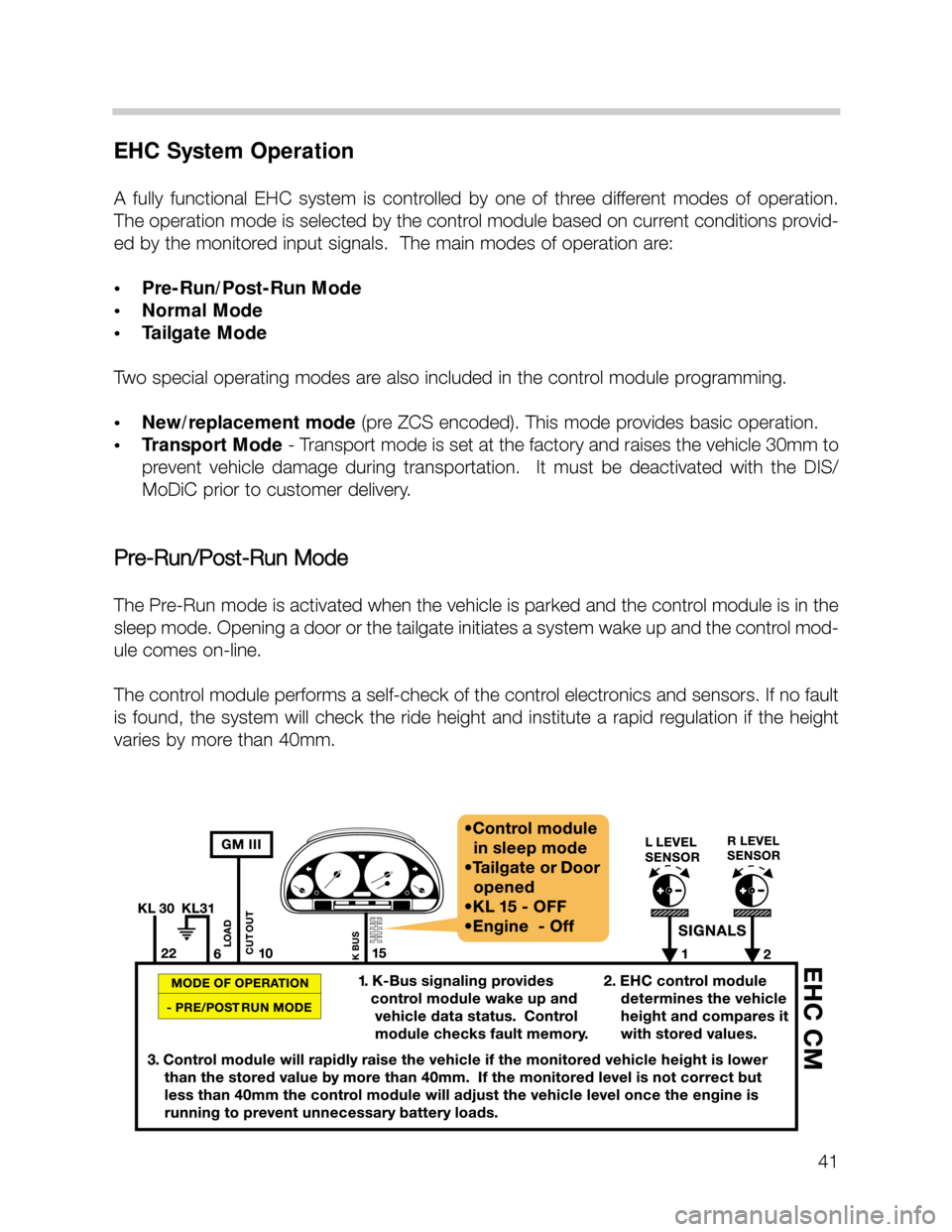
Pre-Run/Post-Run Mode
The Pre-Run mode is activated when the vehicle is parked and the control module is in the
sleep mode. Opening a door or the tailgate initiates a system wake up and the control mod-
ule comes on-line.
The control module performs a self-check of the control electronics and sensors. If no fault
is found, the system will check the ride height and institute a rapid regulation if the height
varies by more than 40mm.
Page 42 of 52
42
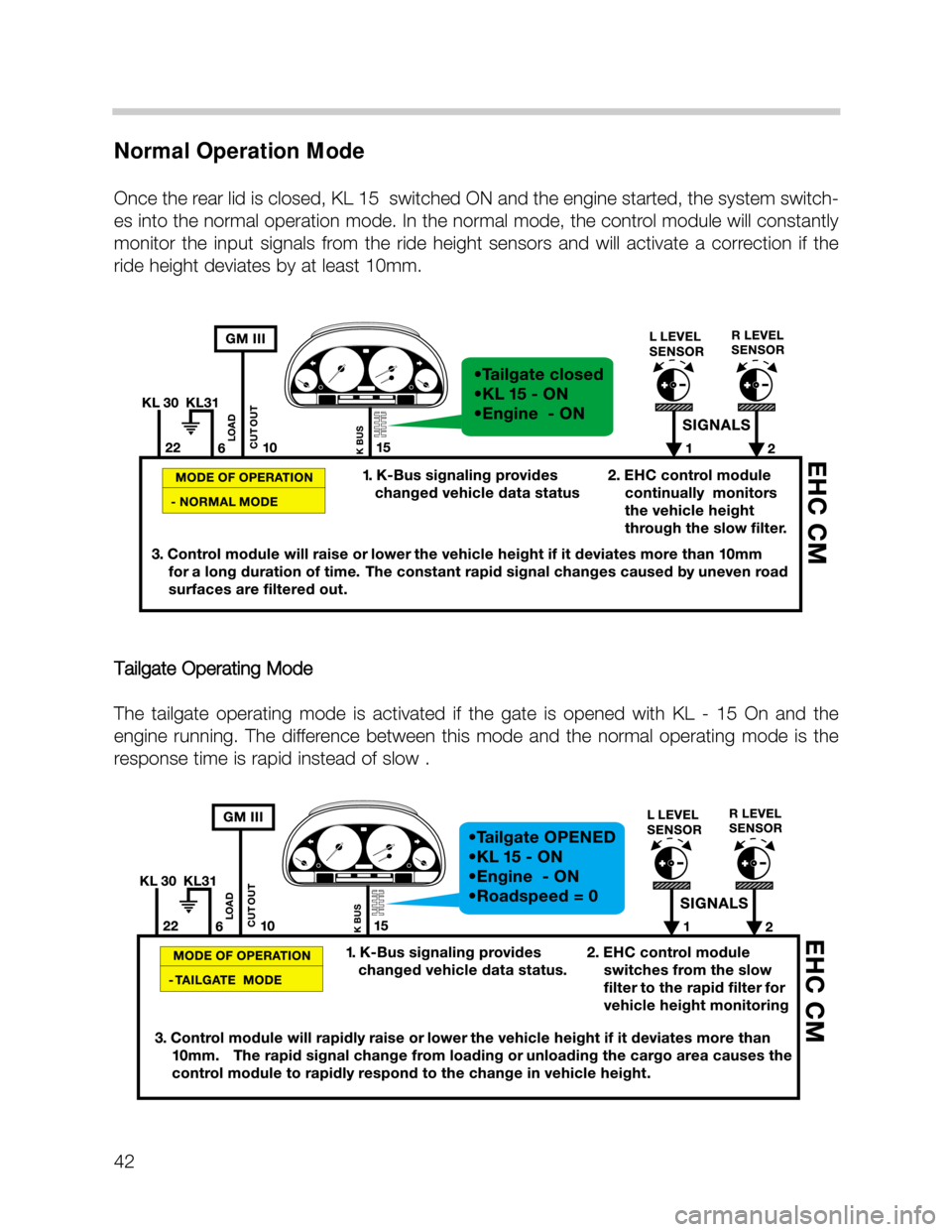
Normal Operation Mode
Once the rear lid is closed, KL 15 switched ON and the engine started, the system switch-
es into the normal operation mode. In the normal mode, the control module will constantly
monitor the input signals from the ride height sensors and will activate a correction if the
ride height deviates by at least 10mm.
Tailgate Operating Mode
The tailgate operating mode is activated if the gate is opened with KL - 15 On and the
engine running. The difference between this mode and the normal operating mode is the
response time is rapid instead of slow .
Page 43 of 52
43
Special Operation Mode
• Assembly Line Mode (New control module)
The assembly line mode refers to control module manufacturing. New control modules
are stored in a deactivated state. The control programming is not active and must first
be ZCS encoded.
After installing a replacement control module, it must be coded using the DIS or MoDiC.
The instrument cluster fault display will remain illuminated until the control module is
coded.
Control Interrupts
Cornering
To prevent unnecessary suspension adjustments while driving through corners, a “control
interrupt” is built into the system. Above 30MPH the control module monitors the left/right
ride height sensors for a difference of 30mm. Exceeding this difference will put the system
into a control interrupt and no adjustment will take place. The control interrupt last for a
duration of 5 minutes.
Vehicle Lifting
The ride height control is interrupted when the vehicle is raised on a lift or with a jack. The
system monitors the ride height sensor inputs and when the height limit of 90 mm is
exceeded, the control is switched OFF until the vehicle is lowered again.
Page 44 of 52
44
EHC Service Information
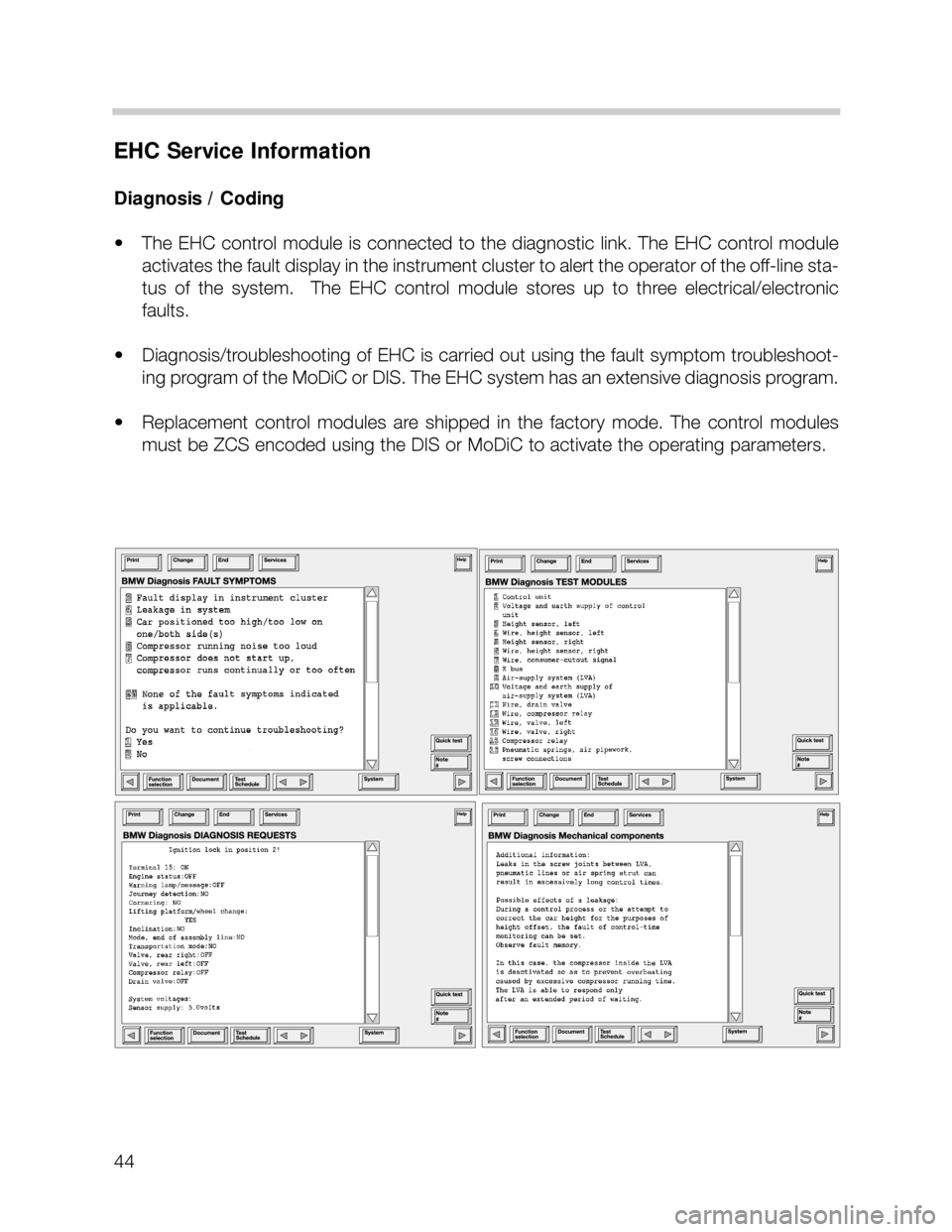
Diagnosis / Coding
• The EHC control module is connected to the diagnostic link. The EHC control module
activates the fault display in the instrument cluster to alert the operator of the off-line sta-
tus of the system. The EHC control module stores up to three electrical/electronic
faults.
• Diagnosis/troubleshooting of EHC is carried out using the fault symptom troubleshoot-
ing program of the MoDiC or DIS. The EHC system has an extensive diagnosis program.
• Replacement control modules are shipped in the factory mode. The control modules
must be ZCS encoded using the DIS or MoDiC to activate the operating parameters.
Page 45 of 52
45
DIS/Modic Service Funnction Program
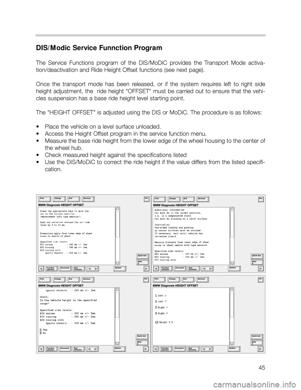
The Service Functions program of the DIS/MoDiC provides the Transport Mode activa-
tion/deactivation and Ride Height Offset functions (see next page).
Once the transport mode has been released, or if the system requires left to right side
height adjustment, the ride height "OFFSET" must be carried out to ensure that the vehi-
cles suspension has a base ride height level starting point.
The "HEIGHT OFFSET" is adjusted using the DIS or MoDiC. The procedure is as follows:
• Place the vehicle on a level surface unloaded.
• Access the Height Offset program in the service function menu.
• Measure the base ride height from the lower edge of the wheel housing to the center of
the wheel hub.
• Check measured height against the specifications listed
• Use the DIS/MoDiC to correct the ride height if the value differs from the listed specifi-
cation.
Page 46 of 52
46
Steering
The X5 utilizes a power assisted rack and pinion steering system due to all wheel drive con-
siderations. The power steering pump is a vane cell design.
The turning radius of the X5 is 12.2 meters.
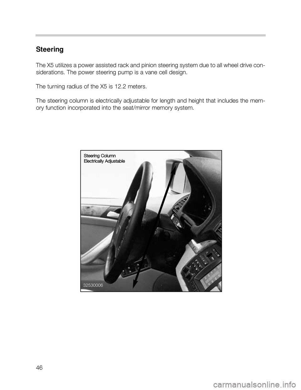
The steering column is electrically adjustable for length and height that includes the mem-
ory function incorporated into the seat/mirror memory system.
32530006
Steering Column
Electrically Adjustable
Page 47 of 52
47
Brakes
The X5 brake system is the dual circuit (black/white) division with Electronic Brake Force
distribution (EBV) through DSC control. The system is similar to the E38 with:
• Vacuum booster with tube jet amplifier
• Tandem master cylinder with two central valves for DSC operation
• Brake fluid reservoir with reed contact
• Vented front rotors/Solid rear
• Single piston calipers
• DSC hydraulic unit with integrated control
module
• Pre-load pump for DSC operation
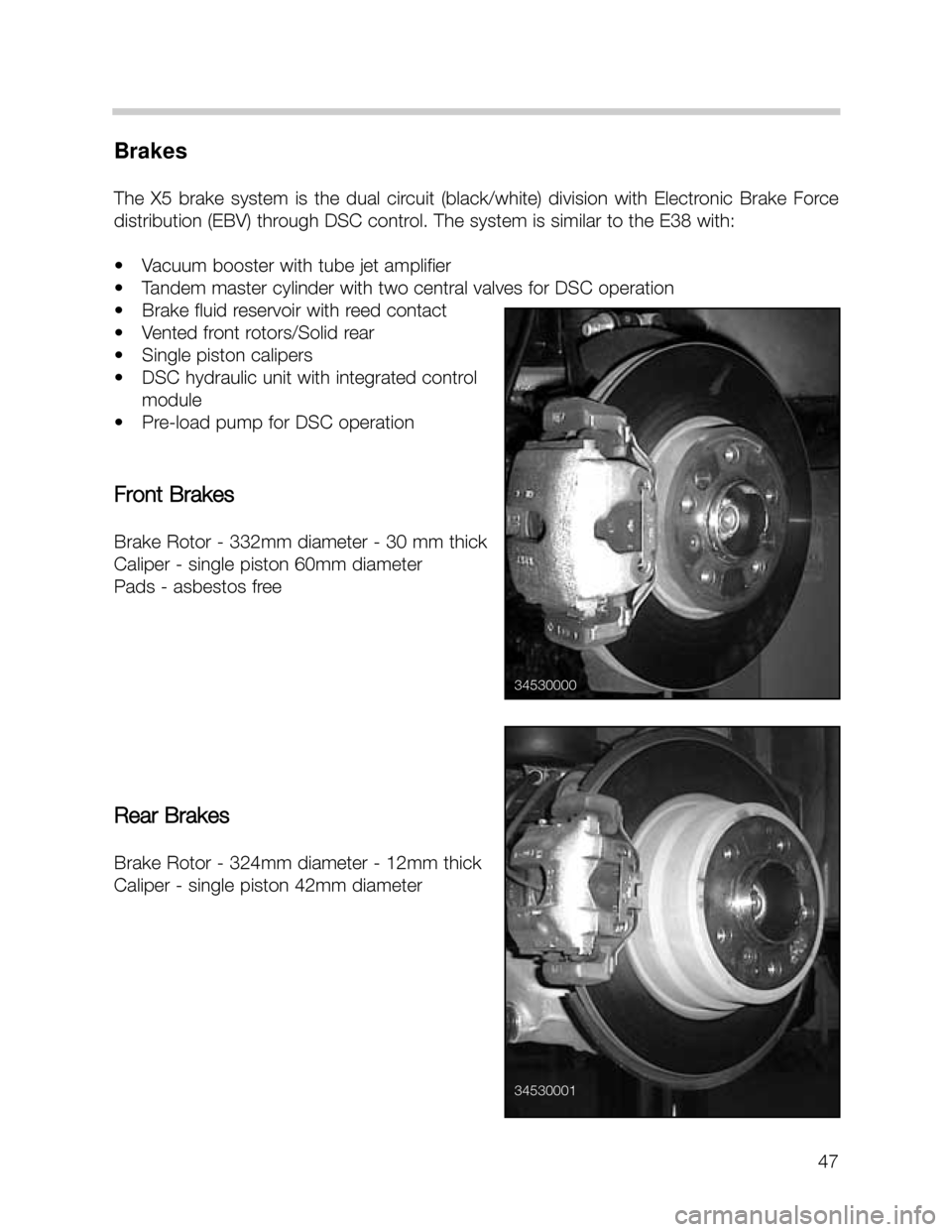
Front Brakes
Brake Rotor - 332mm diameter - 30 mm thick
Caliper - single piston 60mm diameter
Pads - asbestos free
Rear Brakes
Brake Rotor - 324mm diameter - 12mm thick
Caliper - single piston 42mm diameter
34530000
34530001
Page 48 of 52
48
Wheels and Tires
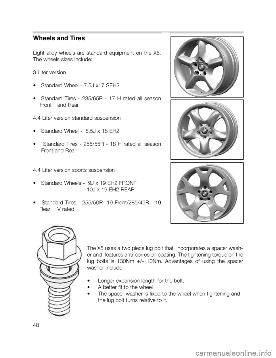
Light alloy wheels are standard equipment on the X5.
The wheels sizes include:
3 Liter version
• Standard Wheel - 7.5J x17 SEH2
• Standard Tires - 235/65R - 17 H rated all season
Front and Rear
4.4 Liter version standard suspension
• Standard Wheel - 8.5J x 18 EH2
• Standard Tires - 255/55R - 18 H rated all season
Front and Rear
4.4 Liter version sports suspension
• Standard Wheels - 9J x 19 EH2 FRONT
10J x 19 EH2 REAR
• Standard Tires - 255/50R -19 Front/285/45R - 19
Rear V rated
The X5 uses a two piece lug bolt that incorporates a spacer wash-
er and features anti-corrosion coating. The tightening torque on the
lug bolts is 130Nm +/- 10Nm. Advantages of using the spacer
washer include:
• Longer expansion length for the bolt.
• A better fit to the wheel
• The spacer washer is fixed to the wheel when tightening and
the lug bolt turns relative to it.
Page 49 of 52
49
Fuel System Supply
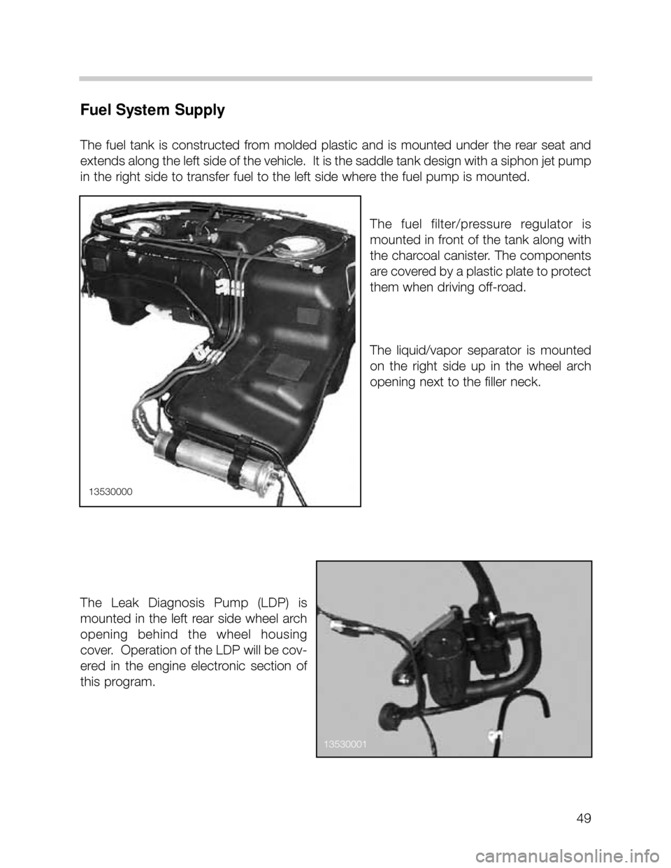
The fuel tank is constructed from molded plastic and is mounted under the rear seat and
extends along the left side of the vehicle. It is the saddle tank design with a siphon jet pump
in the right side to transfer fuel to the left side where the fuel pump is mounted.
The fuel filter/pressure regulator is
mounted in front of the tank along with
the charcoal canister. The components
are covered by a plastic plate to protect
them when driving off-road.
The liquid/vapor separator is mounted
on the right side up in the wheel arch
opening next to the filler neck.
The Leak Diagnosis Pump (LDP) is
mounted in the left rear side wheel arch
opening behind the wheel housing
cover. Operation of the LDP will be cov-
ered in the engine electronic section of
this program.
13530000
13530001
Page 50 of 52
50
Exhaust System
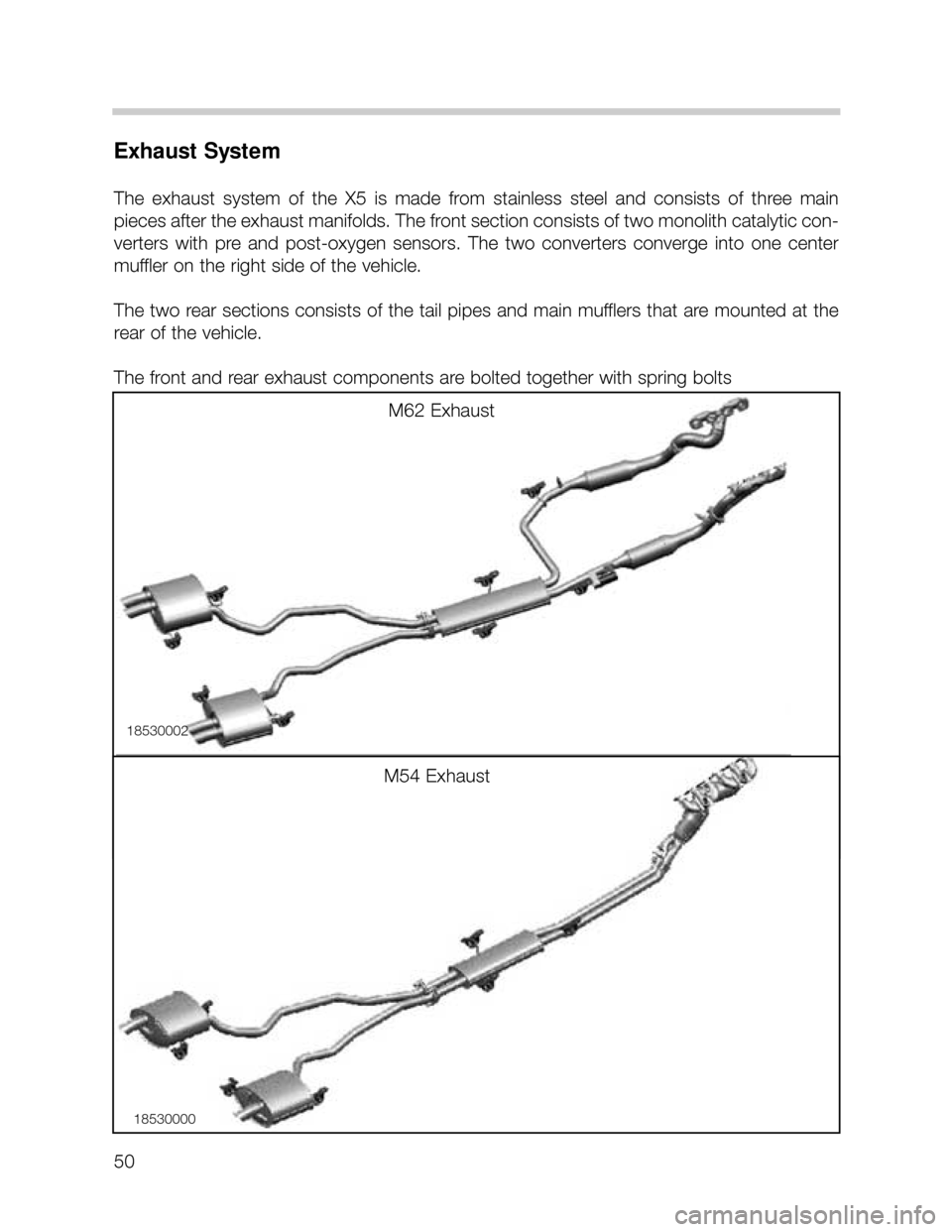
The exhaust system of the X5 is made from stainless steel and consists of three main
pieces after the exhaust manifolds. The front section consists of two monolith catalytic con-
verters with pre and post-oxygen sensors. The two converters converge into one center
muffler on the right side of the vehicle.
The two rear sections consists of the tail pipes and main mufflers that are mounted at the
rear of the vehicle.
The front and rear exhaust components are bolted together with spring bolts
M54 Exhaust
M62 Exhaust
18530002
18530000