air filter BMW X5 2005 E53 M54 Engine Workshop Manual
[x] Cancel search | Manufacturer: BMW, Model Year: 2005, Model line: X5, Model: BMW X5 2005 E53Pages: 48, PDF Size: 2.52 MB
Page 5 of 48
M54 ENGINE
MECHANICAL CHANGES
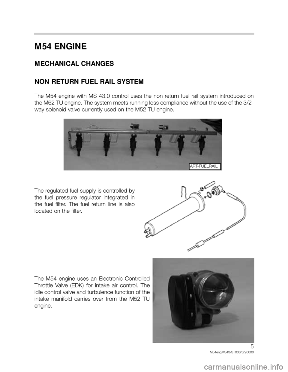
NON RETURN FUEL RAIL SYSTEM
The M54 engine with MS 43.0 control uses the non return fuel rail system introduced on
the M62 TU engine. The system meets running loss compliance without the use of the 3/2-
way solenoid valve currently used on the M52 TU engine.
The regulated fuel supply is controlled by
the fuel pressure regulator integrated in
the fuel filter. The fuel return line is also
located on the filter.
The M54 engine uses an Electronic Controlled
Throttle Valve (EDK) for intake air control. The
idle control valve and turbulence function of the
intake manifold carries over from the M52 TU
engine.
5
M54engMS43/ST036/6/20000
ART-FUELRAIL
Page 18 of 48
18
M54engms43/STO36/6/00
123
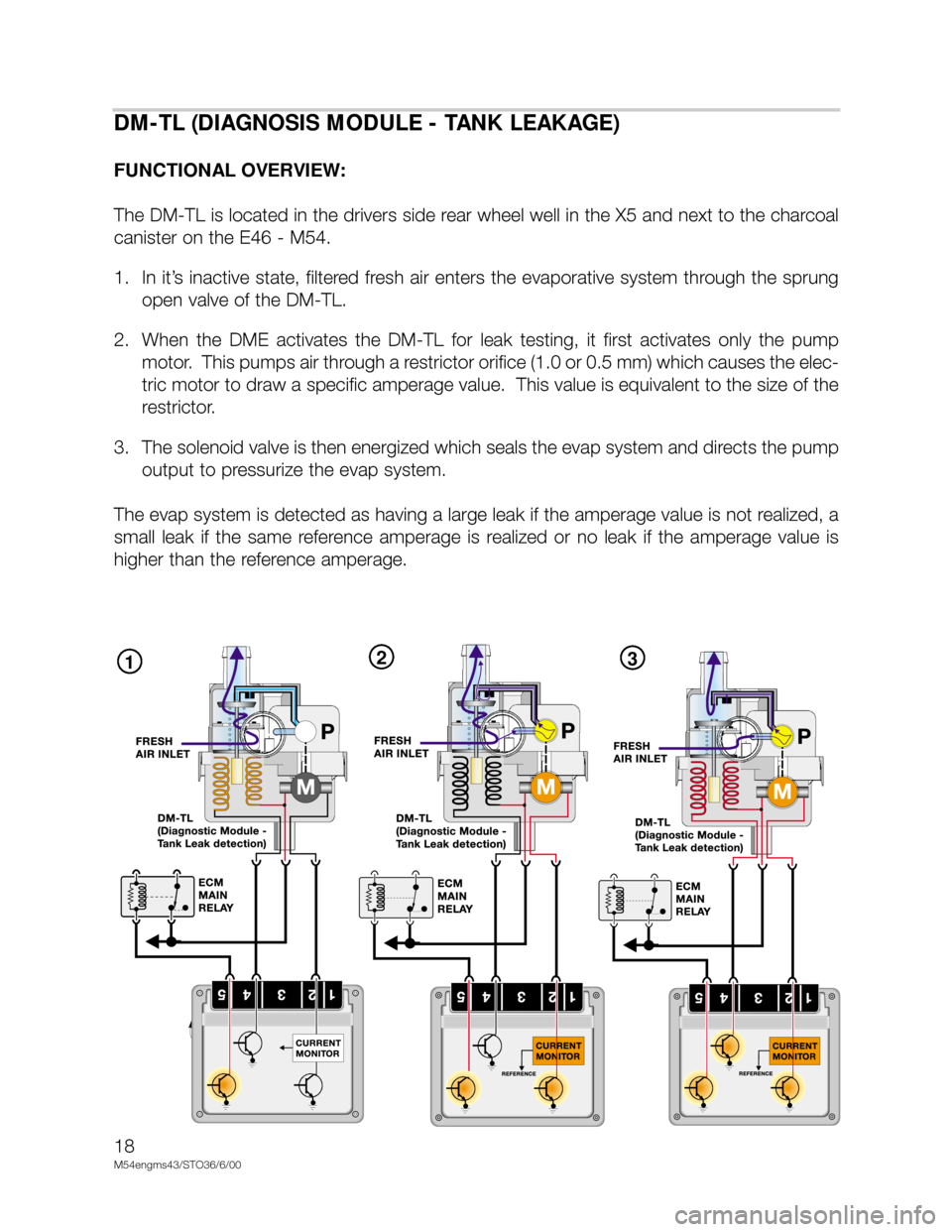
DM-TL (DIAGNOSIS MODULE - TANK LEAKAGE)
FUNCTIONAL OVERVIEW:
The DM-TL is located in the drivers side rear wheel well in the X5 and next to the charcoal
canister on the E46 - M54.
1. In it’s inactive state, filtered fresh air enters the evaporative system through the sprung
open valve of the DM-TL.
2. When the DME activates the DM-TL for leak testing, it first activates only the pump
motor. This pumps air through a restrictor orifice (1.0 or 0.5 mm) which causes the elec-
tric motor to draw a specific amperage value. This value is equivalent to the size of the
restrictor.
3. The solenoid valve is then energized which seals the evap system and directs the pump
output to pressurize the evap system.
The evap system is detected as having a large leak if the amperage value is not realized, a
small leak if the same reference amperage is realized or no leak if the amperage value is
higher than the reference amperage.
Page 21 of 48
21
M54engMS43/ST039/3/17/00
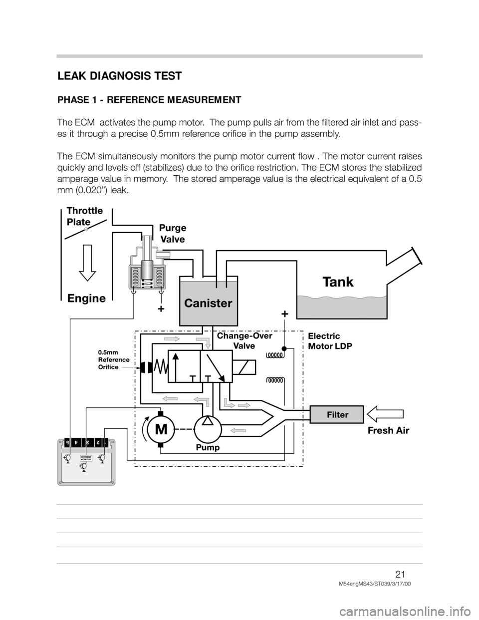
LEAK DIAGNOSIS TEST
PHASE 1 - REFERENCE MEASUREMENT
The ECM activates the pump motor. The pump pulls air from the filtered air inlet and pass-
es it through a precise 0.5mm reference orifice in the pump assembly.
The ECM simultaneously monitors the pump motor current flow . The motor current raises
quickly and levels off (stabilizes) due to the orifice restriction. The ECM stores the stabilized
amperage value in memory. The stored amperage value is the electrical equivalent of a 0.5
mm (0.020”) leak.
Page 22 of 48
22
M54engMS43/ST039/3/17/00
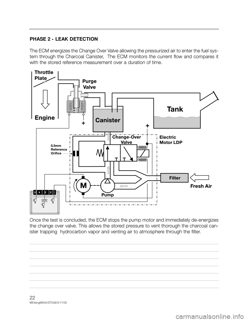
PHASE 2 - LEAK DETECTION
The ECM energizes the Change Over Valve allowing the pressurized air to enter the fuel sys-
tem through the Charcoal Canister, The ECM monitors the current flow and compares it
with the stored reference measurement over a duration of time.
Once the test is concluded, the ECM stops the pump motor and immediately de-energizes
the change over valve. This allows the stored pressure to vent thorough the charcoal can-
ister trapping hydrocarbon vapor and venting air to atmosphere through the filter.
Page 35 of 48
35
M54engMS43/ST036/6/20000
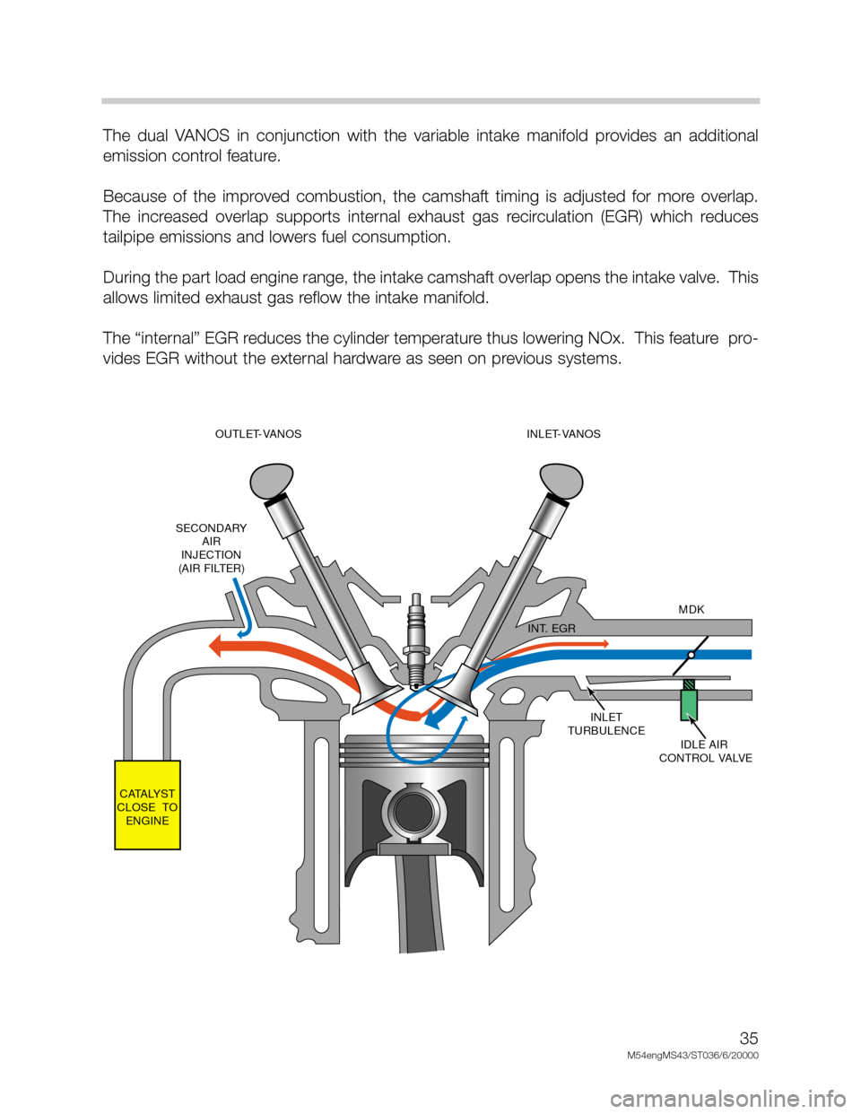
The dual VANOS in conjunction with the variable intake manifold provides an additional
emission control feature.
Because of the improved combustion, the camshaft timing is adjusted for more overlap.
The increased overlap supports internal exhaust gas recirculation (EGR) which reduces
tailpipe emissions and lowers fuel consumption.
During the part load engine range, the intake camshaft overlap opens the intake valve. This
allows limited exhaust gas reflow the intake manifold.
The “internal” EGR reduces the cylinder temperature thus lowering NOx. This feature pro-
vides EGR without the external hardware as seen on previous systems.
INLET
TURBULENCE
IDLE AIR
CONTROL VALVEMDK
INT. EGR
CATALYST
CLOSE TO
ENGINESECONDARY
AIR
INJECTION
(AIR FILTER)OUTLET-VANOS
(228/80-105)INLET-VANOS
(228/80-120)
Page 38 of 48
38
M54engMS43/ST036/6/2000
The Secondary Air Injection System is monitored via the use of the pre-catalyst oxygen sen-
sor(s). Once the air pump is active and is air injected into the system the signal at the oxy-
gen sensor will reflect a lean condition. If the oxygen sensor signal does not change with-
in a predefined time a fault will be set and identify the faulty bank(s). If after completing the
next cold start and a fault is again present the "Service Engine Soon" light will be illuminat-
ed.
Example: Secondary Air Injection Monitoring (M54-Siemens System)
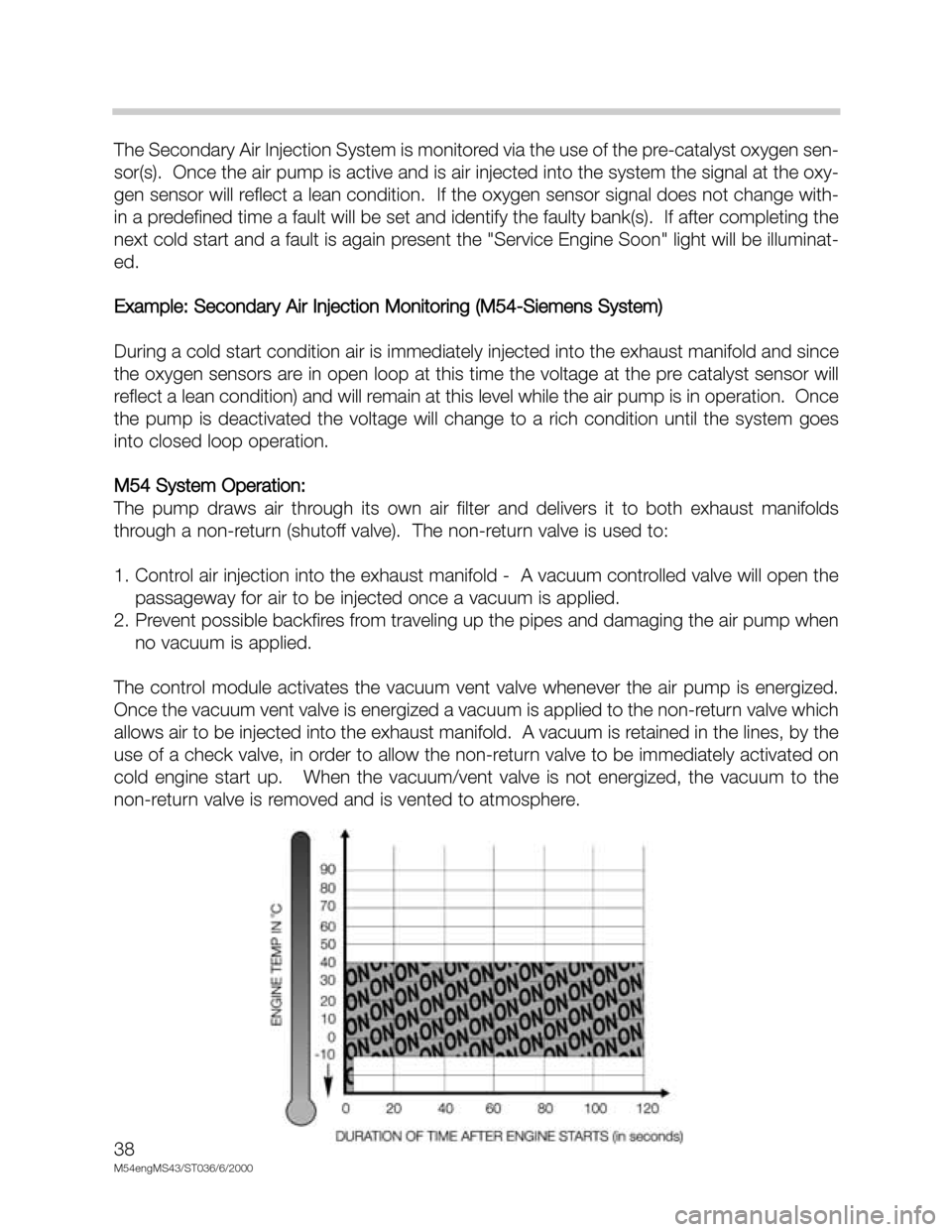
During a cold start condition air is immediately injected into the exhaust manifold and since
the oxygen sensors are in open loop at this time the voltage at the pre catalyst sensor will
reflect a lean condition) and will remain at this level while the air pump is in operation. Once
the pump is deactivated the voltage will change to a rich condition until the system goes
into closed loop operation.
M54 System Operation:
The pump draws air through its own air filter and delivers it to both exhaust manifolds
through a non-return (shutoff valve). The non-return valve is used to:
1. Control air injection into the exhaust manifold - A vacuum controlled valve will open the
passageway for air to be injected once a vacuum is applied.
2. Prevent possible backfires from traveling up the pipes and damaging the air pump when
no vacuum is applied.
The control module activates the vacuum vent valve whenever the air pump is energized.
Once the vacuum vent valve is energized a vacuum is applied to the non-return valve which
allows air to be injected into the exhaust manifold. A vacuum is retained in the lines, by the
use of a check valve, in order to allow the non-return valve to be immediately activated on
cold engine start up. When the vacuum/vent valve is not energized, the vacuum to the
non-return valve is removed and is vented to atmosphere.