wheel BUICK ENCLAVE 2010 Workshop Manual
[x] Cancel search | Manufacturer: BUICK, Model Year: 2010, Model line: ENCLAVE, Model: BUICK ENCLAVE 2010Pages: 438, PDF Size: 2.47 MB
Page 300 of 438
10-2 Vehicle Care
Tire Inspection . . . . . . . . . . . . . . 10-50
Tire Rotation . . . . . . . . . . . . . . . 10-50
When It Is Time for NewTires . . . . . . . . . . . . . . . . . . . . . . 10-51
Buying New Tires . . . . . . . . . . . 10-52
Different Size Tires and
Wheels . . . . . . . . . . . . . . . . . . . 10-54
Uniform Tire Quality Grading . . . . . . . . . . . . . . . . . . . 10-54
Wheel Alignment and Tire Balance . . . . . . . . . . . . . . . . . . . 10-56
Wheel Replacement . . . . . . . . 10-56
Tire Chains . . . . . . . . . . . . . . . . . 10-57
If a Tire Goes Flat . . . . . . . . . . 10-58
Tire Sealant and Compressor Kit . . . . . . . . . . . 10-60
Storing the Tire Sealant and Compressor Kit . . . . . . . . . . . 10-68
Tire Changing . . . . . . . . . . . . . . 10-68
Secondary Latch System . . . 10-78
Compact Spare Tire . . . . . . . . 10-80Jump Starting
Jump Starting . . . . . . . . . . . . . . 10-81
Towing
Towing the Vehicle . . . . . . . . . 10-85
Recreational Vehicle Towing . . . . . . . . . . . . . . . . . . . . 10-85
Appearance Care
Exterior Care . . . . . . . . . . . . . . . 10-88
Interior Care . . . . . . . . . . . . . . . . 10-92
Floor Mats . . . . . . . . . . . . . . . . . . 10-95
General Information
For service and parts needs, visit
your dealer/retailer. You will receive
genuine GM parts and GM-trained
and supported service people.
Genuine GM parts have one of
these marks:
Page 321 of 438
Vehicle Care 10-23
Some driving conditions or climates
can cause a brake squeal when the
brakes are first applied or lightly
applied. This does not mean
something is wrong with the brakes.
Properly torqued wheel nuts are
necessary to help prevent brake
pulsation. When tires are rotated,
inspect brake pads for wear and
evenly tighten wheel nuts in the
proper sequence to torque
specifications inCapacities and
Specifications on page 12‑2.
Brake linings should always be
replaced as complete axle sets.
Brake Pedal Travel
See your dealer/retailer if the brake
pedal does not return to normal
height, or if there is a rapid increase
in pedal travel. This could be a sign
that brake service might be
required.
Brake Adjustment
Every time the brakes are applied,
with or without the vehicle moving,
the brakes adjust for wear.
Replacing Brake System Parts
The braking system on a vehicle is
complex. Its many parts have to be
of top quality and work well together
if the vehicle is to have really good
braking. The vehicle was designed
and tested with top-quality brake
parts. When parts of the braking
system are replaced, be sure to get
new, approved replacement parts.
If this is not done, the brakes might
not work properly. For example,
installing disc brake pads that are
wrong for the vehicle, can change
the balance between the front and
rear brakes —for the worse. The
braking performance expected can
change in many other ways if the
wrong replacement brake parts are
installed.
Brake Fluid
The brake master cylinder reservoir
is filled with DOT 3 brake fluid as
indicated on the reservoir cap. See
Engine Compartment Overview
on
page 10‑6for the location of the
reservoir.
There are only two reasons why the
brake fluid level in the reservoir
might go down:
.The brake fluid level goes down
because of normal brake lining
wear. When new linings are
installed, the fluid level goes
back up.
Page 323 of 438
Vehicle Care 10-25
Battery
Refer to the replacement number on
the original battery label when a
new battery is needed.
{DANGER
Battery posts, terminals, and
related accessories contain lead
and lead compounds, chemicals
known to the State of California to
cause cancer and reproductive
harm. Wash hands after handling.
Vehicle Storage
{WARNING
Batteries have acid that can burn
you and gas that can explode.
You can be badly hurt if you are
not careful. SeeJump Starting
on
page 10‑81
for tips on working
around a battery without
getting hurt. Infrequent Usage: Remove the
black, negative (−) cable from the
battery to keep the battery from
running down.
Extended Storage: Remove the
black, negative (−) cable from the
battery or use a battery trickle
charger.
All-Wheel Drive
It is not necessary to check the
all–wheel drive lubricant levels.
A fluid leak is the only reason for
fluid loss. If a leak occurs, take the
vehicle to the dealer/retailer as soon
as possible.
Starter Switch Check
{WARNING
When you are doing this
inspection, the vehicle could
move suddenly. If the vehicle
moves, you or others could be
injured.
1. Before starting this check, be sure there is enough room
around the vehicle.
2. Firmly apply both the parking brake and the regular brake.
See Parking Brake
on
page 9‑27.
Do not use the accelerator
pedal, and be ready to turn off
the engine immediately if it
starts.
3. Try to start the engine in each gear. The vehicle should start
only in P (Park) or N (Neutral).
If the vehicle starts in any other
position, contact your dealer/
retailer for service.
Page 331 of 438
Vehicle Care 10-33
FusesUsage
A/C CLUTCH Air Conditioning
Clutch
ABS MTR Antilock Braking
System (ABS)
Motor
AFS Adaptive Forward
Lighting System
AIRBAG Airbag System
AUX POWER Auxiliary Power
AUX VACPUMP Auxiliary
Vacuum Pump
AWD All-Wheel-Drive
System
BATT 1 Battery 1
BATT 2 Battery 2
BATT 3 Battery 3
ECM Engine Control
Module
ECM 1 Engine Control
Module 1 Fuses
Usage
EMISSION 1 Emission 1
EMISSION 2 Emission 2
EVEN COILS Even Injector Coils FAN 1 Cooling Fan 1
FAN 2 Cooling Fan 2
FOG LAMP Fog Lamps
FSCM Fuel System
Control Module
HORN Horn
HTD MIR Heated Outside
Rearview Mirror
HVAC BLWR Heating,
Ventilation and
Air Conditioning
Blower
LT HI BEAM Left High-Beam
Headlamp
LT LO BEAM Left Low-Beam
Headlamp
LT PRK Left Parking Lamp Fuses
Usage
LT TRLR
STOP/TRN Trailer Left
Stoplamp and
Turn Signal
ODD COILS Odd Injector Coils
PCM IGN Powertrain Control
Module Ignition
PWR L/GATE Power Liftgate PWR
OUTLET Power Outlet
REAR
CAMERA Rear Camera
RR APO Rear Accessory
Power Outlet
RR DEFOG Rear Defogger
RR HVAC Rear Climate
Control System
RT HI BEAM Right High-Beam
Headlamp
RT LO BEAM Right Low-Beam
Headlamp
Page 334 of 438

10-36 Vehicle Care
FusesUsage
HVAC Heating,
Ventilation and
Air Conditioning
INADV/
PWR/LED Inadvertent
Power LED
INFOTMNT Infotainment
LT/TRN/SIG Driver Side Turn
Signal
MSM Memory Seat
Module
PDM Power Mirrors,
Liftgate Release
PWR MODE Power Mode
PWR/MIR Power Mirrors RDO Radio
REAR WPR Rear Wiper
RT/TRN/SIG Passenger Side
Turn Signal
SPARE Spare
STR/WHL/ ILLUM Steering Wheel
Illumination
Relay Side Relays Usage
LT/PWR/ SEAT Driver Side Power
Seat Relay
RT/PWR/ SEAT Passenger Side
Power Seat Relay
PWR/WNDW Power Windows
Relay
PWR/
COLUMN Power Steering
Column Relay
L/GATE Liftgate Relay
LCK Power Lock Relay
REAR/WSW Rear Window
Washer Relay
UNLCK Power Unlock
Relay
Page 335 of 438
Vehicle Care 10-37
RelaysUsage
DRL2 Daytime Running
Lamps 2 Relay
LT/UNLCK Driver Side Unlock
Relay
DRL Daytime Running
Lamps Relay
SPARE Spare
FRT/WSW Front Windshield
Washer RelayWheels and Tires
Tires
Your new vehicle comes with
high-quality tires made by a
leading tire manufacturer. If you
ever have questions about your
tire warranty and where to
obtain service, see your vehicle
Warranty booklet for details.
For additional information refer
to the tire manufacturer.
{WARNING
Poorly maintained and improperly
used tires are dangerous.
.Overloading your tires can
cause overheating as a result
of too much flexing. You
could have an air-out and a
serious accident. See
Vehicle
Load Limits on page 9‑12.
(Continued)
WARNING (Continued)
.Underinflated tires pose the
same danger as overloaded
tires. The resulting accident
could cause serious injury.
Check all tires frequently to
maintain the recommended
pressure. Tire pressure
should be checked when your
tires are cold. See Tire
Pressure on page 10‑44.
.Overinflated tires are more
likely to be cut, punctured or
broken by a sudden
impact —such as when you
hit a pothole. Keep tires at
the recommended pressure.
.Worn, old tires can cause
accidents. If your tread is
badly worn, or if your tires
have been damaged,
replace them.
Page 339 of 438
Vehicle Care 10-41
(E) Rim Diameter:Diameter of
the wheel in inches.
(F) Service Description
:These
characters represent the load
index and speed rating of the
tire. The load index represents
the load carry capacity a tire is
certified to carry. The speed
rating is the maximum speed a
tire is certified to carry a load.
Tire Terminology and
Definitions
Air Pressure:The amount of
air inside the tire pressing
outward on each square inch of
the tire. Air pressure is
expressed in psi (pounds per
square inch) or kPa (kilopascal). Accessory Weight
:This
means the combined weight
of optional accessories.
Some examples of optional
accessories are, automatic
transmission, power steering,
power brakes, power windows,
power seats, and air
conditioning.
Aspect Ratio
:The relationship
of a tire's height to its width.
Belt
:A rubber coated layer of
cords that is located between
the plies and the tread. Cords
may be made from steel or other
reinforcing materials.
Bead
:The tire bead contains
steel wires wrapped by steel
cords that hold the tire onto
the rim. Bias Ply Tire
:A pneumatic tire
in which the plies are laid at
alternate angles less than
90 degrees to the centerline of
the tread.
Cold Tire Pressure
:The
amount of air pressure in a tire,
measured in psi (pounds per
square inch) or kPa (kilopascal)
before a tire has built up heat
from driving. See Tire Pressure
on page 10‑44.
Curb Weight
:The weight of a
motor vehicle with standard and
optional equipment including the
maximum capacity of fuel, oil,
and coolant, but without
passengers and cargo.
Page 344 of 438
10-46 Vehicle Care
Please note that the TPMS is
not a substitute for proper tire
maintenance, and it is the driver's
responsibility to maintain correct tire
pressure, even if under-inflation has
not reached the level to trigger
illumination of the TPMS low tire
pressure telltale.
Your vehicle has also been
equipped with a TPMS malfunction
indicator to indicate when the
system is not operating properly.
The TPMS malfunction indicator is
combined with the low tire pressure
telltale. When the system detects a
malfunction, the telltale will flash for
approximately one minute and then
remain continuously illuminated.
This sequence will continue upon
subsequent vehicle start-ups as
long as the malfunction exists.
When the malfunction indicator is
illuminated, the system may not
be able to detect or signal low
tire pressure as intended.TPMS malfunctions may occur for a
variety of reasons, including the
installation of replacement or
alternate tires or wheels on the
vehicle that prevent the TPMS from
functioning properly. Always check
the TPMS malfunction telltale after
replacing one or more tires or
wheels on your vehicle to ensure
that the replacement or alternate
tires and wheels allow the TPMS to
continue to function properly.
See
Tire Pressure Monitor
Operation
on page 10‑46for
additional information.
Federal Communications
Commission (FCC) and
Industry and Science Canada
See Radio Frequency Statementon
page 13‑16for information
regarding Part 15 of the Federal
Communications Commission (FCC)
Rules and RSS-210/211 of Industry
and Science Canada.
Tire Pressure Monitor
Operation
This vehicle may have a Tire
Pressure Monitor System (TPMS).
The TPMS is designed to warn the
driver when a low tire pressure
condition exists. TPMS sensors are
mounted onto each tire and wheel
assembly, excluding the spare tire
and wheel assembly, if the vehicle
has one. The TPMS sensors
monitor the air pressure in the
vehicle's tires and transmits the tire
pressure readings to a receiver
located in the vehicle.
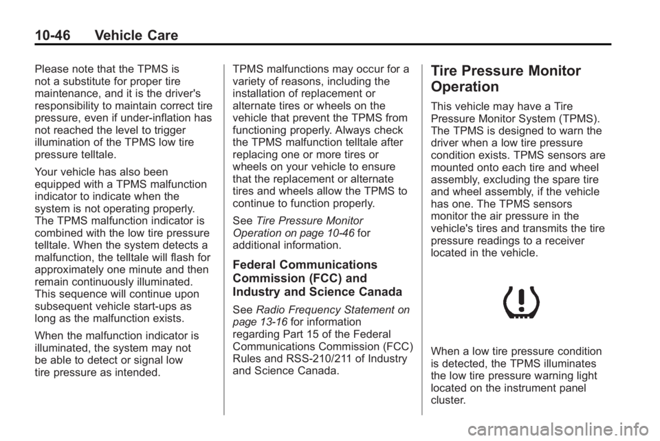
When a low tire pressure condition
is detected, the TPMS illuminates
the low tire pressure warning light
located on the instrument panel
cluster.
Page 346 of 438
10-48 Vehicle Care
TPMS Malfunction Light and
Message
The TPMS will not function properly
if one or more of the TPMS sensors
are missing or inoperable. When the
system detects a malfunction, the
low tire warning light flashes for
about one minute and then stays on
for the remainder of the ignition
cycle. A DIC warning message is
also displayed. The low tire warning
light and DIC warning message
come on at each ignition cycle until
the problem is corrected. Some of
the conditions that can cause the
malfunction light and DIC message
to come on are:
.One of the road tires has been
replaced with the spare tire,
if your vehicle has one. The
spare tire does not have a
TPMS sensor. The TPMS
malfunction light and DIC
message should go off once you
re-install the road tire containing
the TPMS sensor.
.The TPMS sensor matching
process was started but not
completed or not completed
successfully after rotating the
vehicle's tires. The DIC message
and TPMS malfunction light
should go off once the TPMS
sensor matching process is
performed successfully. See
“TPMS Sensor Matching
Process”later in this section.
.One or more TPMS sensors are
missing or damaged. The DIC
message and the TPMS
malfunction light should go off
when the TPMS sensors are
installed and the sensor
matching process is performed
successfully. See your dealer/
retailer for service.
.Replacement tires or wheels do
not match your vehicle's original
equipment tires or wheels. Tires
and wheels other than those
recommended for your vehicle
could prevent the TPMS from
functioning properly. See Buying
New Tires on page 10‑52.
.Operating electronic devices or
being near facilities using radio
wave frequencies similar to the
TPMS could cause the TPMS
sensors to malfunction.
If the TPMS is not functioning it
cannot detect or signal a low tire
condition. See your dealer/retailer
for service if the TPMS malfunction
light and DIC message comes on
and stays on.
TPMS Sensor Matching
Process
Each TPMS sensor has a unique
identification code. Any time you
rotate your vehicle's tires or replace
one or more of the TPMS sensors,
the identification codes will need to
be matched to the new tire/wheel
position. The sensors are matched
to the tire/wheel positions in the
following order: driver side front tire,
passenger side front tire, passenger
side rear tire, and driver side rear
tire using a TPMS diagnostic tool.
See your dealer/retailer for service.
Page 347 of 438

Vehicle Care 10-49
The TPMS sensors can also be
matched to each tire/wheel position
by increasing or decreasing the
tire's air pressure. If increasing the
tire's air pressure, do not exceed
the maximum inflation pressure
indicated on the tire's sidewall.
To decrease air-pressure out of a
tire you can use the pointed end of
the valve cap, a pencil-style air
pressure gage, or a key.
You have two minutes to match the
first tire/wheel position, and
five minutes overall to match all
four tire/wheel positions. If it takes
longer than two minutes, to match
the first tire and wheel, or more than
five minutes to match all four tire
and wheel positions the matching
process stops and you need to
start over.
The TPMS sensor matching process
is outlined below:
1. Set the parking brake.
2. Turn the ignition switch to ON/RUN with the engine off. 3. Press the Remote Keyless Entry
(RKE) transmitter's LOCK and
UNLOCK buttons at the same
time for approximately
five seconds. The horn sounds
twice to signal the receiver is in
relearn mode and TIRE
LEARNING ACTIVE message
displays on the DIC screen.
4. Start with the driver side front tire.
5. Remove the valve cap from the valve cap stem. Activate the
TPMS sensor by increasing or
decreasing the tire's air pressure
for five seconds, or until a horn
chirp sounds. The horn chirp,
which may take up to
30 seconds to sound, confirms
that the sensor identification
code has been matched to this
tire and wheel position.
6. Proceed to the passenger side front tire, and repeat the
procedure in Step 5. 7. Proceed to the passenger side
rear tire, and repeat the
procedure in Step 5.
8. Proceed to the driver side rear tire, and repeat the procedure in
Step 5. The horn sounds two
times to indicate the sensor
identification code has been
matched to the driver side rear
tire, and the TPMS sensor
matching process is no longer
active. The TIRE LEARNING
ACTIVE message on the DIC
display screen goes off.
9. Turn the ignition switch to LOCK/OFF.
10. Set all four tires to the recommended air pressure
level as indicated on the Tire
and Loading Information label.
11. Put the valve caps back on the valve stems.