CADILLAC CTS 2009 2.G Owners Manual
Manufacturer: CADILLAC, Model Year: 2009, Model line: CTS, Model: CADILLAC CTS 2009 2.GPages: 490, PDF Size: 2.68 MB
Page 141 of 490

How OnStar Service Works
The OnStar system can record and transmit vehicle
information. This information is automatically sent to an
OnStar Call Center when the OnStar button is pressed,
the emergency button is pressed, or if the airbags or
AACN system deploy. This information usually includes
the vehicle’s GPS location and, in the event of a crash,
additional information regarding the crash that the vehicle
was involved in (e.g. the direction from which the vehicle
was hit). When the Virtual Advisor feature of OnStar
Hands-Free Calling is used, the vehicle also sends
OnStar the vehicle’s GPS location so they can provide
services where it is located.
OnStar service cannot work unless the vehicle is in a
place where OnStar has an agreement with a wireless
service provider for service in that area. OnStar service
also cannot work unless the vehicle is in a place where
the wireless service provider OnStar has hired for that
area has coverage, network capacity and reception when
the service is needed, and technology that is compatible
with the OnStar service. Not all services are available
everywhere, particularly in remote or enclosed areas, or
at all times.Location information about the vehicle is only available if
the GPS satellite signals are unobstructed and available.
The vehicle must have a working electrical system,
including adequate battery power, for the OnStar
equipment to operate. There are other problems OnStar
cannot control that may prevent OnStar from providing
OnStar service at any particular time or place. Some
examples are damage to important parts of the vehicle in
a crash, hills, tall buildings, tunnels, weather or wireless
phone network congestion.
Your Responsibility
Increase the volume of the radio if the OnStar advisor
cannot be heard. If the light next to the OnStar buttons is
red, the system may not be functioning properly. Press
the OnStar button and request a vehicle diagnostic. If the
light appears clear (no light is appearing), your OnStar
subscription has expired and all services have been
deactivated. Press the OnStar button to con�rm that the
OnStar equipment is active.
2-59
Page 142 of 490

Universal Home Remote
System
The Universal Home Remote System provides a way to
replace up to three hand-held Radio-Frequency (RF)
transmitters used to activate devices such as garage
door openers, security systems, and home lighting.
This device complies with Part 15 of the FCC Rules.
Operation is subject to the following two conditions:
1. This device may not cause harmful interference.
2. This device must accept any interference received,
including interference that may cause undesired
operation.
This device complies with RSS-210 of Industry Canada.
Operation is subject to the following two conditions:
1. This device may not cause interference.
2. This device must accept any interference received,
including interference that may cause undesired
operation of the device.
Changes or modi�cations to this system by other than
an authorized service facility could void authorization to
use this equipment.
Universal Home Remote System
Operation (With One Triangular LED)
If there is one triangular Light Emitting Diode (LED)
indicator light above the Universal Home Remote
buttons, follow the instructions below.
This system provides a way to replace up to three remote
control transmitters used to activate devices such as
garage door openers, security systems, and home
automation devices.
Do not use the Universal Home Remote with any
garage door opener that does not have the stop and
reverse feature. This includes any garage door opener
model manufactured before April 1, 1982.
Read the instructions completely before attempting to
program the Universal Home Remote. Because of
the steps involved, it may be helpful to have another
person available to assist you in the programming
the Universal Home Remote.
2-60
Page 143 of 490

Keep the original hand-held transmitter for use in other
vehicles as well as for future Universal Home Remote
programming. It is also recommended that upon the
sale of the vehicle, the programmed Universal Home
Remote buttons should be erased for security purposes.
See “Erasing Universal Home Remote Buttons” later in
this section.
When programming a garage door, park outside of the
garage. Park directly in line with and facing the garage
door opener motor-head or gate motor-head. Be sure that
people and objects are clear of the garage door or gate
that is being programmed.
It is recommended that a new battery be installed in
your hand-held transmitter for quicker and more
accurate transmission of the radio-frequency signal.
Programming the Universal Home
Remote System
For questions or help programming the Universal
Home Remote System, call 1-800-355-3515 or
go to www.homelink.com.
Programming a garage door opener involves
time-sensitive actions, so read the entire procedure
before starting. Otherwise, the device will time out
and the procedure will have to be repeated.To program up to three devices:
1. From inside the vehicle, press and hold down the
two outside buttons at the same time, releasing
only when the Universal Home Remote indicator
light begins to �ash, after 20 seconds. This step
will erase the factory settings or all previously
programmed buttons.
Do not hold down the buttons for longer than
30 seconds and do not repeat this step to program
the remaining two Universal Home Remote buttons.
2. Hold the end of your hand-held transmitter about
1 to 3 inches (3 to 8 cm) away from the Universal
Home Remote buttons while keeping the indicator
light in view. The hand-held transmitter was supplied
by the manufacturer of your garage door opener
receiver (motor head unit).
2-61
Page 144 of 490
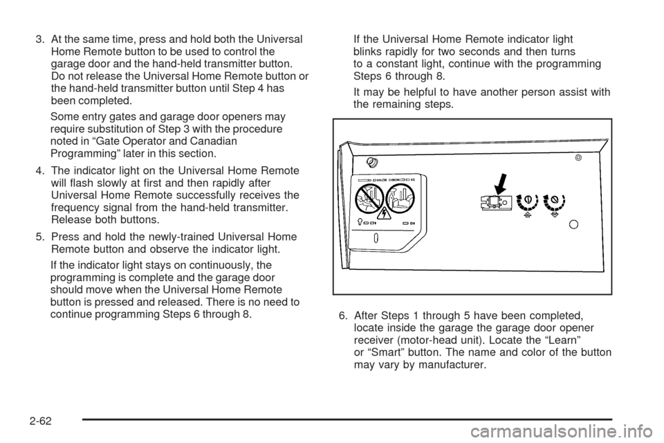
3. At the same time, press and hold both the Universal
Home Remote button to be used to control the
garage door and the hand-held transmitter button.
Do not release the Universal Home Remote button or
the hand-held transmitter button until Step 4 has
been completed.
Some entry gates and garage door openers may
require substitution of Step 3 with the procedure
noted in “Gate Operator and Canadian
Programming” later in this section.
4. The indicator light on the Universal Home Remote
will �ash slowly at �rst and then rapidly after
Universal Home Remote successfully receives the
frequency signal from the hand-held transmitter.
Release both buttons.
5. Press and hold the newly-trained Universal Home
Remote button and observe the indicator light.
If the indicator light stays on continuously, the
programming is complete and the garage door
should move when the Universal Home Remote
button is pressed and released. There is no need to
continue programming Steps 6 through 8.If the Universal Home Remote indicator light
blinks rapidly for two seconds and then turns
to a constant light, continue with the programming
Steps 6 through 8.
It may be helpful to have another person assist with
the remaining steps.
6. After Steps 1 through 5 have been completed,
locate inside the garage the garage door opener
receiver (motor-head unit). Locate the “Learn”
or “Smart” button. The name and color of the button
may vary by manufacturer.
2-62
Page 145 of 490

7. Firmly press and release the “Learn” or “Smart”
button. After you press this button, you will have
30 seconds to complete Step 8.
8. Immediately return to the vehicle. Firmly press and
hold the Universal Home Remote button, chosen in
Step 3 to control the garage door, for two seconds,
and then release it. If the garage door does not
move, press and hold the same button a second time
for two seconds, and then release it. Again, if the
door does not move, press and hold the same button
a third time for two seconds, and then release.
The Universal Home Remote should now activate
the garage door.
To program the remaining two Universal Home Remote
buttons, begin with Step 2 of “Programming the Universal
Home Remote System.” Do not repeat Step 1, as this will
erase all previous programming from the Universal Home
Remote buttons.Gate Operator and Canadian
Programming
If you have questions or need help programming the
Universal Home Remote System, call 1-800-355-3515
or go to www.homelink.com.
Canadian radio-frequency laws require transmitter
signals to time out or quit after several seconds of
transmission. This may not be long enough for Universal
Home Remote to pick up the signal during programming.
Similarly, some U.S. gate operators are manufactured
to time out in the same manner.
If you live in Canada, or you are having difficulty
programming a gate operator or garage door opener by
using the “Programming Universal Home Remote”
procedures, regardless of where you live, replace
Step 3 under “Programming Universal Home Remote”
with the following:
Continue to press and hold the Universal Home Remote
button while you press and release every two seconds
(cycle) the hand-held transmitter button until the
frequency signal has been successfully accepted by the
Universal Home Remote. The Universal Home Remote
indicator light will �ash slowly at �rst and then rapidly.
Proceed with Step 4 under “Programming Universal
Home Remote” to complete.
2-63
Page 146 of 490

Using Universal Home Remote
Press and hold the appropriate Universal Home Remote
button for at least half of a second. The indicator light
will come on while the signal is being transmitted.
Erasing Universal Home Remote
Buttons
The programmed buttons should be erased when the
vehicle is sold or the lease ends.
To erase all programmed buttons on the Universal
Home Remote device:
1. Press and hold down the two outside buttons until
the indicator light begins to �ash, after 20 seconds.
2. Release both buttons.
Reprogramming a Single Universal
Home Remote Button
To reprogram any of the three Universal Home Remote
buttons, repeat the programming instructions earlier
in this section, beginning with Step 2.
For help or information on the Universal Home Remote
System, call the customer assistance phone number
underCustomer Assistance Offices on page 7-6.
Storage Areas
Glove Box
To open, press the button. Use the key to lock and
unlock. The glove box has a shelf that can be removed
by pulling it out.
Cupholders
The vehicle has cupholders located in front of the center
console. Push down on the cover to open. There are also
cupholders in the rear center armrest. Pull the armrest
down to use.
2-64
Page 147 of 490
Instrument Panel Storage
Your vehicle has a storage area located below the
climate control systems. To access, push on the lid.
Center Console Storage
Your vehicle has a center console with an upper and
lower storage area. To access the upper storage area,
lift the driver side lever on the front of the console and
lift the cover. To access the lower storage area, lift the
passenger side lever on the center console. There is an
additional storage area behind the center console.
To access, push the cover.
Convenience Net
Your vehicle may have a convenience net in the rear of
the vehicle. Put small loads behind the net. It can also be
positioned into an envelope style to hold smaller items.
The net is not for heavier loads. Store items as far
forward as you can.
Sunroof
If the vehicle has a power sunroof it will only operate
when the ignition is turned on, or in ACC/ACCESSORY,
or when Retained Accessory Power (RAP) is active.
SeeRetained Accessory Power (RAP) on page 2-33.
The sunroof switches are located on the overhead
console.
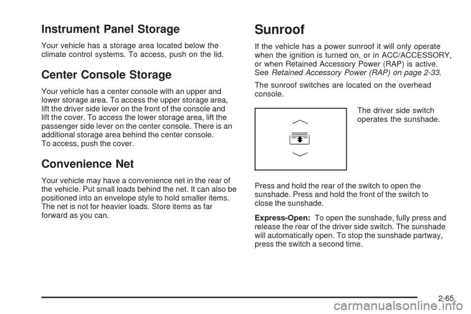
The driver side switch
operates the sunshade.
Press and hold the rear of the switch to open the
sunshade. Press and hold the front of the switch to
close the sunshade.
Express-Open:To open the sunshade, fully press and
release the rear of the driver side switch. The sunshade
will automatically open. To stop the sunshade partway,
press the switch a second time.
2-65
Page 148 of 490
Express-Close:To close the sunshade, fully press and
release the front of the driver side switch. The sunshade
will automatically close. To stop the sunshade partway,
press the switch a second time.
The sunshade will open automatically with the sunroof,
but can also be opened manually.
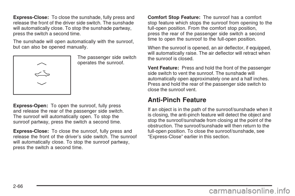
The passenger side switch
operates the sunroof.
Express-Open:To open the sunroof, fully press
and release the rear of the passenger side switch.
The sunroof will automatically open. To stop the
sunroof partway, press the switch a second time.
Express-Close:To close the sunroof, fully press and
release the front of the driver’s side switch. The sunroof
will automatically close. To stop the sunroof partway,
press the switch a second time.Comfort Stop Feature:The sunroof has a comfort
stop feature which stops the sunroof from opening to the
full-open position. From the comfort stop position,
press the rear of the passenger side switch a second
time to open the sunroof to the full-open position.
When the sunroof is opened, an air de�ector, if equipped,
will automatically raise. The air de�ector will retract when
the sunroof is closed.
Vent Feature:Press and hold the front of the passenger
side switch to vent the sunroof. The sunshade will
automatically open approximately one and a half inches.
Press and hold the rear of the passenger side switch to
close the sunroof vent.
Anti-Pinch Feature
If an object is in the path of the sunroof/sunshade when it
is closing, the anti-pinch feature will detect the object and
stop the sunroof/sunshade from closing at the point of the
obstruction. The sunroof/sunshade will then return to the
full-open position. To close the sunroof/sunshade, see
“Express-Close” earlier in this section.
2-66
Page 149 of 490
Instrument Panel Overview...............................3-4
Hazard Warning Flashers................................3-6
Horn .............................................................3-6
Tilt and Telescopic Steering Wheel...................3-6
Power Tilt Wheel and Telescopic Steering
Column......................................................3-7
Turn Signal/Multifunction Lever.........................3-7
Turn and Lane-Change Signals........................3-8
Headlamp High/Low-Beam Changer..................3-8
Flash-to-Pass.................................................3-9
Windshield Wipers..........................................3-9
Rainsense™ Wipers......................................3-10
Windshield Washer.......................................3-12
Headlamp Washer........................................3-13
Cruise Control..............................................3-14
Headlamps..................................................3-17
Wiper Activated Headlamps............................3-17
Headlamps on Reminder................................3-17
Daytime Running Lamps (DRL).......................3-18
Adaptive Forward Lighting System...................3-19
Fog Lamps ..................................................3-19
Exterior Lighting Battery Saver........................3-20
Instrument Panel Brightness...........................3-20
Entry Lighting...............................................3-20
Parade Dimming...........................................3-20
Reading Lamps............................................3-21
Electric Power Management...........................3-21Battery Run-Down Protection..........................3-22
Accessory Power Outlet(s).............................3-22
Ashtray(s) and Cigarette Lighter......................3-23
Analog Clock...............................................3-23
Climate Controls............................................3-24
Dual Climate Control System..........................3-24
Outlet Adjustment.........................................3-29
Passenger Compartment Air Filter...................3-29
Warning Lights, Gages, and Indicators............3-30
Instrument Panel Cluster................................3-31
Speedometer and Odometer...........................3-33
Trip Odometers............................................3-33
Tachometer.................................................3-34
Engine Speed Limiter....................................3-34
Safety Belt Reminders...................................3-35
Airbag Readiness Light..................................3-36
Passenger Airbag Status Indicator...................3-37
Charging System Light..................................3-38
Up-Shift Light...............................................3-38
Brake System Warning Light..........................3-39
Antilock Brake System (ABS) Warning Light.....3-40
StabiliTrak
®/Traction Control System (TCS)
Warning Light...........................................3-41
Engine Coolant Temperature Warning Light......3-41
Engine Coolant Temperature Gage..................3-42
Tire Pressure Light.......................................3-42
Section 3 Instrument Panel
3-1
Page 150 of 490
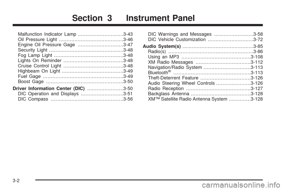
Malfunction Indicator Lamp.............................3-43
Oil Pressure Light.........................................3-46
Engine Oil Pressure Gage.............................3-47
Security Light...............................................3-48
Fog Lamp Light............................................3-48
Lights On Reminder......................................3-48
Cruise Control Light......................................3-48
Highbeam On Light.......................................3-49
Fuel Gage...................................................3-49
Boost Gage.................................................3-50
Driver Information Center (DIC).......................3-50
DIC Operation and Displays...........................3-51
DIC Compass..............................................3-56DIC Warnings and Messages.........................3-58
DIC Vehicle Customization.............................3-72
Audio System(s).............................................3-85
Radio(s)......................................................3-86
Using an MP3............................................3-108
XM Radio Messages...................................3-112
Navigation/Radio System..............................3-113
Bluetooth
®.................................................3-113
Theft-Deterrent Feature................................3-126
Audio Steering Wheel Controls......................3-126
Radio Reception.........................................3-127
Backglass Antenna......................................3-128
XM™ Satellite Radio Antenna System..............3-128
Section 3 Instrument Panel
3-2