light CADILLAC ESCALADE 2010 3.G Service Manual
[x] Cancel search | Manufacturer: CADILLAC, Model Year: 2010, Model line: ESCALADE, Model: CADILLAC ESCALADE 2010 3.GPages: 616, PDF Size: 39.41 MB
Page 176 of 616

The delay that is received after shifting out ofR (Reverse) is approximately 10 seconds. The delaycan be cancelled by performing one of the following:
.Pressing a hard key on the navigation system.
.Shifting in to P (Park).
.Reach a vehicle speed of 7 mph (11 km/h).
There is a message on the rear vision camera screenthat states“Check Surroundings for Safety”.
Adjusting the Brightness and Contrast of
the Screen
To adjust the brightness and contrast of the screen,press the CONFIG hard key while the rear visioncamera image is on the display. Any adjustments madewill only affect the rear vision camera screen.
](Brightness) :Touch the + (plus) or–(minus)screen buttons to increase or decrease the brightnessof the screen.
_(Contrast) :Touch the + (plus) or–(minus) screenbuttons to increase or decrease the contrast ofthe screen.
Symbols
The navigation system may have a feature that lets thedriver view symbols on the navigation screen whileusing the rear vision camera. The Ultrasonic Rear ParkAssist (URPA) system must not be disabled to use thecaution symbols. If URPA has been disabled and thesymbols have been turned on, the Rear Parking AssistSymbols Unavailable error message may display. SeeUltrasonic Rear Parking Assist (URPA) on page 3!46.
The symbols appear when an object has been detectedby the URPA system. The symbol may cover the objectwhen viewing the navigation screen.
To turn the symbols on or off:
1. Make sure that URPA has not been disabled.
2. Shift into P (Park).
3. Press the CONFIG hard key to enter the configuremenu options, then press the CONFIG hard keyrepeatedly until Display is selected or touch theDisplay screen button.
4. Select the Rear Camera Options screen button.The Rear Camera Options screen will display.
5. Touch the Symbols screen button. The screenbutton will be highlighted when on.
3-52
Page 179 of 616
When the System Does Not Seem To
Work Properly
The rear vision camera system might not work properlyor display a clear image if:
.The RVC is turned off. See“Turning the RearCamera System On or Off”earlier in this section.
.It is dark.
.The sun or the beam of headlights is shiningdirectly into the camera lens.
.Ice, snow, mud, or anything else builds up on thecamera lens. Clean the lens, rinse it with water,and wipe it with a soft cloth.
.The back of the vehicle is in an accident, theposition and mounting angle of the camera canchange or the camera can be affected. Be sure tohave the camera and its position and mountingangle checked at your dealer/retailer.
Universal Home Remote
System
SeeRadio Frequency Statementon page 9!20forinformation regarding Part 15 of the FederalCommunications Commission (FCC) Rules andRSS-210/211 of Industry and Science Canada.
Universal Home Remote System
Operation (With Three Round LED)
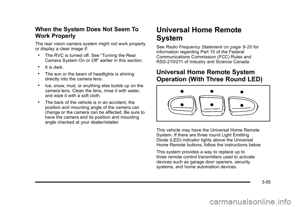
This vehicle may have the Universal Home RemoteSystem. If there are three round Light EmittingDiode (LED) indicator lights above the UniversalHome Remote buttons, follow the instructions below.
This system provides a way to replace up tothree remote control transmitters used to activatedevices such as garage door openers, securitysystems, and home automation devices.
3-55
Page 181 of 616
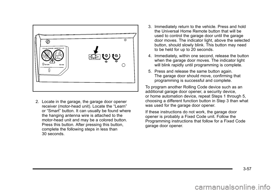
2. Locate in the garage, the garage door openerreceiver (motor-head unit). Locate the“Learn”or“Smart”button. It can usually be found wherethe hanging antenna wire is attached to themotor-head unit and may be a colored button.Press this button. After pressing this button,complete the following steps in less than30 seconds.
3. Immediately return to the vehicle. Press and holdthe Universal Home Remote button that will beused to control the garage door until the garagedoor moves. The indicator light, above the selectedbutton, should slowly blink. This button may needto be held for up to 20 seconds.
4. Immediately, within one second, release the buttonwhen the garage door moves. The indicator lightwill blink rapidly until programming is complete.
5. Press and release the same button again.The garage door should move, confirming thatprogramming is successful and complete.
To program another Rolling Code device such as anadditional garage door opener, a security device,or home automation device, repeat Steps 1 through 5,choosing a different function button in Step 3 than whatwas used for the garage door opener.
If these instructions do not work, the garage dooropener is probably a Fixed Code unit. Follow theProgramming instructions that follow for a Fixed Codegarage door opener.
3-57
Page 185 of 616
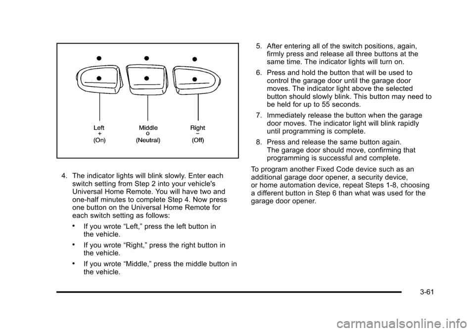
4. The indicator lights will blink slowly. Enter eachswitch setting from Step 2 into your vehicle'sUniversal Home Remote. You will have two andone-half minutes to complete Step 4. Now pressone button on the Universal Home Remote foreach switch setting as follows:
.If you wrote“Left,”press the left button inthe vehicle.
.If you wrote“Right,”press the right button inthe vehicle.
.If you wrote“Middle,”press the middle button inthe vehicle.
5. After entering all of the switch positions, again,firmly press and release all three buttons at thesame time. The indicator lights will turn on.
6. Press and hold the button that will be used tocontrol the garage door until the garage doormoves. The indicator light above the selectedbutton should slowly blink. This button may need tobe held for up to 55 seconds.
7. Immediately release the button when the garagedoor moves. The indicator light will blink rapidlyuntil programming is complete.
8. Press and release the same button again.The garage door should move, confirming thatprogramming is successful and complete.
To program another Fixed Code device such as anadditional garage door opener, a security device,or home automation device, repeat Steps 1-8, choosinga different button in Step 6 than what was used for thegarage door opener.
3-61
Page 186 of 616
Using Universal Home Remote
Press and hold the appropriate button for at least halfof a second. The indicator light will come on while thesignal is being transmitted.
Reprogramming Universal Home
Remote Buttons
Any of the three buttons can be reprogrammed byrepeating the instructions.
Erasing Universal Home Remote
Buttons
The programmed buttons should be erased when thevehicle is sold or the lease ends.
To erase either Rolling Code or Fixed Code on theUniversal Home Remote device:
1. Press and hold the two outside buttons at thesame time for approximately 20 seconds, until theindicator lights, located directly above the buttons,begin to blink rapidly.
2. Once the indicator lights begin to blink, releaseboth buttons. The codes from all buttons willbe erased.
For help or information on the Universal Home RemoteSystem, call the customer assistance phone numberunderCustomer Assistance Offices on page 9!6.
Storage Areas
Glove Box
Pull the bottom of the glove box handle upward toopen it. Use the key to lock and unlock the glove box.
Cupholders
Cupholders are located in the center console for thefront passengers. Press down on the access doorrelease to open and use the front cupholders. Push thedoor back down to close it. Push down and then backon the front cupholder to remove it for cleaning.
Heated and Cooled Cupholders
For vehicles with heated and cooled cupholders, theseare located in the front center console.
Press down on the access door release button to openthe cupholder door.
3-62
Page 189 of 616
Notice:Loading cargo on the roof rack that weighsmore than 91 kg (200 lbs) or hangs over the rear orsides of the vehicle may damage the vehicle. Loadcargo so that it rests evenly between the crossrails,making sure to fasten cargo securely.
To prevent damage or loss of cargo when driving,check to make sure crossrails and cargo are securelyfastened. Loading cargo on the roof rack will make thevehicle’s center of gravity higher. Avoid high speeds,sudden starts, sharp turns, sudden braking or abruptmaneuvers, otherwise it may result in loss of control.If driving for a long distance, on rough roads, or at highspeeds, occasionally stop the vehicle to make sure thecargo remains in its place.
Do not exceed the maximum vehicle capacity whenloading the vehicle. For more information on vehiclecapacity and loading, seeLoading the Vehicleonpage 6!32.
To prevent damage or loss of cargo, check now andthen to make sure the luggage and cargo are stillsecurely fastened.
Be sure the cargo is properly loaded.
.If small heavy objects are placed on the roof, placethe load in the area over the rear wheels (behindthe rear side door on extended models). If needed,cut a piece of 3/8 inch plywood to fit inside thecrossrails and siderails to spread the load.If plywood is used, tie it to the siderail supports.
.Tie the load to the crossrails or the siderailsupports. Use the crossrails only to keep theload from sliding. To move the crossrails, pull outon the latch release handle at each end. Slide thecrossrail to the desired position balancing the forceside to side. Push the release handle back into thelatched position and slide the crossrail back andforth slightly to be sure the latch snaps securelyinto place.
.If needed to carry long items, move the crossrailsas far apart as they will go. Tie the load to thecrossrails and the siderails or siderail supports.Also tie the load to the bumpers. Do not tie theload so tightly that the crossrails or siderailsare damaged.
.After moving a crossrail, be sure it is securelylocked into the siderail.
A Center High-Mounted Stoplamp (CHMSL) is locatedabove the glass or above the rear load doors.
If items are loaded on the roof of the vehicle, careshould be taken not to block or damage theCHMSL unit.
3-65
Page 193 of 616
Section 4 Instrument Panel
Instrument Panel Overview. . . . . . . . . . . . . . . . . . . . . . . . 4-3Hazard Warning Flashers . . . . . . . . . . . . . . . . . . . . . . . 4-3Horn . . . . . . . . . . . . . . . . . . . . . . . . . . . . . . . . . . . . . . . . . . . . 4-3Tilt Wheel . . . . . . . . . . . . . . . . . . . . . . . . . . . . . . . . . . . . . . . 4-3Heated Steering Wheel . . . . . . . . . . . . . . . . . . . . . . . . . 4-4Turn Signal/Multifunction Lever . . . . . . . . . . . . . . . . . . 4-4Turn and Lane-Change Signals . . . . . . . . . . . . . . . . . 4-5Headlamp High/Low-Beam Changer . . . . . . . . . . . . 4-5Flash-to-Pass . . . . . . . . . . . . . . . . . . . . . . . . . . . . . . . . . . . 4-6Windshield Wipers . . . . . . . . . . . . . . . . . . . . . . . . . . . . . . 4-6Windshield Washer . . . . . . . . . . . . . . . . . . . . . . . . . . . . . 4-7Rear Window Wiper/Washer . . . . . . . . . . . . . . . . . . . . 4-7Cruise Control . . . . . . . . . . . . . . . . . . . . . . . . . . . . . . . . . . 4-8Exterior Lamps . . . . . . . . . . . . . . . . . . . . . . . . . . . . . . . . . 4-11Headlamps on Reminder . . . . . . . . . . . . . . . . . . . . . . 4-15Daytime Running Lamps (DRL) . . . . . . . . . . . . . . . . 4-15Automatic Headlamp System . . . . . . . . . . . . . . . . . . 4-15Fog Lamps . . . . . . . . . . . . . . . . . . . . . . . . . . . . . . . . . . . . 4-16Instrument Panel Brightness . . . . . . . . . . . . . . . . . . . 4-16Dome Lamps . . . . . . . . . . . . . . . . . . . . . . . . . . . . . . . . . . 4-17Dome Lamp Override . . . . . . . . . . . . . . . . . . . . . . . . . . 4-17Entry Lighting . . . . . . . . . . . . . . . . . . . . . . . . . . . . . . . . . . 4-17Exit Lighting . . . . . . . . . . . . . . . . . . . . . . . . . . . . . . . . . . . 4-17
Reading Lamps . . . . . . . . . . . . . . . . . . . . . . . . . . . . . . . . 4-17Electric Power Management . . . . . . . . . . . . . . . . . . . 4-18Battery Run-Down Protection . . . . . . . . . . . . . . . . . . 4-18Accessory Power Outlet(s) . . . . . . . . . . . . . . . . . . . . . 4-19Ashtray(s) and Cigarette Lighter . . . . . . . . . . . . . . . 4-20Analog Clock . . . . . . . . . . . . . . . . . . . . . . . . . . . . . . . . . . 4-20
Climate Controls. . . . . . . . . . . . . . . . . . . . . . . . . . . . . . . . . . 4-20Dual Automatic Climate Control System . . . . . . . 4-20Outlet Adjustment . . . . . . . . . . . . . . . . . . . . . . . . . . . . . . 4-25Rear Air Conditioning and Heating System andElectronic Climate Controls . . . . . . . . . . . . . . . . . . 4-26
Warning Lights, Gages, and Indicators. . . . . . . . . . 4-27Instrument Panel Cluster . . . . . . . . . . . . . . . . . . . . . . . 4-28Speedometer and Odometer . . . . . . . . . . . . . . . . . . . 4-29Trip Odometer . . . . . . . . . . . . . . . . . . . . . . . . . . . . . . . . . 4-29Tachometer . . . . . . . . . . . . . . . . . . . . . . . . . . . . . . . . . . . . 4-29Safety Belt Reminders . . . . . . . . . . . . . . . . . . . . . . . . . 4-29Airbag Readiness Light . . . . . . . . . . . . . . . . . . . . . . . . 4-30Passenger Airbag Status Indicator . . . . . . . . . . . . . 4-31Charging System Light . . . . . . . . . . . . . . . . . . . . . . . . 4-32Brake System Warning Light . . . . . . . . . . . . . . . . . . . 4-33Antilock Brake System (ABS) Warning Light . . . 4-34
4-1
Page 194 of 616
Section 4 Instrument Panel
StabiliTrak®Indicator Light . . . . . . . . . . . . . . . . . . . . . 4-34Engine Coolant Temperature Gage . . . . . . . . . . . . 4-35Tire Pressure Light . . . . . . . . . . . . . . . . . . . . . . . . . . . . 4-35Malfunction Indicator Lamp . . . . . . . . . . . . . . . . . . . . 4-36Oil Pressure Light . . . . . . . . . . . . . . . . . . . . . . . . . . . . . 4-38Security Light . . . . . . . . . . . . . . . . . . . . . . . . . . . . . . . . . . 4-39Fog Lamp Light . . . . . . . . . . . . . . . . . . . . . . . . . . . . . . . . 4-39Lights On Reminder . . . . . . . . . . . . . . . . . . . . . . . . . . . 4-39Cruise Control Light . . . . . . . . . . . . . . . . . . . . . . . . . . . 4-39Highbeam On Light . . . . . . . . . . . . . . . . . . . . . . . . . . . . 4-40Tow/Haul Mode Light . . . . . . . . . . . . . . . . . . . . . . . . . . 4-40Fuel Gage . . . . . . . . . . . . . . . . . . . . . . . . . . . . . . . . . . . . . 4-40
Driver Information Center (DIC). . . . . . . . . . . . . . . . . . 4-41DIC Operation and Displays . . . . . . . . . . . . . . . . . . . 4-41DIC Compass . . . . . . . . . . . . . . . . . . . . . . . . . . . . . . . . . . 4-47DIC Warnings and Messages . . . . . . . . . . . . . . . . . . 4-48DIC Vehicle Customization . . . . . . . . . . . . . . . . . . . . 4-57
Audio System(s). . . . . . . . . . . . . . . . . . . . . . . . . . . . . . . . . . 4-67Bluetooth®. . . . . . . . . . . . . . . . . . . . . . . . . . . . . . . . . . . . . 4-67Rear Seat Entertainment (RSE) System(Overhead) . . . . . . . . . . . . . . . . . . . . . . . . . . . . . . . . . . 4-77Rear Seat Entertainment (RSE) System(Headrest DVD) . . . . . . . . . . . . . . . . . . . . . . . . . . . . . 4-86Rear Seat Audio (RSA) . . . . . . . . . . . . . . . . . . . . . . . 4-103Theft-Deterrent Feature . . . . . . . . . . . . . . . . . . . . . . 4-105Audio Steering Wheel Controls . . . . . . . . . . . . . . . 4-105Radio Reception . . . . . . . . . . . . . . . . . . . . . . . . . . . . . . 4-107Rear Side Window Antenna . . . . . . . . . . . . . . . . . . 4-108XM™Satellite Radio Antenna System . . . . . . . . 4-108
4-2
Page 196 of 616
Heated Steering Wheel
For vehicles with a heated steering wheel, the buttonfor this feature is located on the steering wheel.
(:Press to turn the heated steering wheel on or off.A light on the button displays when the feature isturned on.
The steering wheel takes about three minutes to startheating.
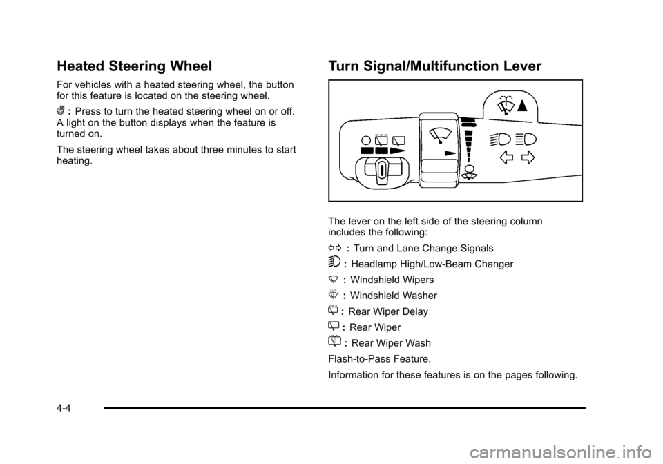
Turn Signal/Multifunction Lever
The lever on the left side of the steering columnincludes the following:
G:Turn and Lane Change Signals
5:Headlamp High/Low-Beam Changer
N:Windshield Wipers
L:Windshield Washer
5:Rear Wiper Delay
Z:Rear Wiper
=:Rear Wiper Wash
Flash-to-Pass Feature.
Information for these features is on the pages following.
4-4
Page 197 of 616
Turn and Lane-Change Signals
An arrow on theinstrument panel clusterflashes in the direction ofthe turn or lane change.
Move the lever all the way up or down to signal a turn.
Raise or lower the lever for less than one seconduntil the arrow starts to flash to signal a lane change.This causes the turn signals to automatically flashthree times. It will flash six times if tow-haul mode isactive. Holding the turn signal lever for more thanone second will cause the turn signals to flash untilyou release the lever.
The lever returns to its starting position whenever it isreleased.
If after signaling a turn or a lane change the arrowsflash rapidly or do not come on, a signal bulb could beburned out.
Have the bulbs replaced. If the bulb is not burned out,check the fuse. SeeFuses and Circuit Breakersonpage 7!108.
Turn Signal On Chime
If the turn signal is left on for more than 3/4 of a mile(1.2 km), a chime will sound at each flash of the turnsignal and the message TURN SIGNAL ON will alsoappear in the Driver Information Control (DIC). To turnthe chime and message off, move the turn signal leverto the off position.
Headlamp High/Low-Beam Changer
53(Headlamp High/Low Beam Changer) :To changethe headlamps from low to high beam, push the levertoward the instrument panel. To return to low-beamheadlamps, pull the multifunction lever toward you.Then release it.
When the high beams areon, this indicator light onthe instrument panelcluster will also be on.
4-5