clock CADILLAC ESCALADE EXT 2010 3.G Owner's Manual
[x] Cancel search | Manufacturer: CADILLAC, Model Year: 2010, Model line: ESCALADE EXT, Model: CADILLAC ESCALADE EXT 2010 3.GPages: 580, PDF Size: 6.23 MB
Page 466 of 580

7. Locate the vertical headlamp aiming screws, whichare under the hood near each headlamp assembly.
The adjustment screw can be turned with a
E8 Torx
®socket.
8. Turn the vertical aiming screw until the headlamp beam is aimed to the horizontal tape line. Turn it
clockwise or counterclockwise to raise or lower the
angle of the beam.
9. Make sure that the light from the headlamp is
positioned at the bottom edge of the horizontal
tape line. The lamp on the left (A) shows the
correct headlamp aim. The lamp on the right (B)
shows the incorrect headlamp aim.
10. Repeat Steps 7 through 9 for the opposite headlamp.
7-52
Page 468 of 580

2. Remove the twoscrews from the
taillamp assembly. 3. Pull the taillamp assembly straight back to remove.
4. Turn the bulb socket counterclockwise to remove it
from the taillamp assembly.
5. Pull the bulb straight out from the socket.
6. Press a new bulb into the socket, insert it into the taillamp assembly and turn the bulb socket
clockwise until it clicks.
7. Reinstall the taillamp assembly and tighten the screws.
7-54
Page 469 of 580

License Plate Lamp
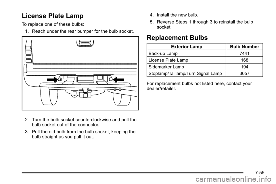
To replace one of these bulbs:1. Reach under the rear bumper for the bulb socket.
2. Turn the bulb socket counterclockwise and pull the bulb socket out of the connector.
3. Pull the old bulb from the bulb socket, keeping the bulb straight as you pull it out. 4. Install the new bulb.
5. Reverse Steps 1 through 3 to reinstall the bulb
socket.
Replacement Bulbs
Exterior Lamp Bulb Number
Back-up Lamp 7441
License Plate Lamp 168
Sidemarker Lamp 194
Stoplamp/Taillamp/Turn Signal Lamp 3057
For replacement bulbs not listed here, contact your
dealer/retailer.
7-55
Page 494 of 580

Removing the Spare Tire and Tools
The jack and the wheel blocks are located under a
cover near the passenger side rear seat.
Rear Seat (Passenger Side) Jack Cover
1. Remove the jack cover by turning the two wing nuts one-quarter turn counterclockwise and pulling
the jack cover off.
A. Wheel Blocks
B. Jack Knob
C. Wing Nut D. Retaining Hook
E. Jack
F. Mounting Bracket
2. Release the jack (E) from the mounting bracket (F) by turning the jack knob (B) on the jack
counterclockwise to release the jack from the
mounting bracket.
7-80
Page 495 of 580

3. Remove the wheel blocks (A) attachedto the jack (E) by turning the wing nut (C)
counterclockwise. Place the wheel blocks where
needed as indicated in previously in this section.
The tools for changing a flat tire are located in the
passenger's side top-box storage unit.
To remove the tools, do the following: 1. Open the top door on the passenger's side top-box storage unit. Use the ignition/door key to unlock it if
it is locked. See Top-Box Storage
on page 3‑76for more information.
2. Remove the black pouch from the storage box. You now have all of the tools you will need to lower
the spare tire and change a flat. To access the spare tire:
A. Spare Tire (Valve
Stem Pointed Down)
B. Hoist Assembly
C. Hoist Cable
D. Tire/Wheel Retainer E. Hoist Shaft
F. Hoist End of Extension Tool G. Hoist Shaft
Access Hole
H. Wheel Wrench I. Jack Handle Extension(s)
J. Spare Tire Lock
7-81
Page 496 of 580

1. Open the hoist shaft access cover on the bumperto access the spare tire lock (J).
2. To remove the spare tire lock, insert the ignition key, turn it clockwise and pull it straight out.
3. Assemble the two jack handle extensions (I) andwheel wrench (H) as shown.
4. Insert the open end ofthe extension (F)
through the hole in the
rear bumper (G) (hoist
shaft access hole).
Be sure the hoist end (F) of the extension connects
to the hoist shaft (E). The ribbed square end of the
extension is used to lower the spare tire.
Do not use the chiseled end of the wheel wrench.
5. Turn the wheel wrench counterclockwise to lower the spare tire to the ground. Continue to turn the
wheel wrench until the spare tire can be pulled out
from under the vehicle.
If the spare tire does not lower to the ground, the
secondary latch is engaged causing the tire not to
lower. See Secondary Latch System
on page 7‑89for more information.
7-82
Page 499 of 580

3. Use the wheelwrench to loosen all
the wheel nuts. Turn
the wheel wrench
counterclockwise to
loosen the wheel nuts.
Do not remove the
wheel nuts yet.
Jacking Locations (Overall View)
A. Front Position
B. Rear Position
{WARNING:
Getting under a vehicle when it is jacked up is
dangerous. If the vehicle slips off the jack, you
could be badly injured or killed. Never get under a
vehicle when it is supported only by a jack.
{WARNING:
Raising your vehicle with the jack improperly
positioned can damage the vehicle and even
make the vehicle fall. To help avoid personal
injury and vehicle damage, be sure to fit the jack
lift head into the proper location before raising the
vehicle.
4. Position the jack under the vehicle as shown.
7-85
Page 500 of 580

Front Position
Front Tire Flat: If the flat tire is on a front tire
of the vehicle, you will need to use the jack
handle (B) and only one jack handle extension (C).
Attach the wheel wrench (D) to the jack handle
extension (C). Attach the jack handle (B) to the
jack (A). Position the jack on the frame behind the
flat tire near the front body mount (E) as shown.
Turn the wheel wrench (D) clockwise to raise the
vehicle. Raise the vehicle far enough off the
ground so there is enough room for the spare tire
to clear the ground.Rear Position
Rear Tire Flat: If the flat tire is on a rear tire of
the vehicle, use the jack handle (B) and both
jack handle extensions (C). Attach the wheel
wrench (D) to the jack handle extensions (C).
Attach the jack handle (B) to the jack (A). Use the
jacking pad (E) provided on the rear axle. Turn the
wheel wrench (D) clockwise to raise the vehicle.
Raise the vehicle far enough off the ground so
there is enough room for the spare tire to clear the
ground.
7-86
Page 502 of 580

{WARNING:
Never use oil or grease on bolts or nuts because
the nuts might come loose. The vehicle's wheel
could fall off, causing a crash.
9. Put the wheel nuts back on with the rounded end of the nuts toward the wheel after mounting the
spare tire.
10. Tighten each wheel nut by hand. Then use the wheel wrench to tighten the wheel nuts until the
wheel is held against the hub.
11. Turn the wheel wrench counterclockwise to lower the vehicle. Lower the jack completely.
{WARNING:
Wheel nuts that are improperly or incorrectly
tightened can cause the wheels to become loose
or come off. The wheel nuts should be tightened
with a torque wrench to the proper torque
specification after replacing. Follow the torque
specification supplied by the aftermarket
(Continued)
WARNING: (Continued)
manufacturer when using accessory locking wheel
nuts. SeeCapacities and Specifications
on
page 7‑112
for original equipment wheel nut
torque specifications.
Notice: Improperly tightened wheel nuts can lead to
brake pulsation and rotor damage. To avoid
expensive brake repairs, evenly tighten the wheel
nuts in the proper sequence and to the proper
torque specification. See Capacities and
Specifications
on page 7‑112for the wheel nut torque
specification.
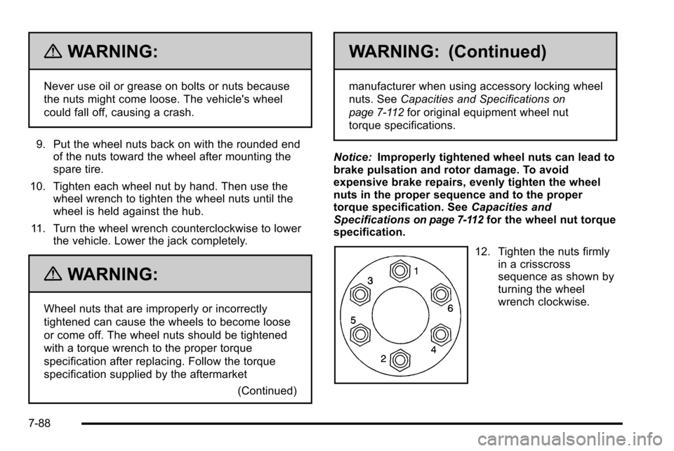
12. Tighten the nuts firmly
in a crisscross
sequence as shown by
turning the wheel
wrench clockwise.
7-88
Page 503 of 580

When you reinstall the regular wheel and tire, you must
also reinstall the center cap. Line the tab on the back of
the tab with the slot in the wheel. Place the cap on the
wheel and press until it snaps into place.
Secondary Latch System
Your vehicle has an underbody-mounted tire hoist
assembly equipped with a secondary latch system. It is
designed to stop the spare tire from suddenly falling off
your vehicle. For the secondary latch to work, the spare
must be installed with the valve stem pointing down.
SeeStoring a Flat or Spare Tire and Tools
on
page 7‑92.
{WARNING:
Before beginning this procedure read all the
instructions. Failure to read and follow the
instructions could damage the hoist assembly and
you and others could get hurt. Read and follow
the instructions listed next. To release the spare tire from the secondary latch:
1. Check under the
vehicle to see if the
cable end is visible.
If the cable is not
visible proceed to
Step 6.
2. If it is visible, first try to tighten the cable by turning the wheel wrench clockwise until you
hear two clicks or feel it skip twice. You cannot
overtighten the cable.
3. Loosen the cable by turning the wrench counterclockwise three or four turns.
4. Repeat this procedure at least two times. If the spare tire lowers to the ground, continue with
Step 5 of Removing the Spare Tire and Tools
on
page 7‑80.
7-89