CHERY TIGGO 2009 Service Repair Manual
Manufacturer: CHERY, Model Year: 2009, Model line: TIGGO, Model: CHERY TIGGO 2009Pages: 1903, PDF Size: 33.38 MB
Page 1201 of 1903
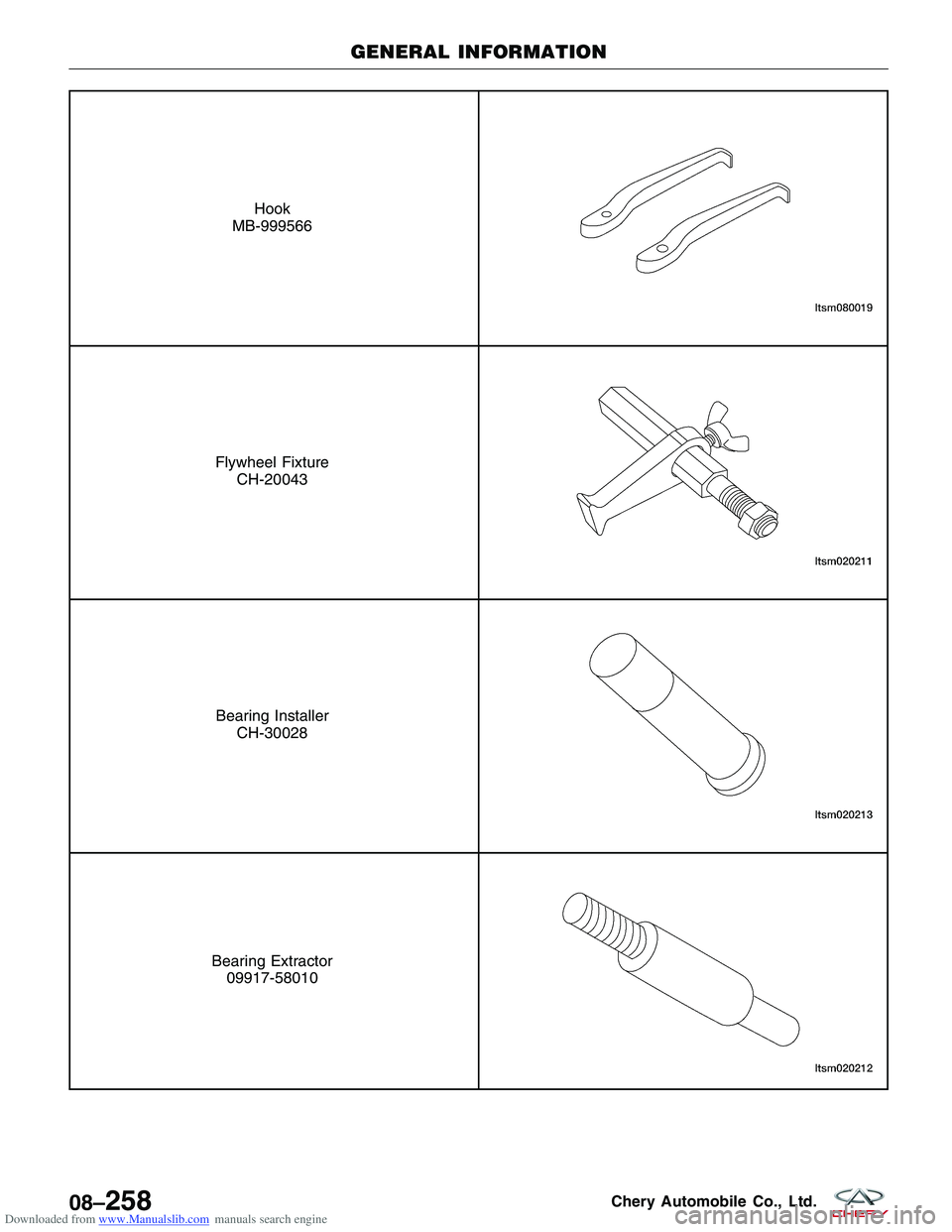
Downloaded from www.Manualslib.com manuals search engine Hook
MB-999566
Flywheel Fixture CH-20043
Bearing InstallerCH-30028
Bearing Extractor09917-58010
GENERAL INFORMATION
08–258Chery Automobile Co., Ltd.
Page 1202 of 1903
Downloaded from www.Manualslib.com manuals search engine DIAGNOSIS & TESTING
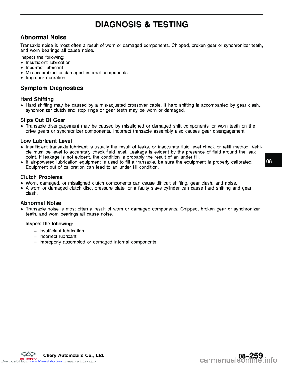
Abnormal Noise
Transaxle noise is most often a result of worn or damaged components. Chipped, broken gear or synchronizer teeth,
and worn bearings all cause noise.
Inspect the following:
•Insufficient lubrication
• Incorrect lubricant
• Mis-assembled or damaged internal components
• Improper operation
Symptom Diagnostics
Hard Shifting
•Hard shifting may be caused by a mis-adjusted crossover cable. If hard shifting is accompanied by gear clash,
synchronizer clutch and stop rings or gear teeth may be worn or damaged.
Slips Out Of Gear
•Transaxle disengagement may be caused by misaligned or damaged shift components, or worn teeth on the
drive gears or synchronizer components. Incorrect transaxle assembly also causes gear disengagement.
Low Lubricant Level
•Insufficient transaxle lubricant is usually the result of leaks, or inaccurate fluid level check or refill method. Vehi-
cle must be level to accurately check fluid level. Leakage is evident by the presence of fluid around the leak
point. If leakage is not evident, the condition is probably the result of an under fill.
• If air-powered lubrication equipment is used to fill a transaxle, be sure the equipment is properly calibrated.
Equipment out of calibration can lead to an under fill condition.
Clutch Problems
•Worn, damaged, or misaligned clutch components can cause difficult shifting, gear clash, and noise.
• A worn or damaged clutch disc, pressure plate, or a faulty slave cylinder can cause hard shifting and gear
clash.
Abnormal Noise
•Transaxle noise is most often a result of worn or damaged components. Chipped, broken gear or synchronizer
teeth, and worn bearings all cause noise.
Inspect the following: � Insufficient lubrication
� Incorrect lubricant
� Improperly assembled or damaged internal components
08
08–259Chery Automobile Co., Ltd.
Page 1203 of 1903

Downloaded from www.Manualslib.com manuals search engine ON-VEHICLE SERVICE
Manual Transaxle Assembly
Removal & Installation
NOTE :
The following special tools are required to perform the repair procedure:
•MB-990938 - Handle
• MB-990935 - Installer Connector
1. Raise and support the vehicle.
2. Disconnect the negative battery cable.
3. Remove the battery and battery tray (See Battery Removal & Installation in Section 05 Starting & Charging).
4. Remove air cleaner and air duct.
5. Drain the cooling system (See Cooling System Draining Procedure in Section 06 Cooling System).
6. Remove the base mounting of the air cleaner housing assembly.
7. Remove the backup lamp switch (2) and vehicle speed sensor (1).
LTSM020226
LTSM030029
08–260Chery Automobile Co., Ltd.
Page 1204 of 1903
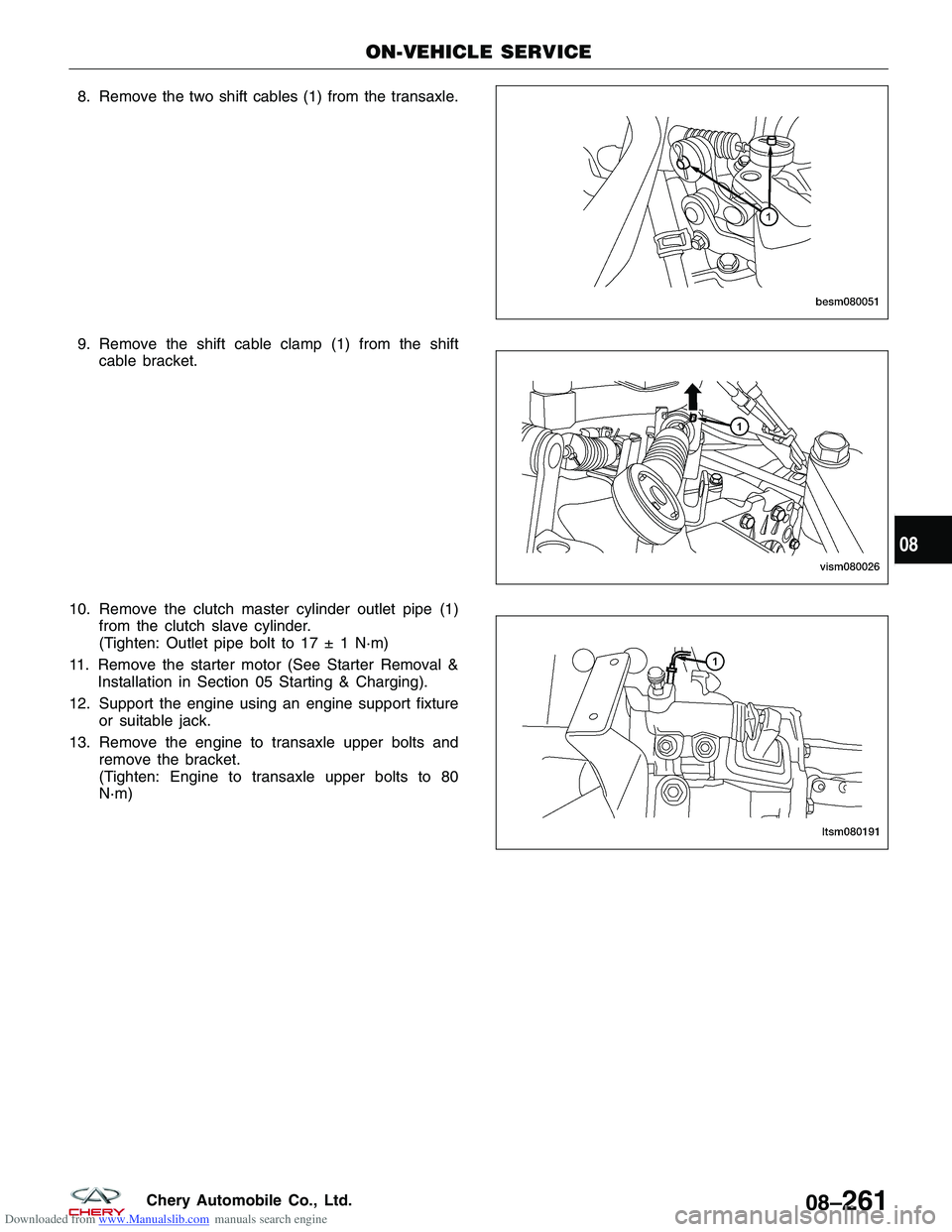
Downloaded from www.Manualslib.com manuals search engine 8. Remove the two shift cables (1) from the transaxle.
9. Remove the shift cable clamp (1) from the shiftcable bracket.
10. Remove the clutch master cylinder outlet pipe (1) from the clutch slave cylinder.
(Tighten: Outlet pipe bolt to 17 ± 1 N·m)
11. Remove the starter motor (See Starter Removal & Installation in Section 05 Starting & Charging).
12. Support the engine using an engine support fixture or suitable jack.
13. Remove the engine to transaxle upper bolts and remove the bracket.
(Tighten: Engine to transaxle upper bolts to 80
N·m)
ON-VEHICLE SERVICE
BESM080051
VISM080026
LTSM080191
08
08–261Chery Automobile Co., Ltd.
Page 1205 of 1903
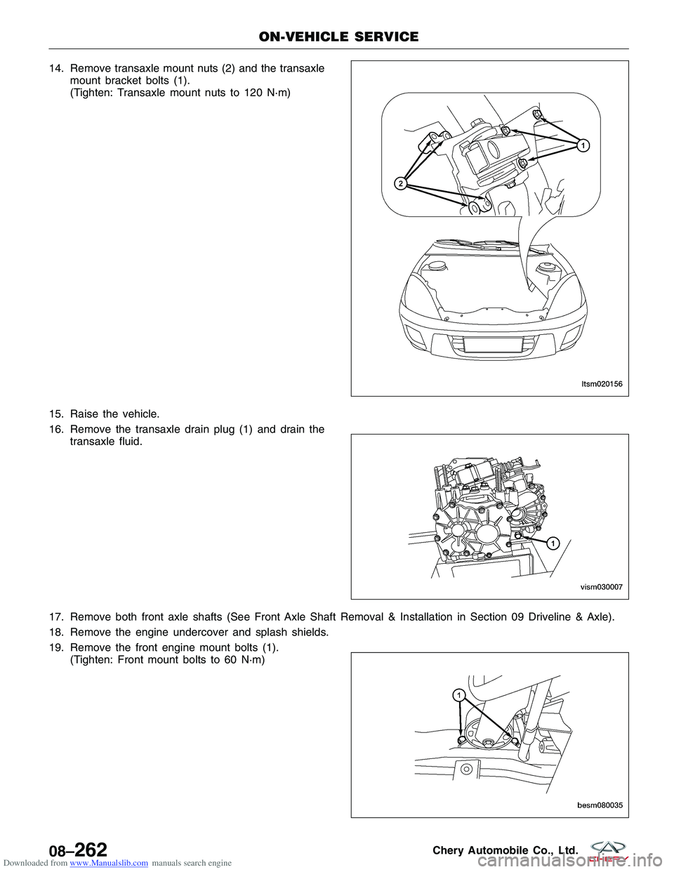
Downloaded from www.Manualslib.com manuals search engine 14. Remove transaxle mount nuts (2) and the transaxlemount bracket bolts (1).
(Tighten: Transaxle mount nuts to 120 N·m)
15. Raise the vehicle.
16. Remove the transaxle drain plug (1) and drain the transaxle fluid.
17. Remove both front axle shafts (See Front Axle Shaft Removal & Installation in Section 09 Driveline & Axle).
18. Remove the engine undercover and splash shields.
19. Remove the front engine mount bolts (1). (Tighten: Front mount bolts to 60 N·m)
ON-VEHICLE SERVICE
LTSM020156
VISM030007
BESM080035
08–262Chery Automobile Co., Ltd.
Page 1206 of 1903
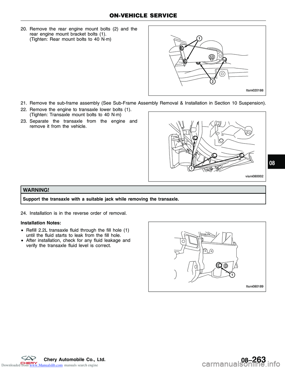
Downloaded from www.Manualslib.com manuals search engine 20. Remove the rear engine mount bolts (2) and therear engine mount bracket bolts (1).
(Tighten: Rear mount bolts to 40 N·m)
21. Remove the sub-frame assembly (See Sub-Frame Assembly Removal & Installation in Section 10 Suspension).
22. Remove the engine to transaxle lower bolts (1). (Tighten: Transaxle mount bolts to 40 N·m)
23. Separate the transaxle from the engine and remove it from the vehicle.
WARNING!
Support the transaxle with a suitable jack while removing the transaxle.
24. Installation is in the reverse order of removal.
Installation Notes:
•Refill 2.2L transaxle fluid through the fill hole (1)
until the fluid starts to leak from the fill hole.
• After installation, check for any fluid leakage and
verify the transaxle fluid level is correct.
ON-VEHICLE SERVICE
LTSM020188
VISM080002
LTSM080189
08
08–263Chery Automobile Co., Ltd.
Page 1207 of 1903
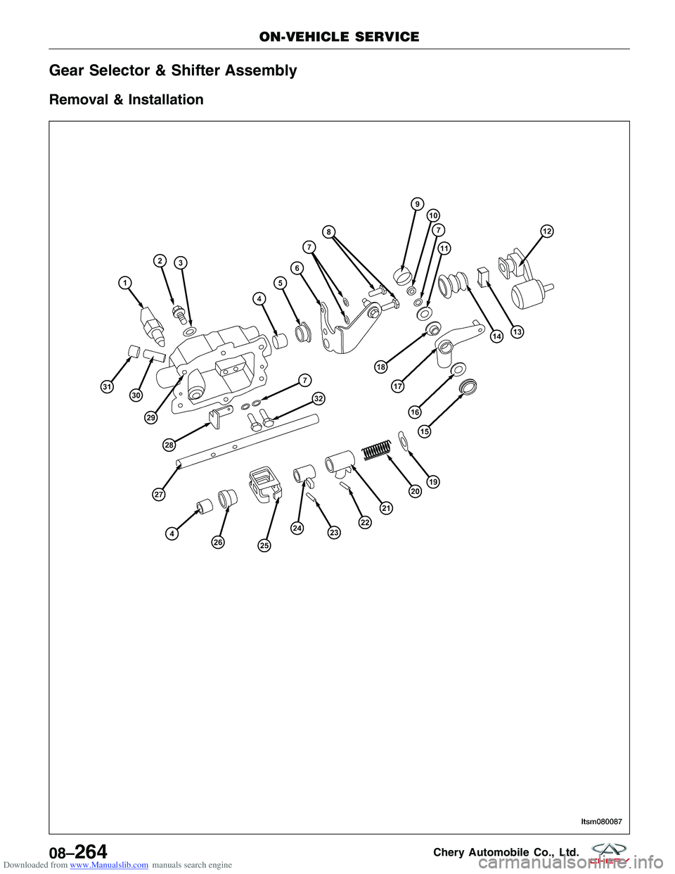
Downloaded from www.Manualslib.com manuals search engine Gear Selector & Shifter Assembly
Removal & Installation
ON-VEHICLE SERVICE
LTSM08008708–264Chery Automobile Co., Ltd.
Page 1208 of 1903
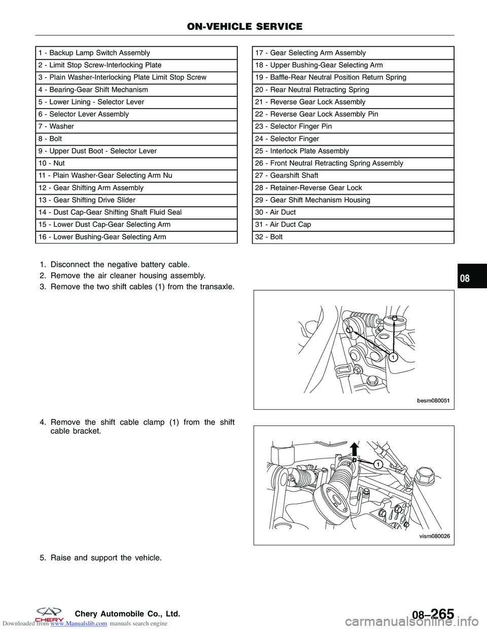
Downloaded from www.Manualslib.com manuals search engine 1. Disconnect the negative battery cable.
2. Remove the air cleaner housing assembly.
3. Remove the two shift cables (1) from the transaxle.
4. Remove the shift cable clamp (1) from the shiftcable bracket.
5. Raise and support the vehicle.
1 - Backup Lamp Switch Assembly
2 - Limit Stop Screw-Interlocking Plate
3 - Plain Washer-Interlocking Plate Limit Stop Screw
4 - Bearing-Gear Shift Mechanism
5 - Lower Lining - Selector Lever
6 - Selector Lever Assembly
7 - Washer
8 - Bolt
9 - Upper Dust Boot - Selector Lever
10 - Nut
11 - Plain Washer-Gear Selecting Arm Nu
12 - Gear Shifting Arm Assembly
13 - Gear Shifting Drive Slider
14 - Dust Cap-Gear Shifting Shaft Fluid Seal
15 - Lower Dust Cap-Gear Selecting Arm
16 - Lower Bushing-Gear Selecting Arm17 - Gear Selecting Arm Assembly
18 - Upper Bushing-Gear Selecting Arm
19 - Baffle-Rear Neutral Position Return Spring
20 - Rear Neutral Retracting Spring
21 - Reverse Gear Lock Assembly
22 - Reverse Gear Lock Assembly Pin
23 - Selector Finger Pin
24 - Selector Finger
25 - Interlock Plate Assembly
26 - Front Neutral Retracting Spring Assembly
27 - Gearshift Shaft
28 - Retainer-Reverse Gear Lock
29 - Gear Shift Mechanism Housing
30 - Air Duct
31 - Air Duct Cap
32 - Bolt
ON-VEHICLE SERVICE
LTSM080087
BESM080051 VISM080026
08
08–265Chery Automobile Co., Ltd.
Page 1209 of 1903
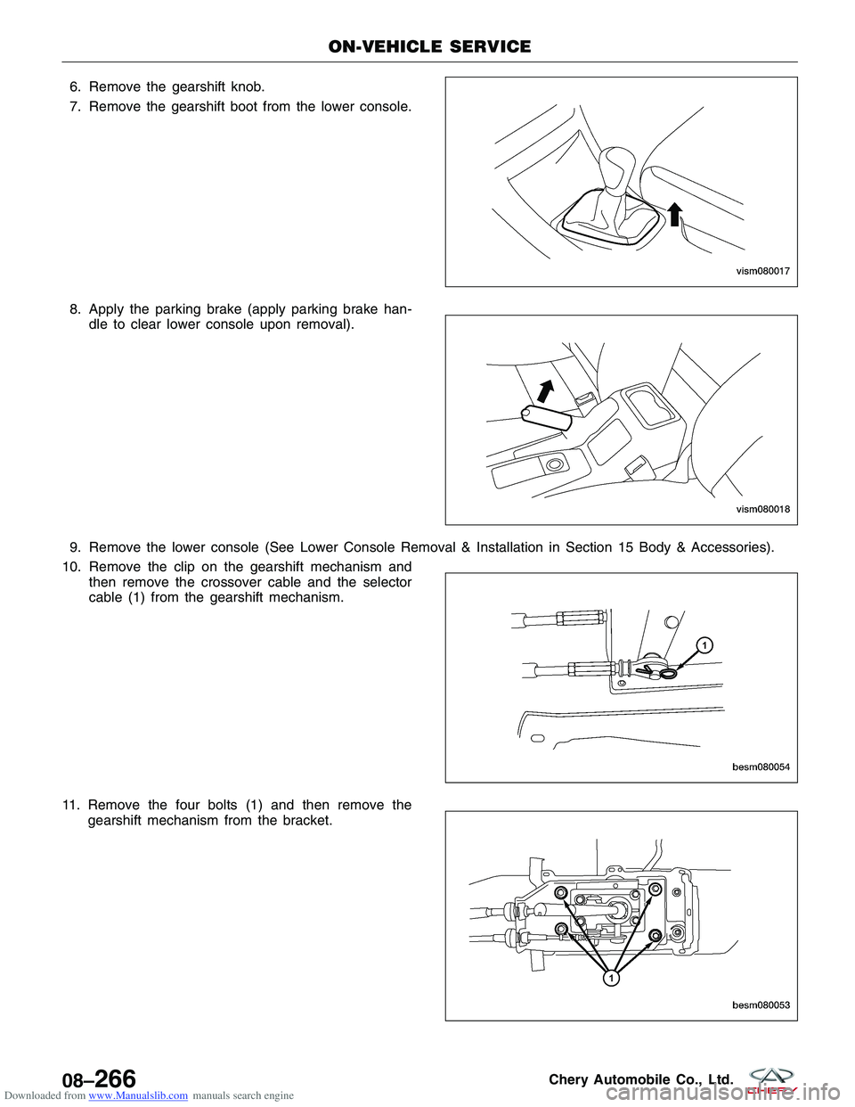
Downloaded from www.Manualslib.com manuals search engine 6. Remove the gearshift knob.
7. Remove the gearshift boot from the lower console.
8. Apply the parking brake (apply parking brake han-dle to clear lower console upon removal).
9. Remove the lower console (See Lower Console Removal & Installation in Section 15 Body & Accessories).
10. Remove the clip on the gearshift mechanism and then remove the crossover cable and the selector
cable (1) from the gearshift mechanism.
11. Remove the four bolts (1) and then remove the gearshift mechanism from the bracket.
ON-VEHICLE SERVICE
VISM080017
VISM080018
BESM080054
BESM080053
08–266Chery Automobile Co., Ltd.
Page 1210 of 1903
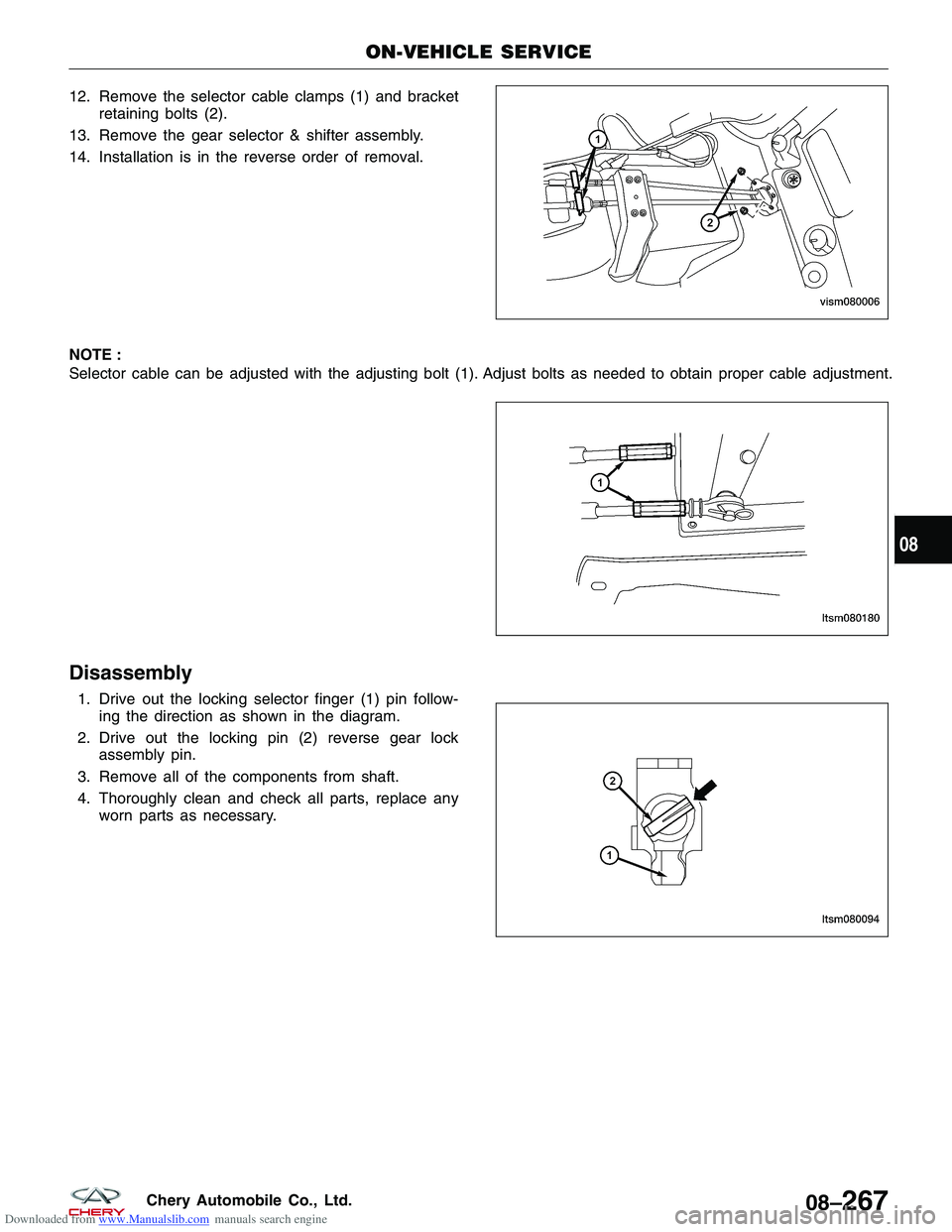
Downloaded from www.Manualslib.com manuals search engine 12. Remove the selector cable clamps (1) and bracketretaining bolts (2).
13. Remove the gear selector & shifter assembly.
14. Installation is in the reverse order of removal.
NOTE :
Selector cable can be adjusted with the adjusting bolt (1). Adjust bolts as needed to obtain proper cable adjustment.
Disassembly
1. Drive out the locking selector finger (1) pin follow- ing the direction as shown in the diagram.
2. Drive out the locking pin (2) reverse gear lock assembly pin.
3. Remove all of the components from shaft.
4. Thoroughly clean and check all parts, replace any worn parts as necessary.
ON-VEHICLE SERVICE
VISM080006
LTSM080180
LTSM080094
08
08–267Chery Automobile Co., Ltd.