CHERY TIGGO 2009 Service Repair Manual
Manufacturer: CHERY, Model Year: 2009,
Model line: TIGGO,
Model: CHERY TIGGO 2009
Pages: 1903, PDF Size: 33.38 MB
CHERY TIGGO 2009 Service Repair Manual
TIGGO 2009
CHERY
CHERY
https://www.carmanualsonline.info/img/53/56852/w960_56852-0.png
CHERY TIGGO 2009 Service Repair Manual
Trending: warning light, oil change, ELECTRONIC CONTROLS, oil level, weight, odometer, change time
Page 1231 of 1903
Downloaded from www.Manualslib.com manuals search engine NOTE :
The following special tools are required to perform the repair procedure:
•MB-998801 - Bearing Remover
• MB-998812 - Installer Cap
• MB-998814 - Installer Connector (200 mm)
• MB-998813 - Installer (100)
• MB-998818 - Installer Connector (38 mm)
• MB-998819 - Installer Connector (40 mm)
• MB-998822 - Installer Connector (46 mm)
• MB-998825 - Installer Connector (52 mm)
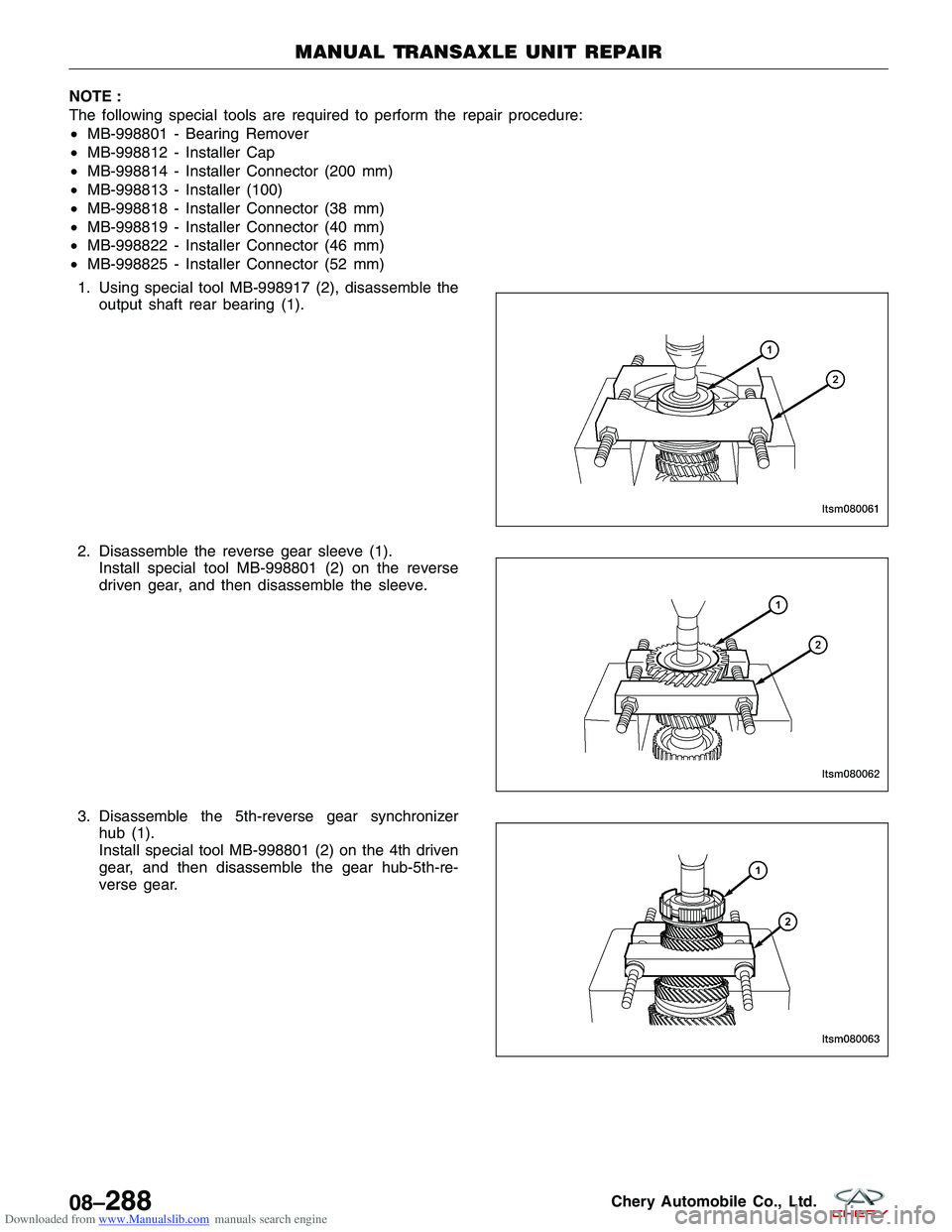
1. Using special tool MB-998917 (2), disassemble the output shaft rear bearing (1).
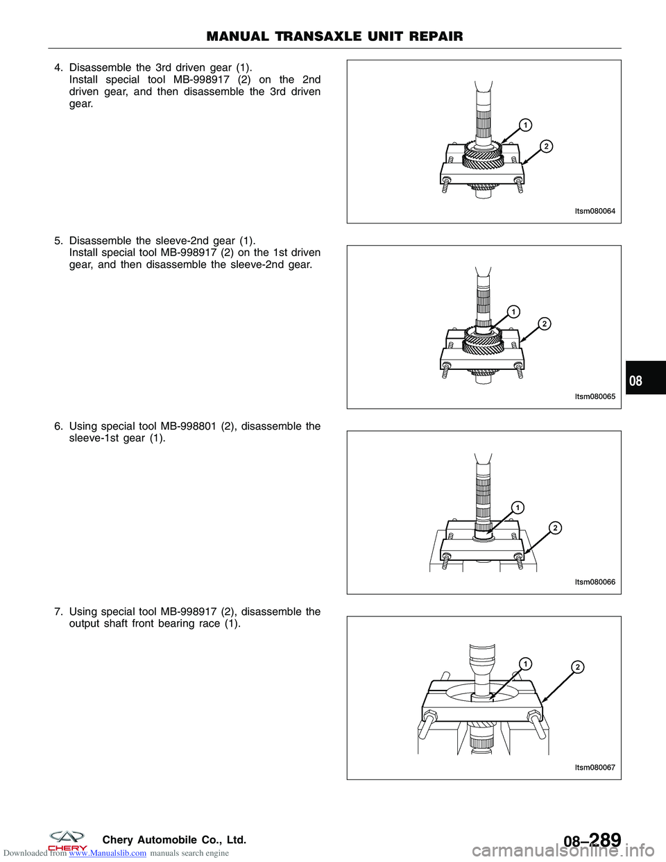
2. Disassemble the reverse gear sleeve (1). Install special tool MB-998801 (2) on the reverse
driven gear, and then disassemble the sleeve.
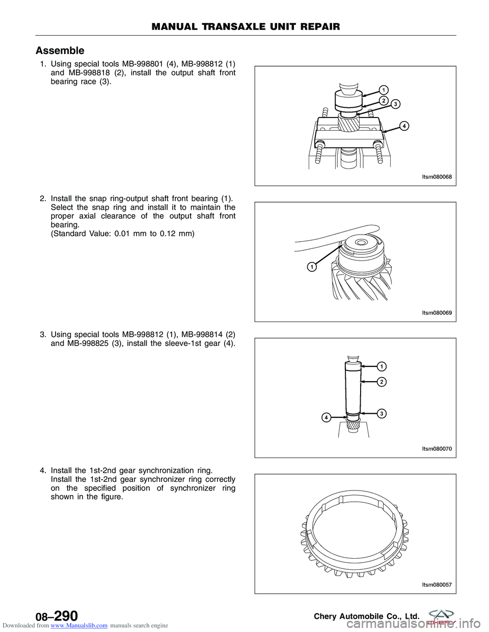
3. Disassemble the 5th-reverse gear synchronizer hub (1).
Install special tool MB-998801 (2) on the 4th driven
gear, and then disassemble the gear hub-5th-re-
verse gear.
MANUAL TRANSAXLE UNIT REPAIR
LTSM080061
LTSM080062
LTSM080063
08–288Chery Automobile Co., Ltd.
Page 1232 of 1903
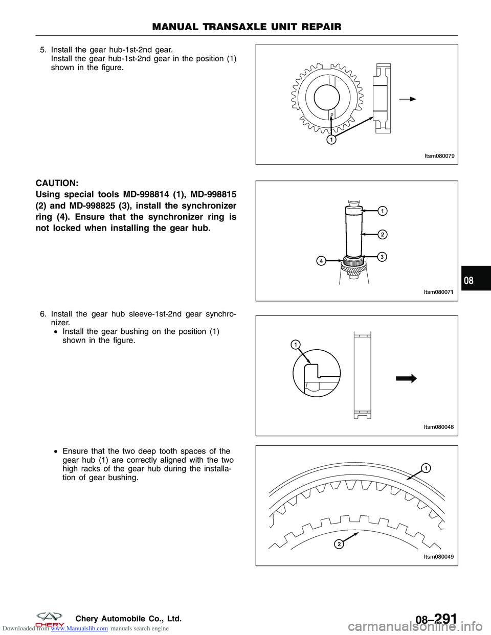
Downloaded from www.Manualslib.com manuals search engine 4. Disassemble the 3rd driven gear (1).Install special tool MB-998917 (2) on the 2nd
driven gear, and then disassemble the 3rd driven
gear.
5. Disassemble the sleeve-2nd gear (1). Install special tool MB-998917 (2) on the 1st driven
gear, and then disassemble the sleeve-2nd gear.
6. Using special tool MB-998801 (2), disassemble the sleeve-1st gear (1).
7. Using special tool MB-998917 (2), disassemble the output shaft front bearing race (1).
MANUAL TRANSAXLE UNIT REPAIR
LTSM080064
LTSM080065
LTSM080066
LTSM080067
08
08–289Chery Automobile Co., Ltd.
Page 1233 of 1903
Downloaded from www.Manualslib.com manuals search engine Assemble
1. Using special tools MB-998801 (4), MB-998812 (1)and MB-998818 (2), install the output shaft front
bearing race (3).
2. Install the snap ring-output shaft front bearing (1). Select the snap ring and install it to maintain the
proper axial clearance of the output shaft front
bearing.
(Standard Value: 0.01 mm to 0.12 mm)
3. Using special tools MB-998812 (1), MB-998814 (2) and MB-998825 (3), install the sleeve-1st gear (4).
4. Install the 1st-2nd gear synchronization ring. Install the 1st-2nd gear synchronizer ring correctly
on the specified position of synchronizer ring
shown in the figure.
MANUAL TRANSAXLE UNIT REPAIR
LTSM080068
LTSM080069
LTSM080070
LTSM080057
08–290Chery Automobile Co., Ltd.
Page 1234 of 1903
Downloaded from www.Manualslib.com manuals search engine 5. Install the gear hub-1st-2nd gear.Install the gear hub-1st-2nd gear in the position (1)
shown in the figure.
CAUTION:
Using special tools MD-998814 (1), MD-998815
(2) and MD-998825 (3), install the synchronizer
ring (4). Ensure that the synchronizer ring is
not locked when installing the gear hub.
6. Install the gear hub sleeve-1st-2nd gear synchro-nizer.• Install the gear bushing on the position (1)
shown in the figure.
• Ensure that the two deep tooth spaces of the
gear hub (1) are correctly aligned with the two
high racks of the gear hub during the installa-
tion of gear bushing.
MANUAL TRANSAXLE UNIT REPAIR
LTSM080079
LTSM080071
LTSM080048
LTSM080049
08
08–291Chery Automobile Co., Ltd.
Page 1235 of 1903
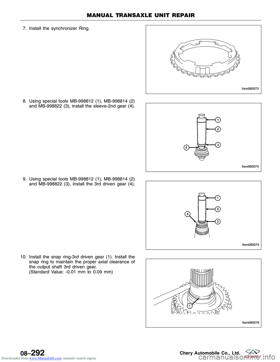
Downloaded from www.Manualslib.com manuals search engine 7. Install the synchronizer Ring.
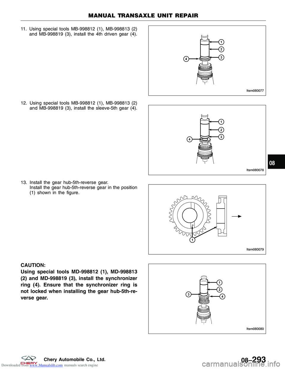
8. Using special tools MB-998812 (1), MB-998814 (2)and MB-998822 (3), install the sleeve-2nd gear (4).
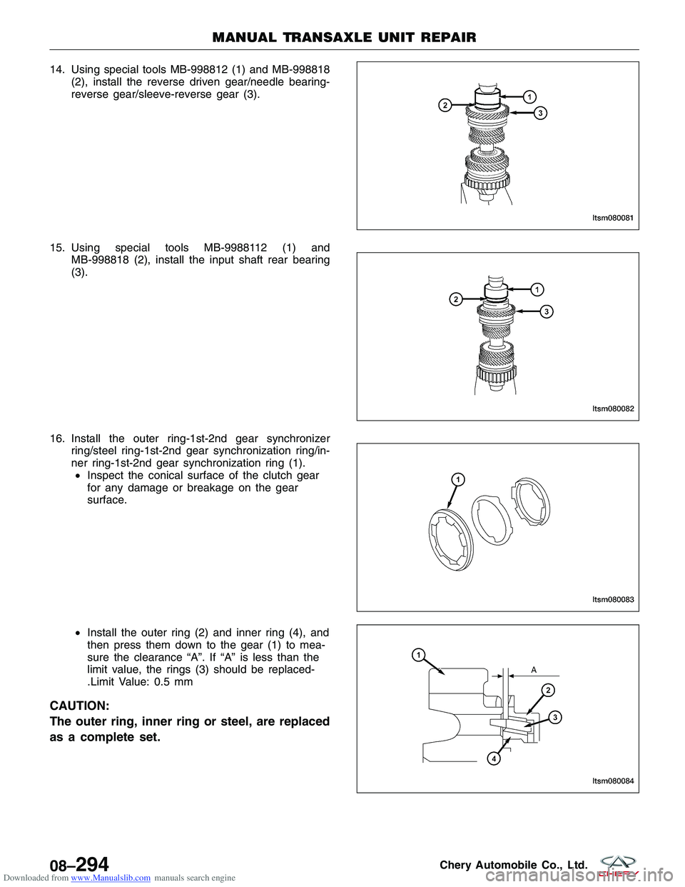
9. Using special tools MB-998812 (1), MB-998814 (2) and MB-998822 (3), install the 3rd driven gear (4).
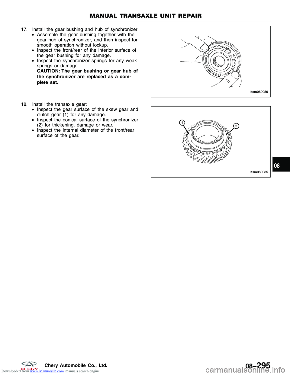
10. Install the snap ring-3rd driven gear (1). Install the snap ring to maintain the proper axial clearance of
the output shaft 3rd driven gear.
(Standard Value: -0.01 mm to 0.09 mm)
MANUAL TRANSAXLE UNIT REPAIR
LTSM080073
LTSM080074
LTSM080075
LTSM080076
08–292Chery Automobile Co., Ltd.
Page 1236 of 1903
Downloaded from www.Manualslib.com manuals search engine 11. Using special tools MB-998812 (1), MB-998813 (2)and MB-998819 (3), install the 4th driven gear (4).
12. Using special tools MB-998812 (1), MB-998813 (2) and MB-998819 (3), install the sleeve-5th gear (4).
13. Install the gear hub-5th-reverse gear. Install the gear hub-5th-reverse gear in the position
(1) shown in the figure.
CAUTION:
Using special tools MD-998812 (1), MD-998813
(2) and MD-998819 (3), install the synchronizer
ring (4). Ensure that the synchronizer ring is
not locked when installing the gear hub-5th-re-
verse gear.
MANUAL TRANSAXLE UNIT REPAIR
LTSM080077
LTSM080078
LTSM080079
LTSM080080
08
08–293Chery Automobile Co., Ltd.
Page 1237 of 1903
Downloaded from www.Manualslib.com manuals search engine 14. Using special tools MB-998812 (1) and MB-998818(2), install the reverse driven gear/needle bearing-
reverse gear/sleeve-reverse gear (3).
15. Using special tools MB-9988112 (1) and MB-998818 (2), install the input shaft rear bearing
(3).
16. Install the outer ring-1st-2nd gear synchronizer ring/steel ring-1st-2nd gear synchronization ring/in-
ner ring-1st-2nd gear synchronization ring (1).• Inspect the conical surface of the clutch gear
for any damage or breakage on the gear
surface.
• Install the outer ring (2) and inner ring (4), and
then press them down to the gear (1) to mea-
sure the clearance “A”. If “A” is less than the
limit value, the rings (3) should be replaced-
.Limit Value: 0.5 mm
CAUTION:
The outer ring, inner ring or steel, are replaced
as a complete set.
MANUAL TRANSAXLE UNIT REPAIR
LTSM080081
LTSM080082
LTSM080083
LTSM080084
08–294Chery Automobile Co., Ltd.
Page 1238 of 1903
Downloaded from www.Manualslib.com manuals search engine 17. Install the gear bushing and hub of synchronizer:•Assemble the gear bushing together with the
gear hub of synchronizer, and then inspect for
smooth operation without lockup.
• Inspect the front/rear of the interior surface of
the gear bushing for any damage.
• Inspect the synchronizer springs for any weak
springs or damage.
CAUTION: The gear bushing or gear hub of
the synchronizer are replaced as a com-
plete set.
18. Install the transaxle gear: •Inspect the gear surface of the skew gear and
clutch gear (1) for any damage.
• Inspect the conical surface of the synchronizer
(2) for thickening, damage or wear.
• Inspect the internal diameter of the front/rear
surface of the gear.
MANUAL TRANSAXLE UNIT REPAIR
LTSM080059
LTSM080085
08
08–295Chery Automobile Co., Ltd.
Page 1239 of 1903
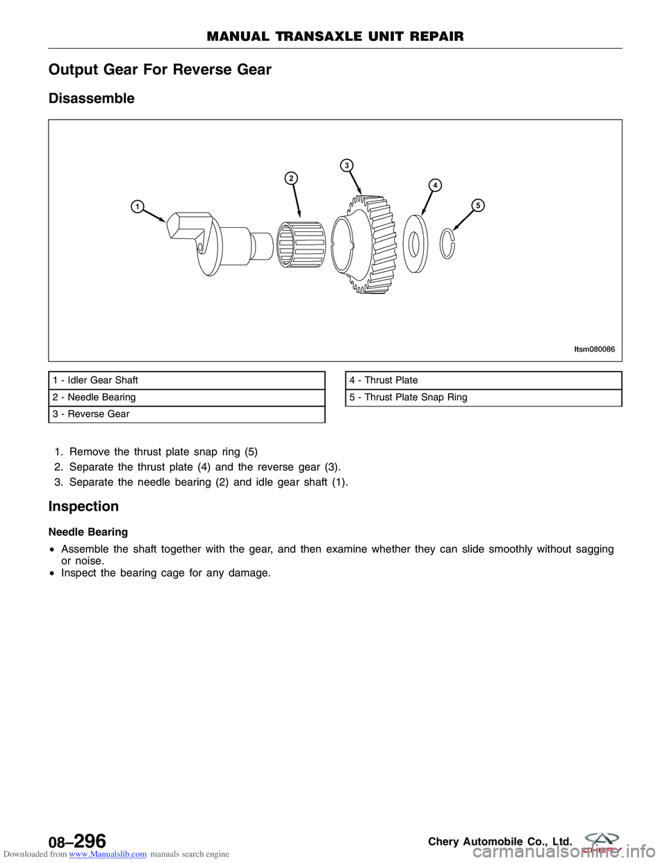
Downloaded from www.Manualslib.com manuals search engine Output Gear For Reverse Gear
Disassemble
1. Remove the thrust plate snap ring (5)
2. Separate the thrust plate (4) and the reverse gear (3).
3. Separate the needle bearing (2) and idle gear shaft (1).
Inspection
Needle Bearing
•Assemble the shaft together with the gear, and then examine whether they can slide smoothly without sagging
or noise.
• Inspect the bearing cage for any damage.
1 - Idler Gear Shaft
2 - Needle Bearing
3 - Reverse Gear4 - Thrust Plate
5 - Thrust Plate Snap Ring
MANUAL TRANSAXLE UNIT REPAIR
LTSM080086
08–296Chery Automobile Co., Ltd.
Page 1240 of 1903
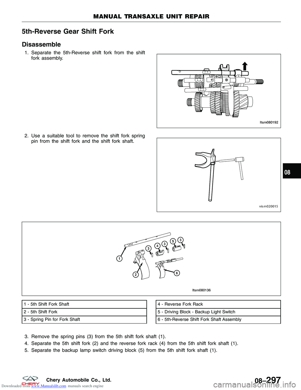
Downloaded from www.Manualslib.com manuals search engine 5th-Reverse Gear Shift Fork
Disassemble
1. Separate the 5th-Reverse shift fork from the shiftfork assembly.
2. Use a suitable tool to remove the shift fork spring pin from the shift fork and the shift fork shaft.
3. Remove the spring pins (3) from the 5th shift fork shaft (1).
4. Separate the 5th shift fork (2) and the reverse fork rack (4) from the 5th shift fork shaft (1).
5. Separate the backup lamp switch driving block (5) from the 5th shift fork shaft (1).
1 - 5th Shift Fork Shaft
2 - 5th Shift Fork
3 - Spring Pin for Fork Shaft4 - Reverse Fork Rack
5 - Driving Block - Backup Light Switch
6 - 5th-Reverse Shift Fork Shaft Assembly
MANUAL TRANSAXLE UNIT REPAIR
LTSM080192 VISM020015
LTSM080136
08
08–297Chery Automobile Co., Ltd.
Trending: spare tire location, oil dipstick, engine, center console, remote control, heater, reset
