CHERY TIGGO 2009 Service Repair Manual
Manufacturer: CHERY, Model Year: 2009,
Model line: TIGGO,
Model: CHERY TIGGO 2009
Pages: 1903, PDF Size: 33.38 MB
CHERY TIGGO 2009 Service Repair Manual
TIGGO 2009
CHERY
CHERY
https://www.carmanualsonline.info/img/53/56852/w960_56852-0.png
CHERY TIGGO 2009 Service Repair Manual
Trending: ESP, service indicator, coolant temperature, jump start, air conditioning, fuse box, selector sensor
Page 1431 of 1903
Downloaded from www.Manualslib.com manuals search engine Operation
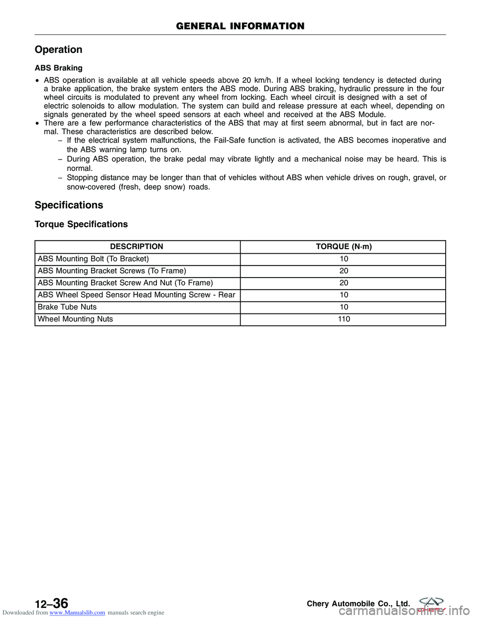
ABS Braking
•ABS operation is available at all vehicle speeds above 20 km/h. If a wheel locking tendency is detected during
a brake application, the brake system enters the ABS mode. During ABS braking, hydraulic pressure in the four
wheel circuits is modulated to prevent any wheel from locking. Each wheel circuit is designed with a set of
electric solenoids to allow modulation. The system can build and release pressure at each wheel, depending on
signals generated by the wheel speed sensors at each wheel and received at the ABS Module.
• There are a few performance characteristics of the ABS that may at first seem abnormal, but in fact are nor-
mal. These characteristics are described below.
� If the electrical system malfunctions, the Fail-Safe function is activated, the ABS becomes inoperative and
the ABS warning lamp turns on.
� During ABS operation, the brake pedal may vibrate lightly and a mechanical noise may be heard. This is normal.
� Stopping distance may be longer than that of vehicles without ABS when vehicle drives on rough, gravel, or snow-covered (fresh, deep snow) roads.
Specifications
Torque Specifications
DESCRIPTION TORQUE (N·m)
ABS Mounting Bolt (To Bracket) 10
ABS Mounting Bracket Screws (To Frame) 20
ABS Mounting Bracket Screw And Nut (To Frame) 20
ABS Wheel Speed Sensor Head Mounting Screw - Rear 10
Brake Tube Nuts 10
Wheel Mounting Nuts 110
GENERAL INFORMATION
12–36Chery Automobile Co., Ltd.
Page 1432 of 1903
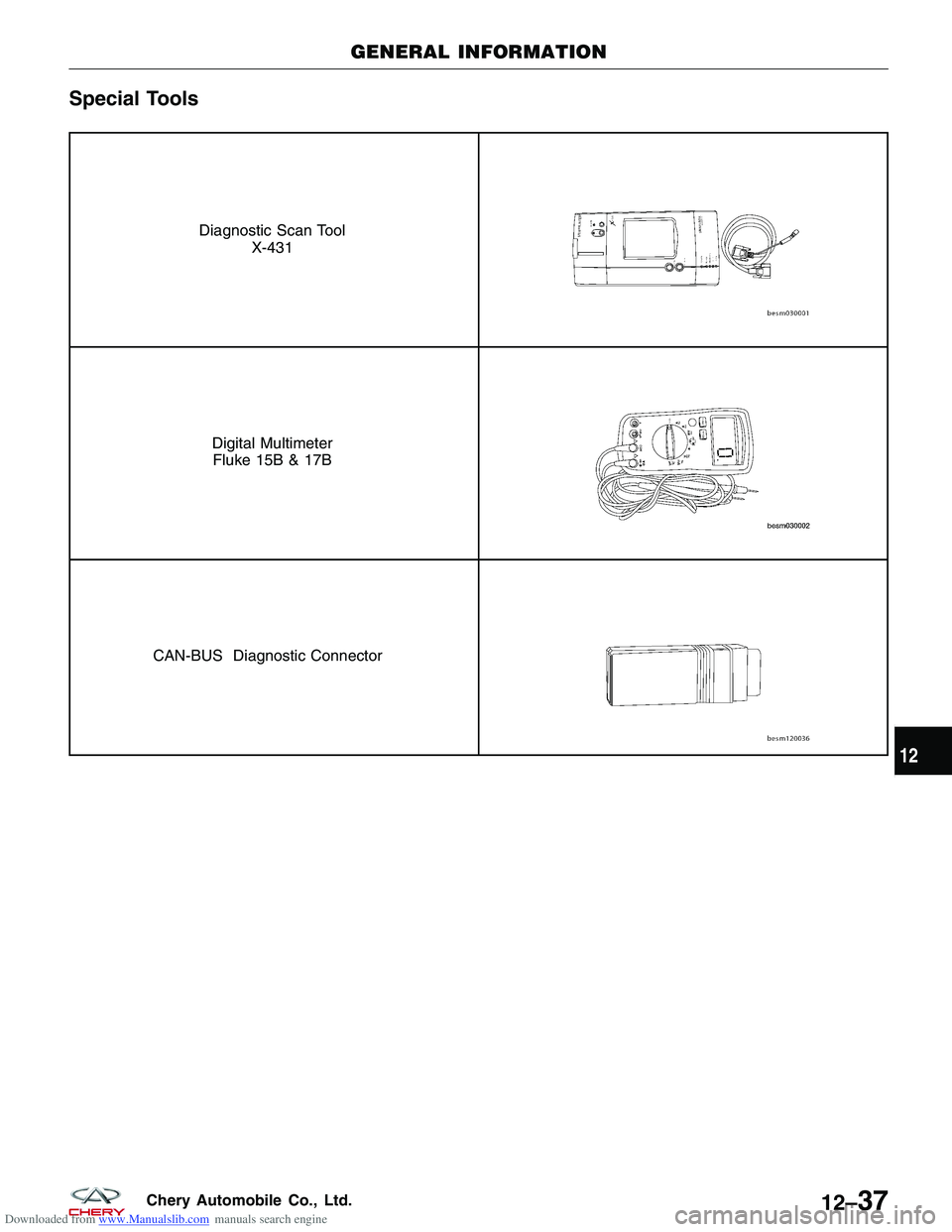
Downloaded from www.Manualslib.com manuals search engine Special Tools
Diagnostic Scan ToolX-431
Digital MultimeterFluke 15B & 17B
CAN-BUS Diagnostic Connector
GENERAL INFORMATION
12
12–37Chery Automobile Co., Ltd.
Page 1433 of 1903
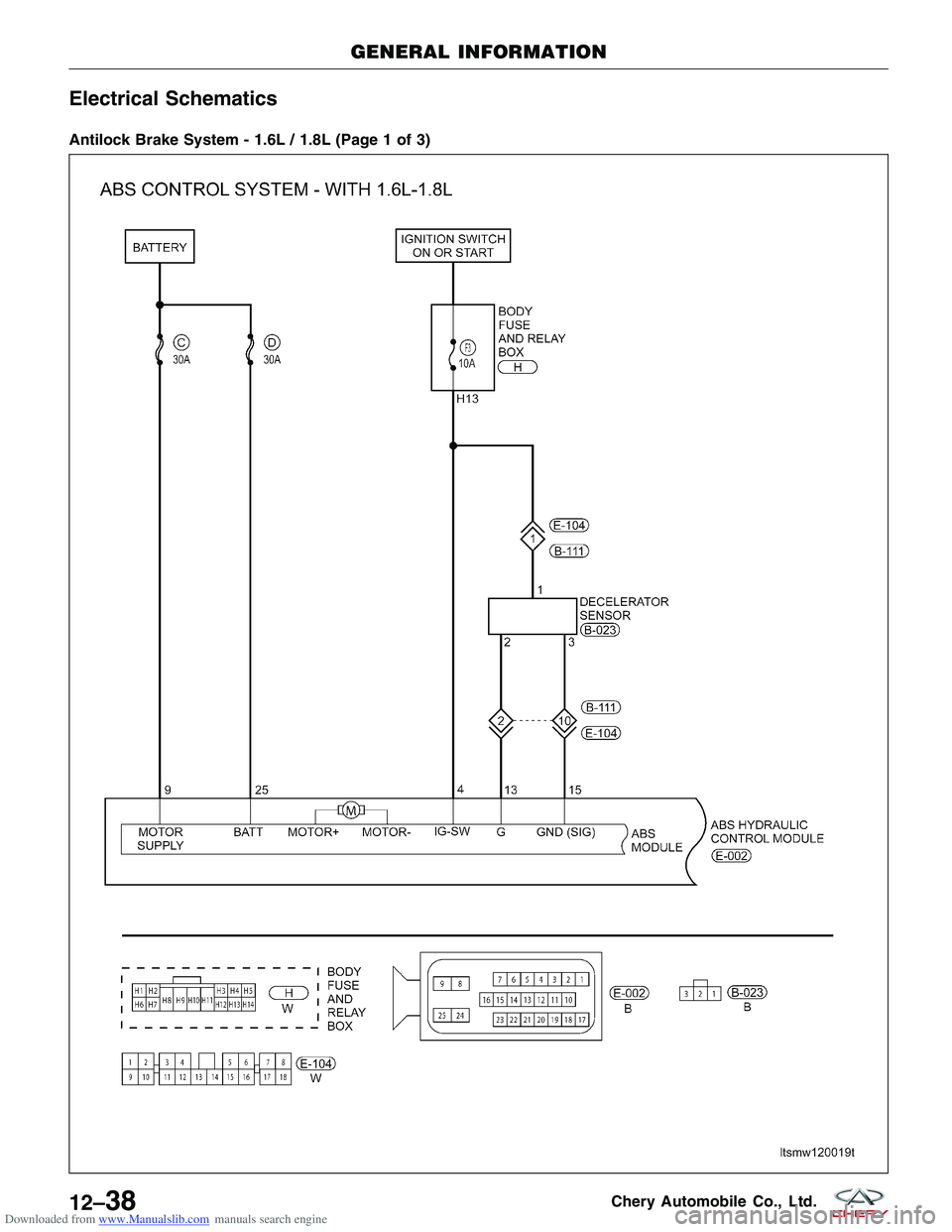
Downloaded from www.Manualslib.com manuals search engine Electrical Schematics
Antilock Brake System - 1.6L / 1.8L (Page 1 of 3)
GENERAL INFORMATION
LTSMW120019T
12–38Chery Automobile Co., Ltd.
Page 1434 of 1903
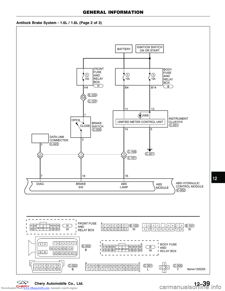
Downloaded from www.Manualslib.com manuals search engine Antilock Brake System - 1.6L / 1.8L (Page 2 of 3)
GENERAL INFORMATION
LTSMW120020T
12
12–39Chery Automobile Co., Ltd.
Page 1435 of 1903
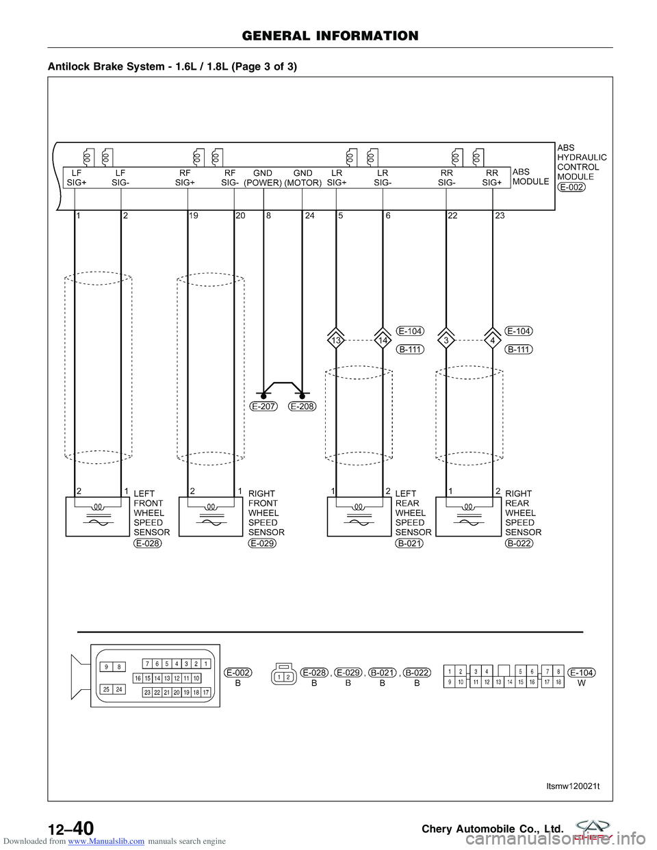
Downloaded from www.Manualslib.com manuals search engine Antilock Brake System - 1.6L / 1.8L (Page 3 of 3)
GENERAL INFORMATION
LTSMW120021T
12–40Chery Automobile Co., Ltd.
Page 1436 of 1903
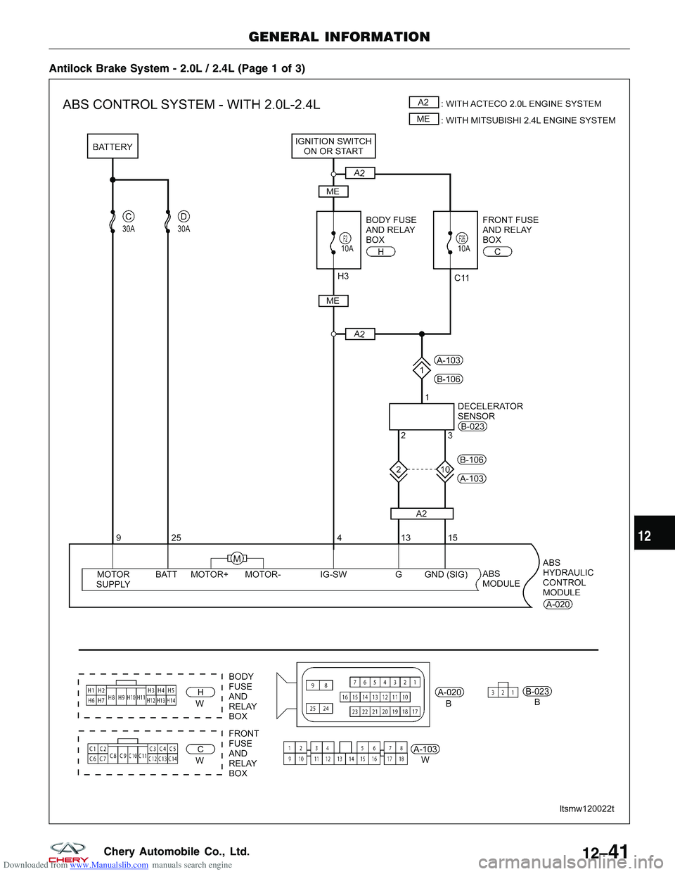
Downloaded from www.Manualslib.com manuals search engine Antilock Brake System - 2.0L / 2.4L (Page 1 of 3)
GENERAL INFORMATION
LTSMW120022T
12
12–41Chery Automobile Co., Ltd.
Page 1437 of 1903
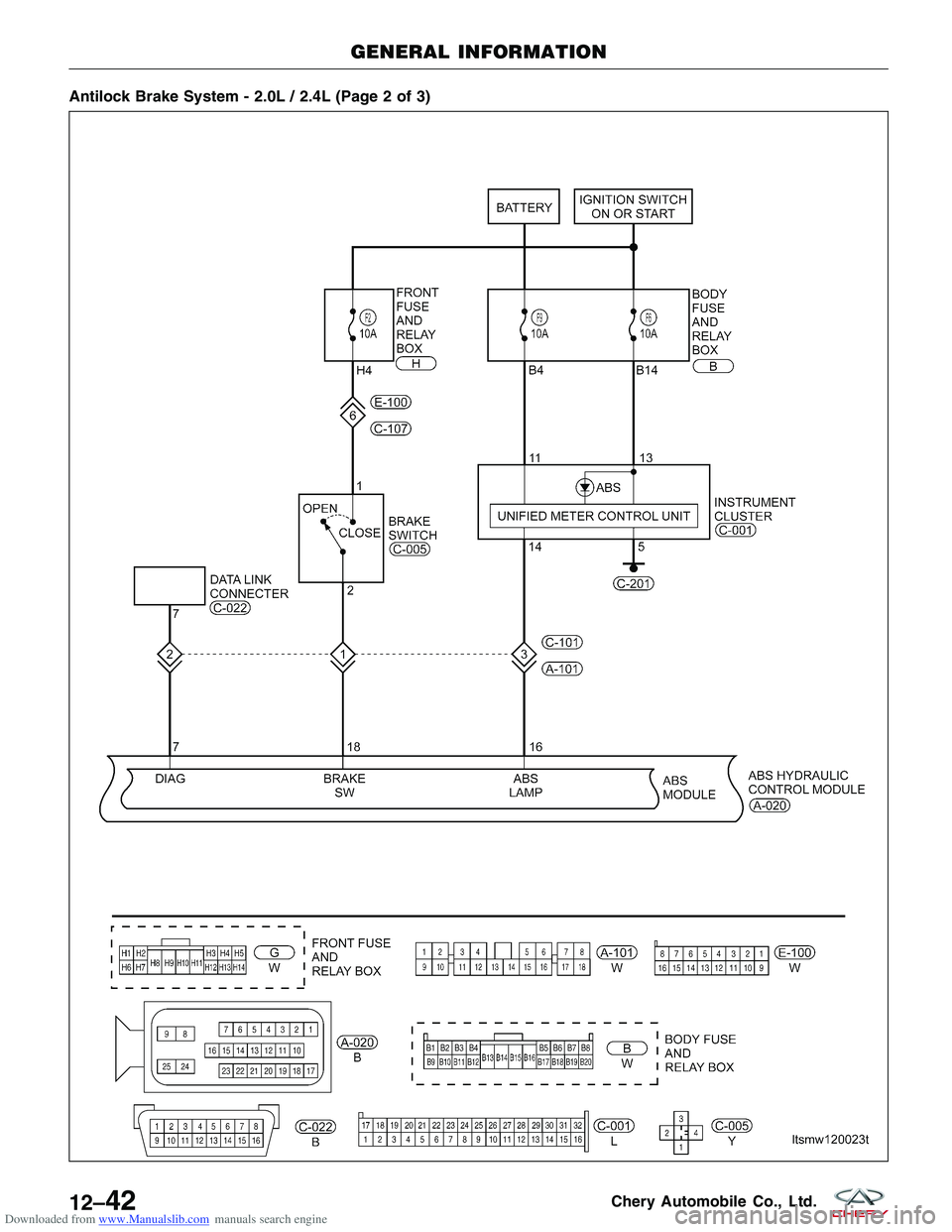
Downloaded from www.Manualslib.com manuals search engine Antilock Brake System - 2.0L / 2.4L (Page 2 of 3)
GENERAL INFORMATION
LTSMW120023T
12–42Chery Automobile Co., Ltd.
Page 1438 of 1903
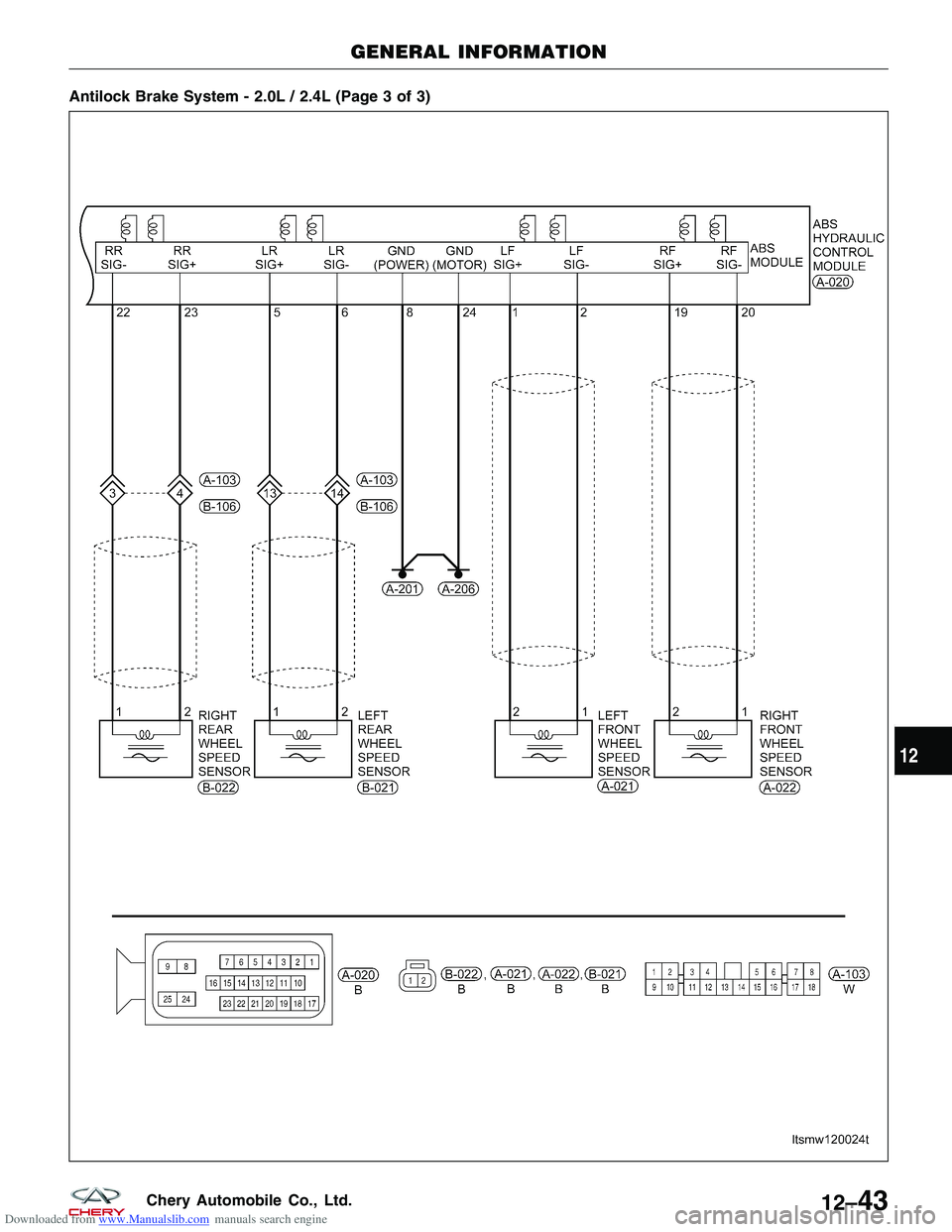
Downloaded from www.Manualslib.com manuals search engine Antilock Brake System - 2.0L / 2.4L (Page 3 of 3)
GENERAL INFORMATION
LTSMW120024T
12
12–43Chery Automobile Co., Ltd.
Page 1439 of 1903
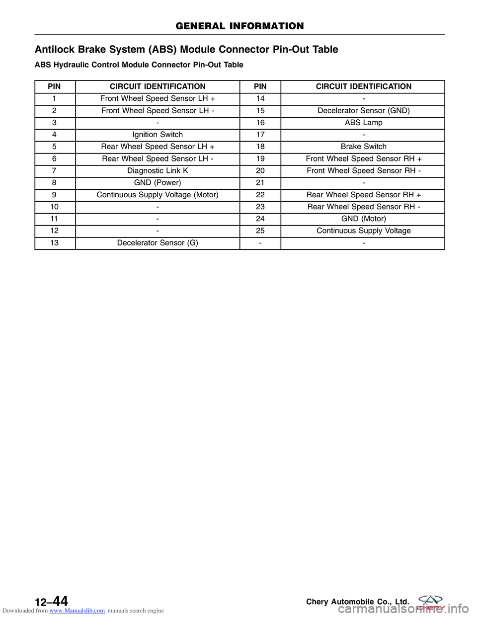
Downloaded from www.Manualslib.com manuals search engine Antilock Brake System (ABS) Module Connector Pin-Out Table
ABS Hydraulic Control Module Connector Pin-Out Table
PINCIRCUIT IDENTIFICATION PINCIRCUIT IDENTIFICATION
1 Front Wheel Speed Sensor LH + 14-
2 Front Wheel Speed Sensor LH - 15Decelerator Sensor (GND)
3 -16ABS Lamp
4 Ignition Switch 17-
5 Rear Wheel Speed Sensor LH + 18Brake Switch
6 Rear Wheel Speed Sensor LH - 19Front Wheel Speed Sensor RH +
7 Diagnostic Link K 20Front Wheel Speed Sensor RH -
8 GND (Power) 21-
9 Continuous Supply Voltage (Motor) 22 Rear Wheel Speed Sensor RH +
10 -23Rear Wheel Speed Sensor RH -
11 -24GND (Motor)
12 -25Continuous Supply Voltage
13 Decelerator Sensor (G) --
GENERAL INFORMATION
12–44Chery Automobile Co., Ltd.
Page 1440 of 1903
Downloaded from www.Manualslib.com manuals search engine DIAGNOSIS & TESTING
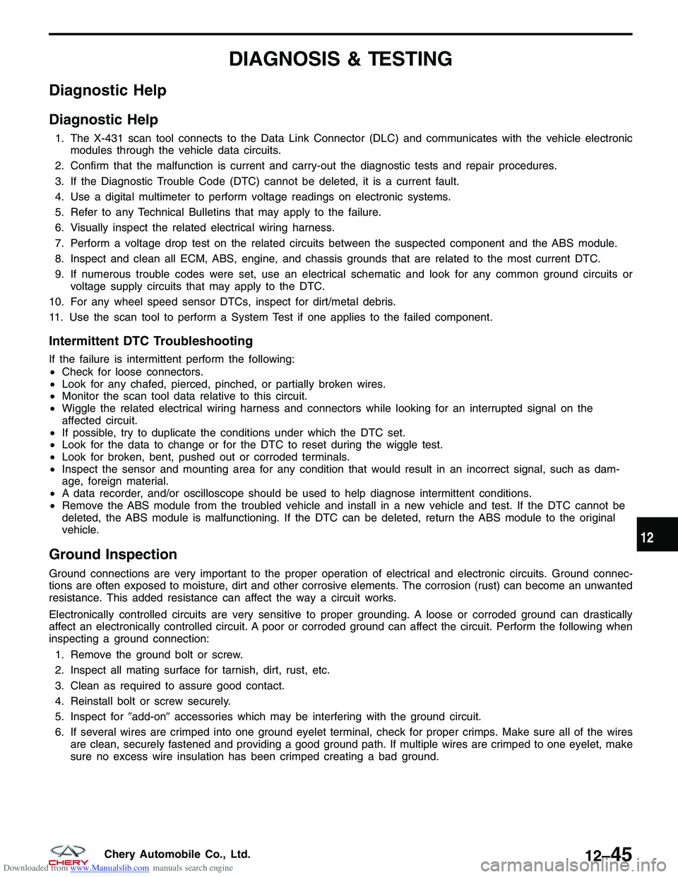
Diagnostic Help
Diagnostic Help
1. The X-431 scan tool connects to the Data Link Connector (DLC) and communicates with the vehicle electronicmodules through the vehicle data circuits.
2. Confirm that the malfunction is current and carry-out the diagnostic tests and repair procedures.
3. If the Diagnostic Trouble Code (DTC) cannot be deleted, it is a current fault.
4. Use a digital multimeter to perform voltage readings on electronic systems.
5. Refer to any Technical Bulletins that may apply to the failure.
6. Visually inspect the related electrical wiring harness.
7. Perform a voltage drop test on the related circuits between the suspected component and the ABS module.
8. Inspect and clean all ECM, ABS, engine, and chassis grounds that are related to the most current DTC.
9. If numerous trouble codes were set, use an electrical schematic and look for any common ground circuits or voltage supply circuits that may apply to the DTC.
10. For any wheel speed sensor DTCs, inspect for dirt/metal debris.
11. Use the scan tool to perform a System Test if one applies to the failed component.
Intermittent DTC Troubleshooting
If the failure is intermittent perform the following:
• Check for loose connectors.
• Look for any chafed, pierced, pinched, or partially broken wires.
• Monitor the scan tool data relative to this circuit.
• Wiggle the related electrical wiring harness and connectors while looking for an interrupted signal on the
affected circuit.
• If possible, try to duplicate the conditions under which the DTC set.
• Look for the data to change or for the DTC to reset during the wiggle test.
• Look for broken, bent, pushed out or corroded terminals.
• Inspect the sensor and mounting area for any condition that would result in an incorrect signal, such as dam-
age, foreign material.
• A data recorder, and/or oscilloscope should be used to help diagnose intermittent conditions.
• Remove the ABS module from the troubled vehicle and install in a new vehicle and test. If the DTC cannot be
deleted, the ABS module is malfunctioning. If the DTC can be deleted, return the ABS module to the original
vehicle.
Ground Inspection
Ground connections are very important to the proper operation of electrical and electronic circuits. Ground connec-
tions are often exposed to moisture, dirt and other corrosive elements. The corrosion (rust) can become an unwanted
resistance. This added resistance can affect the way a circuit works.
Electronically controlled circuits are very sensitive to proper grounding. A loose or corroded ground can drastically
affect an electronically controlled circuit. A poor or corroded ground can affect the circuit. Perform the following when
inspecting a ground connection:
1. Remove the ground bolt or screw.
2. Inspect all mating surface for tarnish, dirt, rust, etc.
3. Clean as required to assure good contact.
4. Reinstall bolt or screw securely.
5. Inspect for �add-on�accessories which may be interfering with the ground circuit.
6. If several wires are crimped into one ground eyelet terminal, check for proper crimps. Make sure all of the wires are clean, securely fastened and providing a good ground path. If multiple wires are crimped to one eyelet, make
sure no excess wire insulation has been crimped creating a bad ground.
12
12–45Chery Automobile Co., Ltd.
Trending: tires, roof rack, oil capacity, Jumper, spare tire, power steering, climate control

