CHERY TIGGO 2009 Service Repair Manual
Manufacturer: CHERY, Model Year: 2009,
Model line: TIGGO,
Model: CHERY TIGGO 2009
Pages: 1903, PDF Size: 33.38 MB
CHERY TIGGO 2009 Service Repair Manual
TIGGO 2009
CHERY
CHERY
https://www.carmanualsonline.info/img/53/56852/w960_56852-0.png
CHERY TIGGO 2009 Service Repair Manual
Trending: Roof power, low beam, brakes, C1275, set clock, coolant reservoir, spare wheel
Page 1481 of 1903
Downloaded from www.Manualslib.com manuals search engine Parking Brake Shoes
Removal & Installation
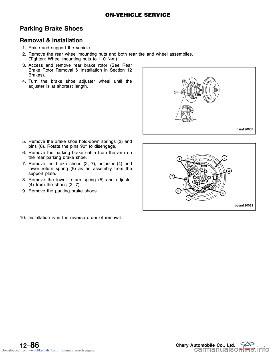
1. Raise and support the vehicle.
2. Remove the rear wheel mounting nuts and both rear tire and wheel assemblies.(Tighten: Wheel mounting nuts to 110 N·m)
3. Access and remove rear brake rotor (See Rear Brake Rotor Removal & Installation in Section 12
Brakes).
4. Turn the brake shoe adjuster wheel until the adjuster is at shortest length.
5. Remove the brake shoe hold-down springs (3) and pins (6). Rotate the pins 90° to disengage.
6. Remove the parking brake cable from the arm on the rear parking brake shoe.
7. Remove the brake shoes (2, 7), adjuster (4) and lower return spring (5) as an assembly from the
support plate.
8. Remove the lower return spring (5) and adjuster (4) from the shoes (2, 7).
9. Remove the parking brake shoes.
10. Installation is in the reverse order of removal.
ON-VEHICLE SERVICE
LTSM120037
BESM120021
12–86Chery Automobile Co., Ltd.
Page 1482 of 1903
Downloaded from www.Manualslib.com manuals search engine Installation Notes:
•Perform the following to measure and adjust parking brake shoes:
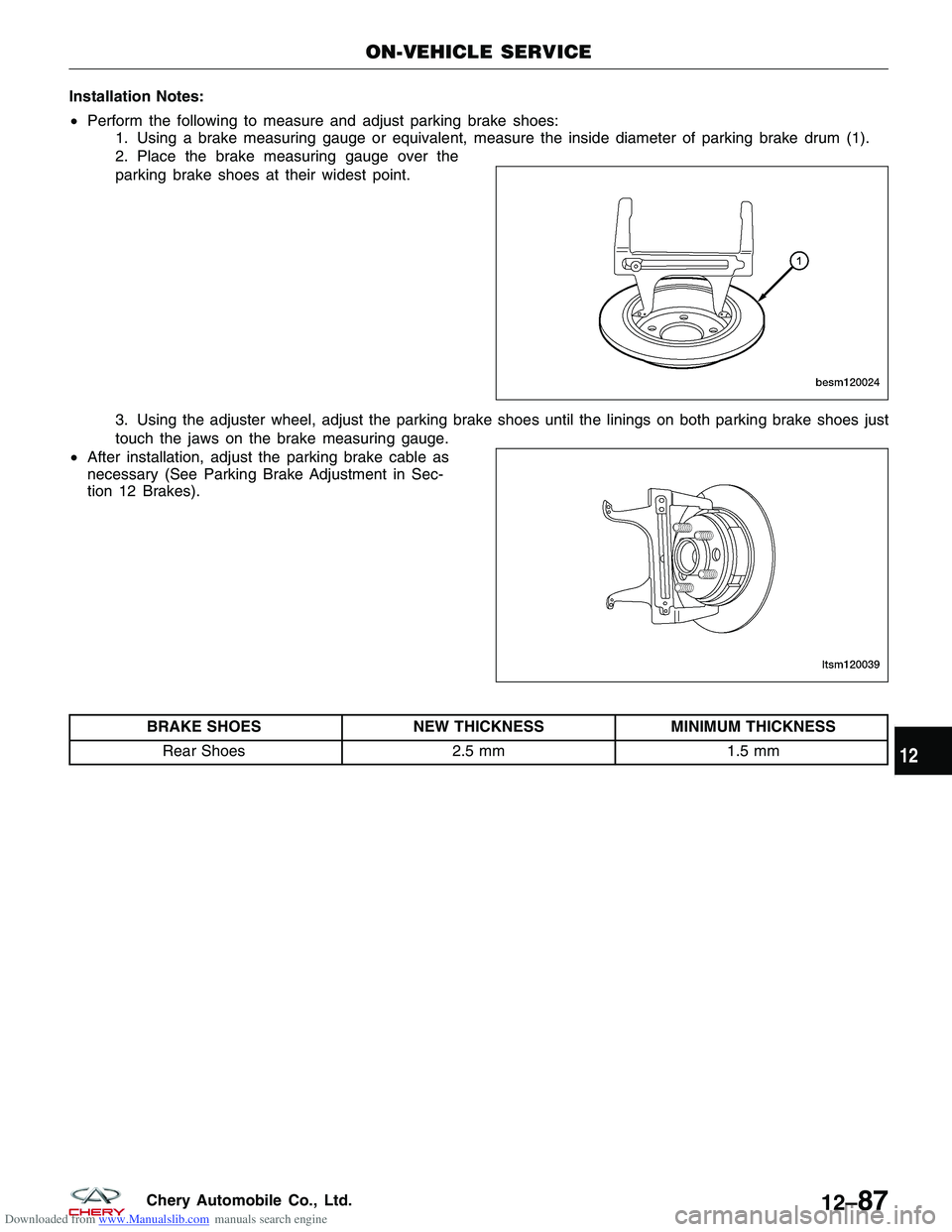
1. Using a brake measuring gauge or equivalent, measure the inside diameter of parking brake drum (1).
2. Place the brake measuring gauge over the
parking brake shoes at their widest point.
3. Using the adjuster wheel, adjust the parking brake shoes until the linings on both parking brake shoes just
touch the jaws on the brake measuring gauge.
• After installation, adjust the parking brake cable as
necessary (See Parking Brake Adjustment in Sec-
tion 12 Brakes).
BRAKE SHOES NEW THICKNESSMINIMUM THICKNESS
Rear Shoes 2.5 mm1.5 mm
ON-VEHICLE SERVICE
BESM120024
LTSM120039
12
12–87Chery Automobile Co., Ltd.
Page 1483 of 1903
Downloaded from www.Manualslib.com manuals search engine HEATING & AIR CONDITIONING
13
CONTENTSpage
Manual Temperature Control ........................................................... 13-1
System Controls .................................................................... 13-18
Air Distribution ..................................................................... 13-25
System Plumbing ................................................................... 13-32
MANUAL TEMPERATURE CONTROL
GENERAL INFORMATION13-2
Description 13-2
Operation 13-4
Specifications 13-4
Special Tools 13-5
Electrical Schematics 13-6
DIAGNOSIS & TESTING13-12
A/C System Performance 13-12 Heater Performance 13-14
ON-VEHICLE SERVICE13-15
Manual Temperature Control Module 13-15
Removal & Installation 13-15
Blower Motor Resistor 13-16
Removal & Installation 13-16
13
13–1Chery Automobile Co., Ltd.
Page 1484 of 1903
Downloaded from www.Manualslib.com manuals search engine GENERAL INFORMATION
Description
This vehicle is equipped with a common HVAC housing assembly. The system combines air conditioning, heating,
and ventilating capabilities in a single unit housing mounted under the instrument panel. The driver can choose the
following functions from HVAC control panel:
•The inside temperature
• The speed of the blower
• Five different modes of operation
• A/C compressor clutch operation
• Recirculation door position
NOTE :
To maintain the performance level of the heating, ventilation and air conditioning (HVAC) system, the engine cooling
system must be properly maintained. Any obstructions in front of the radiator or A/C condenser will reduce the per-
formance of the A/C and engine cooling systems.
13–2Chery Automobile Co., Ltd.
Page 1485 of 1903
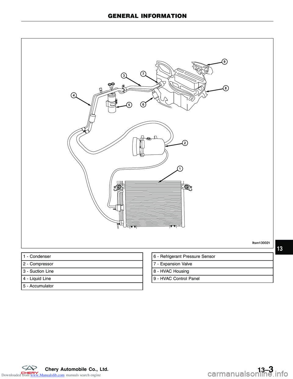
Downloaded from www.Manualslib.com manuals search engine 1 - Condenser
2 - Compressor
3 - Suction Line
4 - Liquid Line
5 - Accumulator6 - Refrigerant Pressure Sensor
7 - Expansion Valve
8 - HVAC Housing
9 - HVAC Control Panel
GENERAL INFORMATION
LTSM130021
13
13–3Chery Automobile Co., Ltd.
Page 1486 of 1903
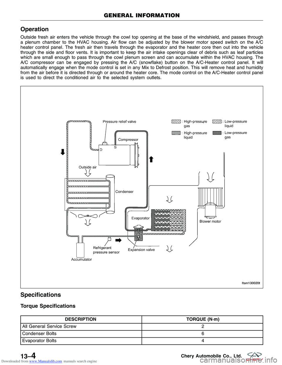
Downloaded from www.Manualslib.com manuals search engine Operation
Outside fresh air enters the vehicle through the cowl top opening at the base of the windshield, and passes through
a plenum chamber to the HVAC housing. Air flow can be adjusted by the blower motor speed switch on the A/C
heater control panel. The fresh air then travels through the evaporator and the heater core then out into the vehicle
through the side and floor vents. It is important to keep the air intake openings clear of debris such as leaf particles
which are small enough to pass through the cowl plenum screen and can accumulate within the HVAC housing. The
A/C compressor can be engaged by pressing the A/C (snowflake) button on the A/C-Heater control panel. It will
automatically engage when the mode control is set in any Mix to Defrost position. This will remove heat and humidity
from the air before it is directed through or around the heater core. The mode control on the A/C-Heater control panel
is used to direct the conditioned air to the selected system outlets.
Specifications
Torque Specifications
DESCRIPTIONTORQUE (N·m)
All General Service Screw 2
Condenser Bolts 6
Evaporator Bolts 4
GENERAL INFORMATION
LTSM130020T
13–4Chery Automobile Co., Ltd.
Page 1487 of 1903
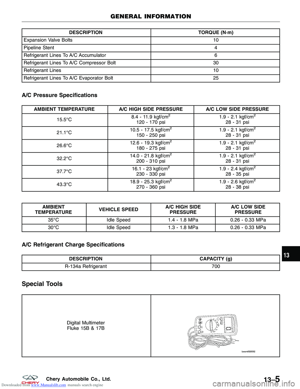
Downloaded from www.Manualslib.com manuals search engine DESCRIPTIONTORQUE (N·m)
Expansion Valve Bolts 10
Pipeline Stent 4
Refrigerant Lines To A/C Accumulator 6
Refrigerant Lines To A/C Compressor Bolt 30
Refrigerant Lines 10
Refrigerant Lines To A/C Evaporator Bolt 25
A/C Pressure Specifications
AMBIENT TEMPERATURE A/C HIGH SIDE PRESSURE A/C LOW SIDE PRESSURE
15.5°C 8.4 - 11.9 kgf/cm
2
120 - 170 psi 1.9 - 2.1 kgf/cm
2
28-31psi
21.1°C 10.5 - 17.5 kgf/cm
2
150 - 250 psi 1.9 - 2.1 kgf/cm
2
28-31psi
26.6°C 12.6 - 19.3 kgf/cm
2
180 - 275 psi 1.9 - 2.1 kgf/cm
2
28-31psi
32.2°C 14.0 - 21.8 kgf/cm
2
200 - 310 psi 1.9 - 2.1 kgf/cm
2
28-31psi
37.7°C 16.1 - 23 kgf/cm
2
230 - 330 psi 1.9 - 2.4 kgf/cm
2
28-35psi
43.3°C 18.9 - 25.3 kgf/cm
2
270 - 360 psi 1.9 - 2.6 kgf/cm
2
28-38psi
AMBIENT
TEMPERATURE VEHICLE SPEED A/C HIGH SIDE
PRESSURE A/C LOW SIDE
PRESSURE
35°C Idle Speed 1.4 - 1.8 MPa 0.26 - 0.33 MPa
30°C Idle Speed 1.3 - 1.8 MPa 0.26 - 0.33 MPa
A/C Refrigerant Charge Specifications
DESCRIPTION CAPACITY (g)
R-134a Refrigerant 700
Special Tools
Digital Multimeter
Fluke 15B & 17B
GENERAL INFORMATION
13
13–5Chery Automobile Co., Ltd.
Page 1488 of 1903
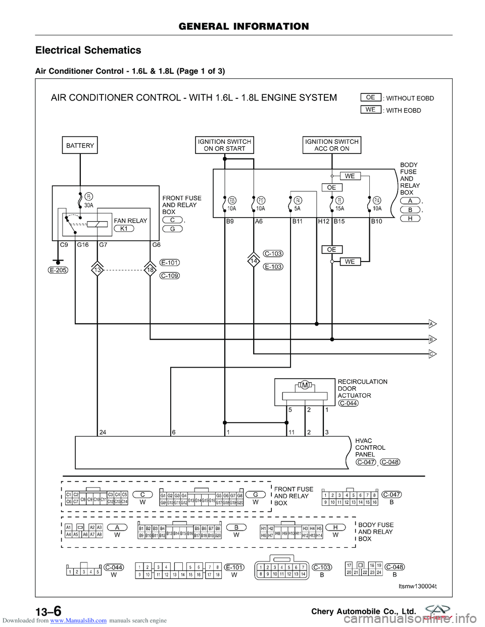
Downloaded from www.Manualslib.com manuals search engine Electrical Schematics
Air Conditioner Control - 1.6L & 1.8L (Page 1 of 3)
GENERAL INFORMATION
LTSMW130004T
13–6Chery Automobile Co., Ltd.
Page 1489 of 1903
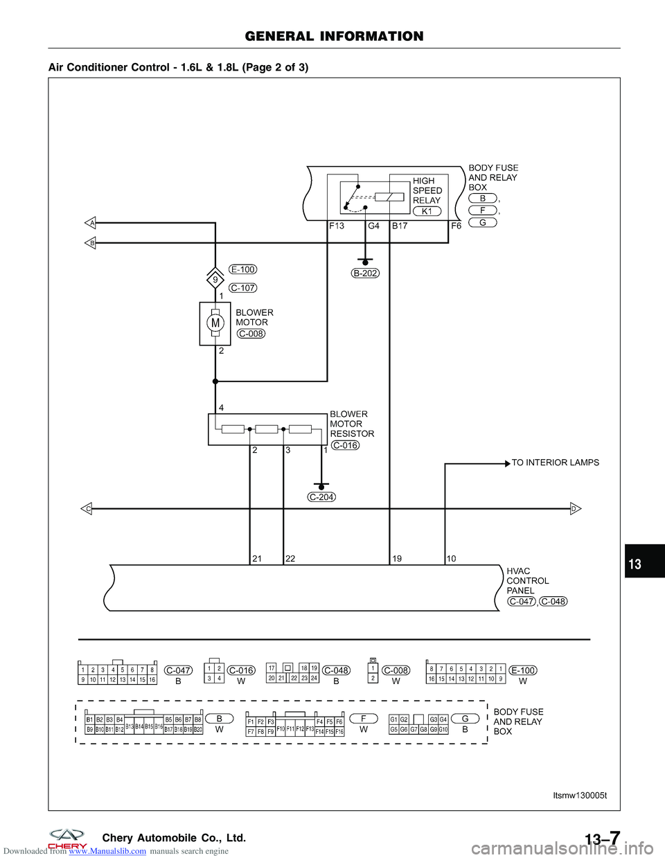
Downloaded from www.Manualslib.com manuals search engine Air Conditioner Control - 1.6L & 1.8L (Page 2 of 3)
GENERAL INFORMATION
LTSMW130005T
13
13–7Chery Automobile Co., Ltd.
Page 1490 of 1903
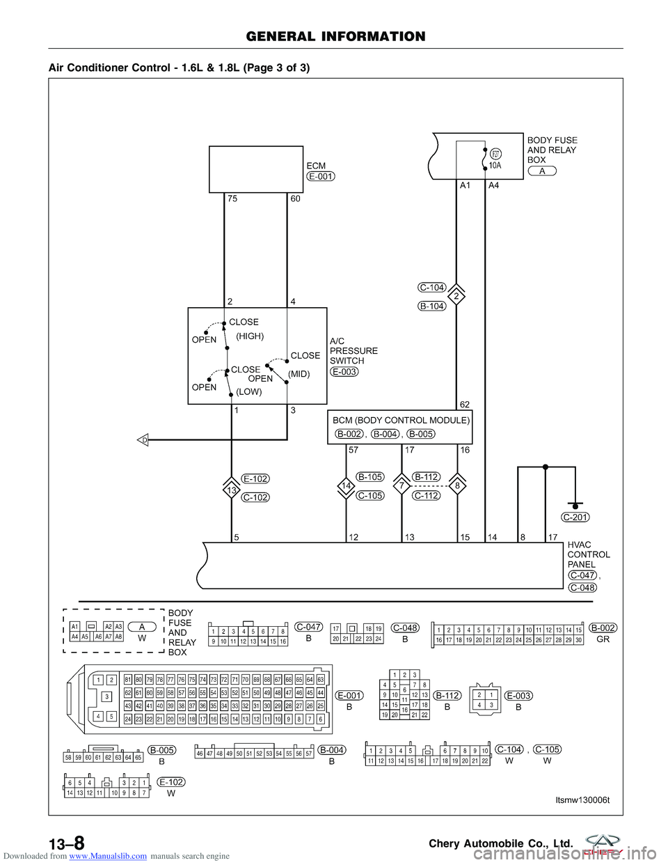
Downloaded from www.Manualslib.com manuals search engine Air Conditioner Control - 1.6L & 1.8L (Page 3 of 3)
GENERAL INFORMATION
LTSMW130006T
13–8Chery Automobile Co., Ltd.
Trending: ad blue, boot, hood open, air suspension, spare tire, audio, horn
