CHERY TIGGO 2009 Service Repair Manual
Manufacturer: CHERY, Model Year: 2009, Model line: TIGGO, Model: CHERY TIGGO 2009Pages: 1903, PDF Size: 33.38 MB
Page 1501 of 1903
Downloaded from www.Manualslib.com manuals search engine GENERAL INFORMATION
Description
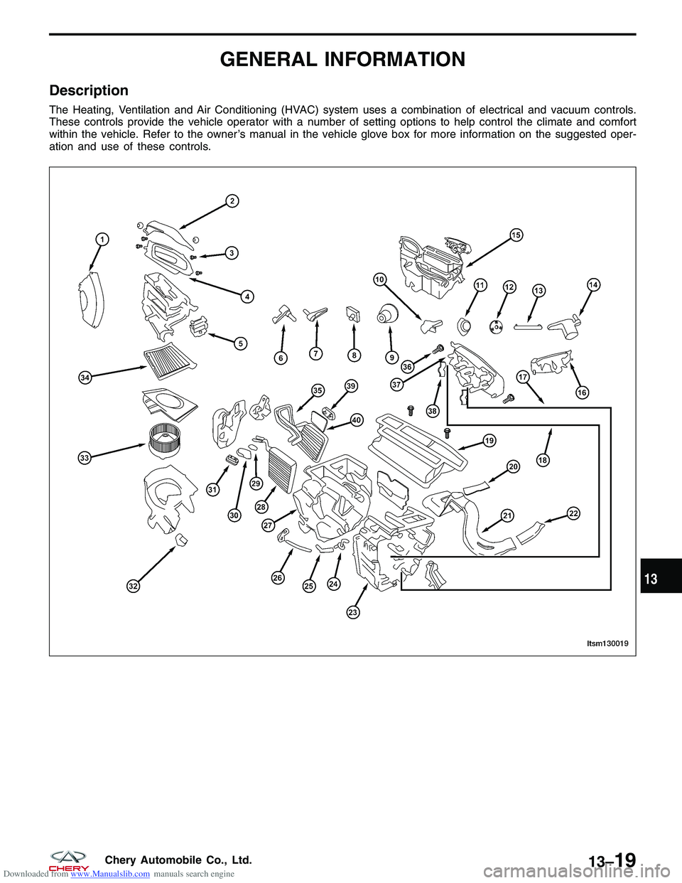
The Heating, Ventilation and Air Conditioning (HVAC) system uses a combination of electrical and vacuum controls.
These controls provide the vehicle operator with a number of setting options to help control the climate and comfort
within the vehicle. Refer to the owner’s manual in the vehicle glove box for more information on the suggested oper-
ation and use of these controls.
LTSM130019
13
13–19Chery Automobile Co., Ltd.
Page 1502 of 1903
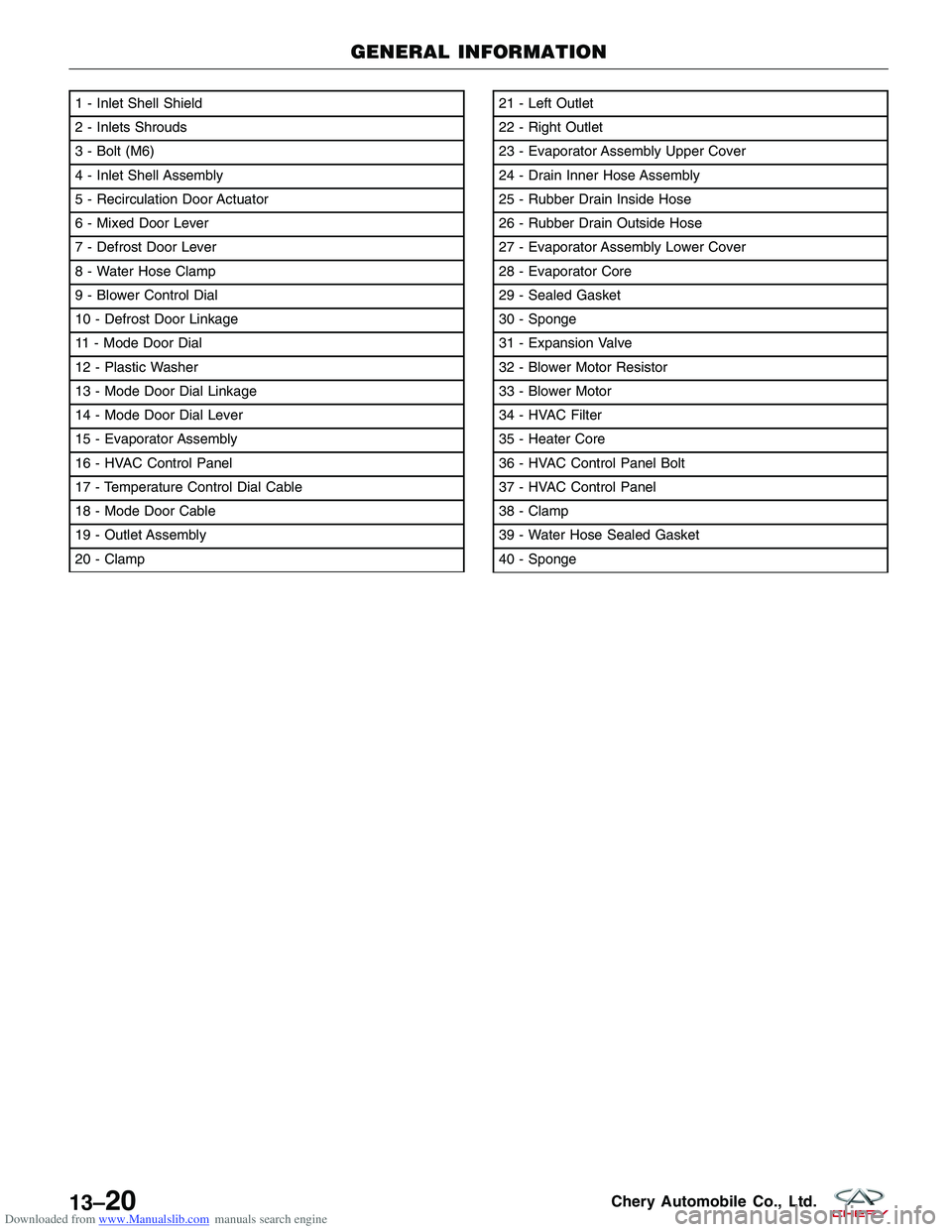
Downloaded from www.Manualslib.com manuals search engine 1 - Inlet Shell Shield
2 - Inlets Shrouds
3 - Bolt (M6)
4 - Inlet Shell Assembly
5 - Recirculation Door Actuator
6 - Mixed Door Lever
7 - Defrost Door Lever
8 - Water Hose Clamp
9 - Blower Control Dial
10 - Defrost Door Linkage
11 - Mode Door Dial
12 - Plastic Washer
13 - Mode Door Dial Linkage
14 - Mode Door Dial Lever
15 - Evaporator Assembly
16 - HVAC Control Panel
17 - Temperature Control Dial Cable
18 - Mode Door Cable
19 - Outlet Assembly
20 - Clamp21 - Left Outlet
22 - Right Outlet
23 - Evaporator Assembly Upper Cover
24 - Drain Inner Hose Assembly
25 - Rubber Drain Inside Hose
26 - Rubber Drain Outside Hose
27 - Evaporator Assembly Lower Cover
28 - Evaporator Core
29 - Sealed Gasket
30 - Sponge
31 - Expansion Valve
32 - Blower Motor Resistor
33 - Blower Motor
34 - HVAC Filter
35 - Heater Core
36 - HVAC Control Panel Bolt
37 - HVAC Control Panel
38 - Clamp
39 - Water Hose Sealed Gasket
40 - Sponge
GENERAL INFORMATION
LTSM130019
13–20Chery Automobile Co., Ltd.
Page 1503 of 1903
Downloaded from www.Manualslib.com manuals search engine Operation
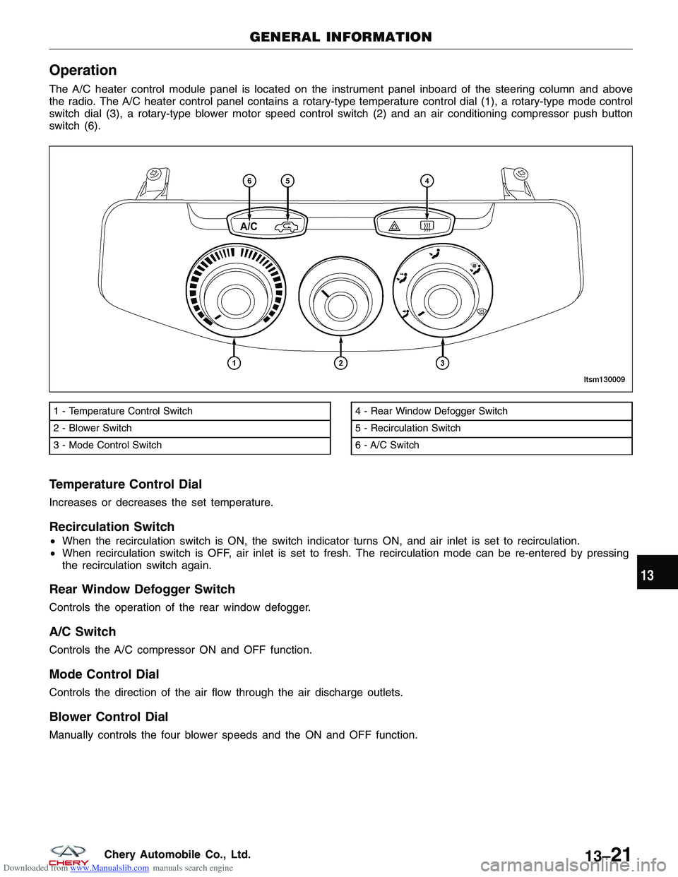
The A/C heater control module panel is located on the instrument panel inboard of the steering column and above
the radio. The A/C heater control panel contains a rotary-type temperature control dial (1), a rotary-type mode control
switch dial (3), a rotary-type blower motor speed control switch (2) and an air conditioning compressor push button
switch (6).
Temperature Control Dial
Increases or decreases the set temperature.
Recirculation Switch
•When the recirculation switch is ON, the switch indicator turns ON, and air inlet is set to recirculation.
• When recirculation switch is OFF, air inlet is set to fresh. The recirculation mode can be re-entered by pressing
the recirculation switch again.
Rear Window Defogger Switch
Controls the operation of the rear window defogger.
A/C Switch
Controls the A/C compressor ON and OFF function.
Mode Control Dial
Controls the direction of the air flow through the air discharge outlets.
Blower Control Dial
Manually controls the four blower speeds and the ON and OFF function.
1 - Temperature Control Switch
2 - Blower Switch
3 - Mode Control Switch4 - Rear Window Defogger Switch
5 - Recirculation Switch
6 - A/C Switch
GENERAL INFORMATION
LTSM130009
13
13–21Chery Automobile Co., Ltd.
Page 1504 of 1903
Downloaded from www.Manualslib.com manuals search engine Discharge Air Flow
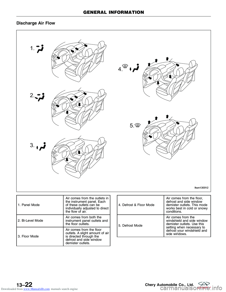
1. Panel ModeAir comes from the outlets in
the instrument panel. Each
of these outlets can be
individually adjusted to direct
the flow of air.
2. Bi-Level Mode Air comes from both the
instrument panel outlets and
the floor outlets.
3. Floor Mode Air comes from the floor
outlets. A slight amount of air
is directed through the
defrost and side window
demister outlets.4. Defrost & Floor ModeAir comes from the floor,
defrost and side window
demister outlets. This mode
works best in cold or snowy
conditions.
5. Defrost Mode Air comes from the
windshield and side window
demister outlets. Use this
setting when necessary to
defrost your windshield and
side windows.
GENERAL INFORMATION
LTSM130012
13–22Chery Automobile Co., Ltd.
Page 1505 of 1903
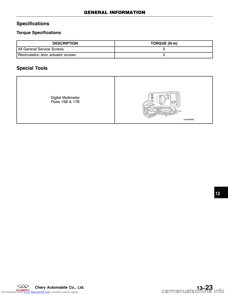
Downloaded from www.Manualslib.com manuals search engine Specifications
Torque Specifications
DESCRIPTIONTORQUE (N·m)
All General Service Screws 5
Recirculation door actuator screws 2
Special Tools
Digital Multimeter
Fluke 15B & 17B
GENERAL INFORMATION
13
13–23Chery Automobile Co., Ltd.
Page 1506 of 1903
Downloaded from www.Manualslib.com manuals search engine ON-VEHICLE SERVICE
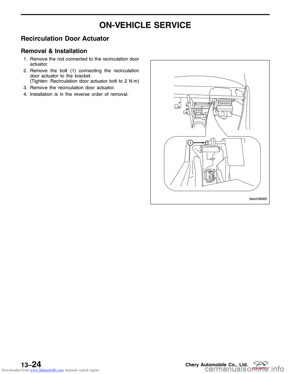
Recirculation Door Actuator
Removal & Installation
1. Remove the rod connected to the recirculation dooractuator.
2. Remove the bolt (1) connecting the recirculation door actuator to the bracket.
(Tighten: Recirculation door actuator bolt to 2 N·m)
3. Remove the recirculation door actuator.
4. Installation is in the reverse order of removal.
LTSM130003
13–24Chery Automobile Co., Ltd.
Page 1507 of 1903
Downloaded from www.Manualslib.com manuals search engine AIR DISTRIBUTION
GENERAL INFORMATION13-26
Description 13-26
Operation 13-26
Specifications 13-26
Special Tools 13-27
DIAGNOSIS & TESTING13-28
Blower Motor Electrical Troubleshooting 13-28
Blower Motor Noise 13-28
Blower Motor Vibration 13-28
ON-VEHICLE SERVICE13-29
HVAC Housing 13-29
Removal & Installation 13-29
Blower Motor 13-30
Description 13-30
Operation 13-30
Removal & Installation 13-31
13
13–25Chery Automobile Co., Ltd.
Page 1508 of 1903
Downloaded from www.Manualslib.com manuals search engine GENERAL INFORMATION
Description
All models are equipped with a common HVAC housing assembly that combines A/C and heating capabilities into a
single unit mounted within the passenger compartment. The HVAC housing assembly consists of three separate
housings:
•HVAC housing — The HVAC housing is mounted to the dash panel behind the instrument panel and contains
the A/C evaporator. The HVAC housing has mounting provisions for the air inlet housing, blower motor and the
air distribution housing.
• Air distribution housing — The air distribution housing is mounted to the rear of the HVAC housing and con-
tains the heater core, blend-air and mode-air doors and door linkage.
• Air inlet housing — The air inlet housing is mounted to the passenger side end of the HVAC housing. The air
inlet housing contains the recirculation-air door and actuator.
Operation
The A/C system is designed for the use of a non-CFC, R-134a refrigerant and uses an A/C evaporator to cool and
dehumidify the incoming air prior to blending it with the heated air. Temperature control determines the discharge air
temperature by operating the temperature control cable, which moves the blend-air door. This allows an almost
immediate control of the output air temperature of the system. The mode door cable operates the mode-air doors
which direct the flow of the conditioned air out the various air outlets, depending on the mode selected. When
equipped with A/C, the recirculation door actuator operates the recirculation-air door which closes off the fresh air
intake and recirculates the air already inside the vehicle. The electric recirculation door actuator and the blower motor
are connected to the vehicle electrical system by the instrument panel wire harness. The blower motor controls the
velocity of air flowing through the HVAC housing assembly by spinning the blower wheel within the HVAC housing at
the selected speed by use of the blower motor resistor, which is around the blower motor.
The air distribution housing must be removed from the HVAC housing and disassembled for service of the blend-air
and mode-air doors. The air inlet housing must be removed from the HVAC housing and disassembled for service of
the recirculation-air door. The HVAC housing must be removed from the vehicle and disassembled for service of the
A/C evaporator.
Specifications
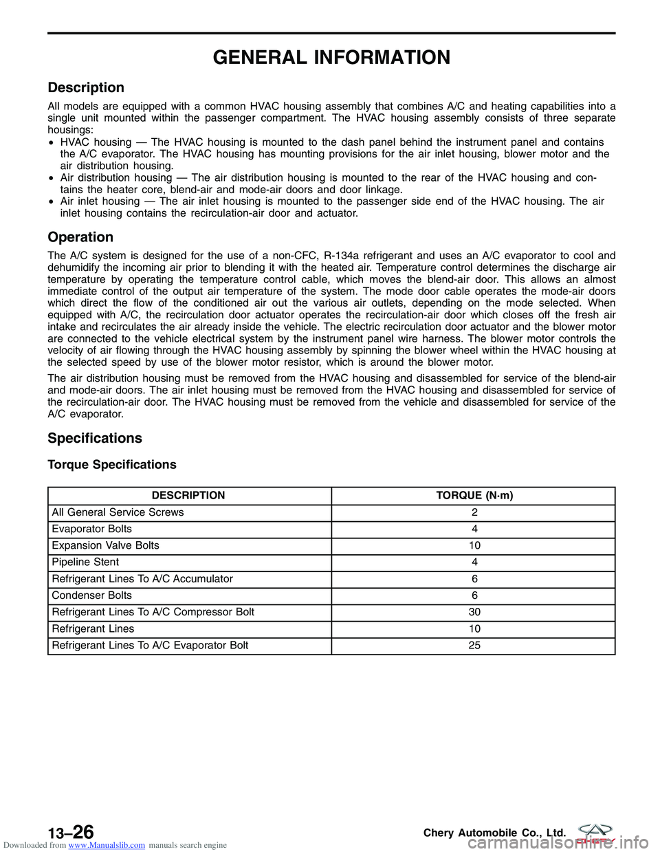
Torque Specifications
DESCRIPTION TORQUE (N·m)
All General Service Screws 2
Evaporator Bolts 4
Expansion Valve Bolts 10
Pipeline Stent 4
Refrigerant Lines To A/C Accumulator 6
Condenser Bolts 6
Refrigerant Lines To A/C Compressor Bolt 30
Refrigerant Lines 10
Refrigerant Lines To A/C Evaporator Bolt 25
13–26Chery Automobile Co., Ltd.
Page 1509 of 1903
Downloaded from www.Manualslib.com manuals search engine Special Tools
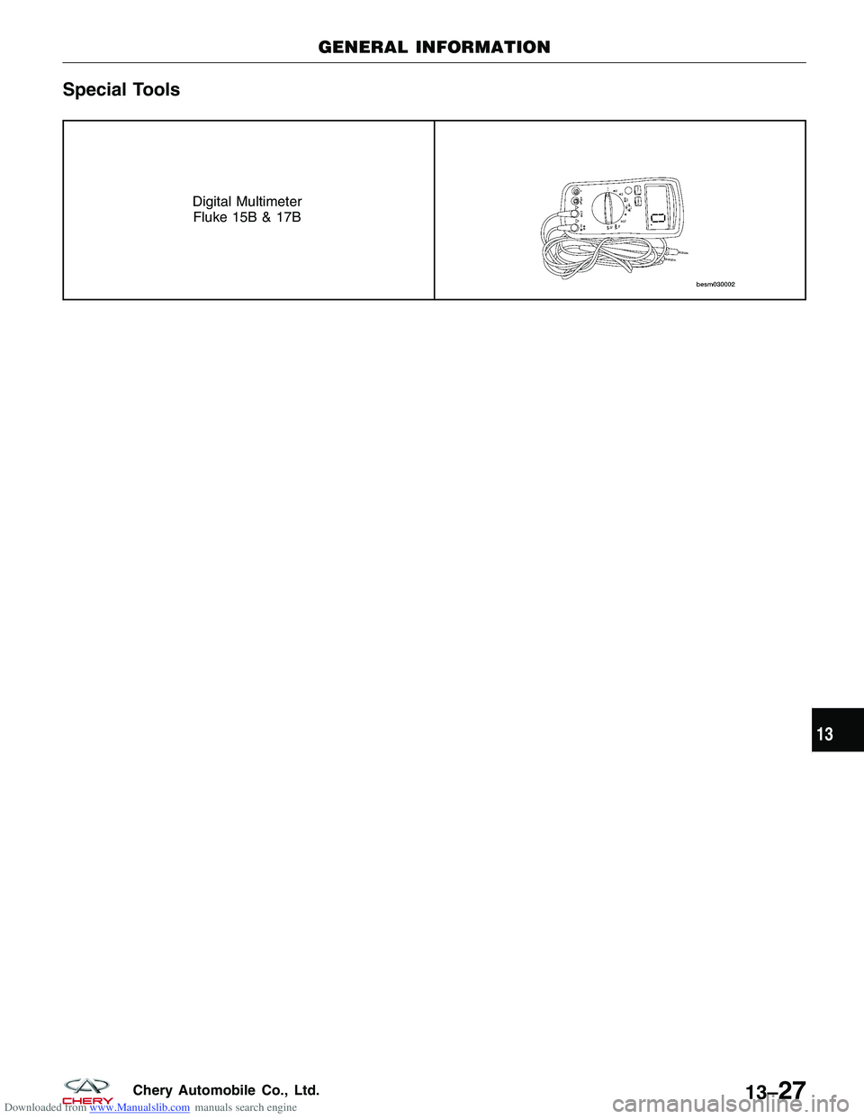
Digital MultimeterFluke 15B & 17B
GENERAL INFORMATION
13
13–27Chery Automobile Co., Ltd.
Page 1510 of 1903
Downloaded from www.Manualslib.com manuals search engine DIAGNOSIS & TESTING
Blower Motor Electrical Troubleshooting
To determine if an open condition exists within the blower motor circuit wiring, it is necessary to disconnect the neg-
ative battery cable and check for continuity within the blower motor circuits using an ohmmeter.
Possible causes of an inoperative blower motor include the following:
•Open fuse
• Inoperative blower motor switch
• Inoperative blower motor resistor
• Inoperative blower motor
• Inoperative blower motor circuit wiring or wiring harness electrical connectors
Blower Motor Noise
To determine if the blower motor is the source of the noise, simply switch the blower motor from Off to On. To verify
that the blower motor is the source of the noise, unplug the blower motor wire harness connector and operate the
heater-A/C system. If the noise goes away, possible causes include:
•Foreign material on fresh air inlet screen
• Foreign material in blower wheel
• Foreign material in HVAC housing
• Incorrect blower motor mounting
• Deformed or damaged blower wheel
• Worn blower motor bearings or brushes
Blower Motor Vibration
Possible causes of a blower motor vibration include:
•Incorrect blower motor mounting
• Foreign material in blower wheel
• Deformed or damaged blower wheel
• Worn blower motor bearings
13–28Chery Automobile Co., Ltd.