heater CHEVROLET CAMARO 1967 1.G Chassis Owners Manual
[x] Cancel search | Manufacturer: CHEVROLET, Model Year: 1967, Model line: CAMARO, Model: CHEVROLET CAMARO 1967 1.GPages: 659, PDF Size: 114.24 MB
Page 335 of 659
ENGINE-ELECTRICAL 6Y-10
circuit. Make absolutely certain all connections in
the circuit are secure.
5.
Do not short across or ground any of the terminals
on the generator or regulator.
6. Do not attempt to polarize the generator.
7.
Do not disconnect lead at generator without first dis-
connecting battery ground cable.
Trouble in the A.C. charging system will usually be
indicated by one or more of the following conditions:
1.
Faulty indicator lamp or ammeter operation.
2.
An undercharged battery (usually evidenced by slow
cranking speeds).
3.
An overcharged battery (usually evidenced by exces-
sive battery water usage).
4.
Excessive generator noise or vibration.
Described below are a series of on-the-vehicle quick
checks which are designed to assist the service tech-
nician in locating troubles within the various components
of the engine electrical system. Additional checks, ad-
justments and overhaul procedures of these components
are also described in the "Charging Systems—Service
Operations Section" and should be referred to as
necessary.
STATIC CHECKS
Before making any electrical checks, perform the fol-
lowing static checks:
1.
Check for loose fan belt.
2.
Check for defective battery. (Refer to Battery).
3.
Inspect all connections, including the slip-on con-
nectors at the regulator and Delcotron.
NOTE: Do not short field to ground to check if
generator is charging since this will seriously
damage the charging system.
SYSTEM CONDITION TEST
This test is used .to indicate the overall condition of the
charging system (both good and defective) and to isolate
the malfunctioning unit if the system is defective.
NOTE: On Corvette models difficulty may be
encountered -when attempting to make the re-
quired test connections at the voltage regulator.
It is advisable to remove the regulator from its
mounting location to perform the necessary con-
nections at the regulator for the following tests
but make sure unit is grounded.
1.
With ignition off, perform the prescribed Static
Checks outlined in this section. Then set hand brake
and shift transmission
into
neutral.
2.
Connect a voltmeter from junction block relay to
ground at regulator base.
CAUTION: Be sure meter clip does not touch a
resistor or terminal extension under regulator,
3.
Connect a tachometer on engine.
4.
Models equipped with Indicator Lamp: Turn ignition
switch on "ON" position and check indicator lamp.
If lamp fails to glow, perform appropriate tests and
corrections (Indicator Lamp Circuit Tests) before
continuing.
Models equipped with Ammeter: Turn ignition
switch to "ACC" with an accessory on and check
ammeter. If ammeter fails to read discharge, check
ammeter circuit before continuing.
5.
Models equipped with Indicator Lamp: If lamp glows,
start the engine and run' it at 1500 rpm or above.
Check indicator lamp. If lamp fails to go out, per-
form appropriate test and corrections (Indicator
Lamp Circuit Test) before continuing.
Models equipped with Ammeter: If ammeter reads
discharge, start the engine and observe ammeter. If
meter fails to move toward charge (from original
position), perform appropriate test and corrections
(Field Circuit Tests) before continuing.
NOTE: At this point a field circuit has been
established and any other problem will lie in
generator or regulator.
6. Turn on high-beam headlights and heater blower
motor to high speed, run engine at or above 1500
rpm (for a few minutes, if necessary) and read the
voltage on meter.
AIR GAP
ADJUSTING NUT
ONLY
ADJUSTING SCREW
(Turn To Adjust
Voltage Setting)
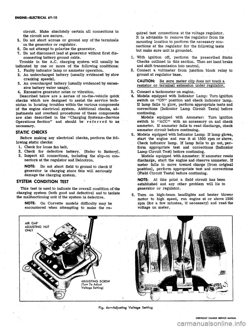
Fig.
6c—Adjusting Voltage Setting
CHEVROLET CHASSIS SERVICE MANUAL
Page 355 of 659

ENGINE-ELECTRICAL-6Y-30
Fig.
2 li—Removing Ignition Switch Nut
4.
Remove heater and/or A/C control panel assembly
retaining screws and push panel assembly from
console.
NOTE: If interference between control panel
and radio is encountered, loosen radio retaining
nuts.
5.
Remove radio control knobs, bezels and retaining
nuts.
6. Disconnect radio wiring harness and antenna lead-in.
7.
Remove radio rear brace attaching screw and re-
move radio from vehicle.
Fig.
231—Switch and Connector Unplugged
8. Remove ignition switch bezel nut using Tool J-7607
and push switch rearward from panel opening.
9. Disconnect wiring connector from rear of switch.
10.
To install, reverse removal procedure.
SPARK PLUGS
CLEANING AND REGAPPING
Clean the spark plugs thoroughly, using an abrasive-
type cleaner. If the porcelains are badly glazed or
blistered, the spark plugs should be replaced. All spark
plugs must be of the same make and number or heat
range. Use a round feeler gauge to adjust the spark plug
gap to specifications (fig. 24i).
Fig.
22i—Unlocking Ignition Switch Connector
Fig.
241—Setting Sfxirk Plug Gap
CHEVROLET CHASSIS SERVICE MANUAL
Page 533 of 659
ELECTRICAL-BODY AND CHASSIS 12-21
2.
Remove ash tray, retainer attaching screws and
retainer.
3.
Remove Air Conditioning distributor
duct'
retaining
screws and duct.
4.
Remove heater and/or Air Conditioning control panel
assembly retaining screws and push panel assembly
from console.
NOTE:
If interference between control panel
and radio is encountered, loosen radio retaining
nuts.
5. Remove radio control knobs, bezels and retaining
nuts.
6. Disconnect radio wiring harness and antenna lead-in.
7. Remove radio rear brace attaching screw and re-
move ra(Jio from vehicle.
8. Remove ignition switch bezel nut using Tool J-7607
and push switch rearward.
9. Disconnect cigarette wiring connector.
10.
Remove cigarette lighter retainer and lighter as-
sembly from console.
11.
To install, reverse removal procedure.
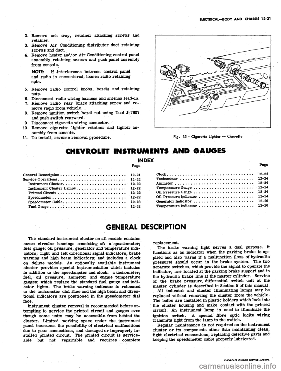
Fig.
35 - Cigarette Lighter — Chevelle
CHEVROLET INSTRUMENTS AND GAUGES
INDEX
Page
General Description 12-21
Service Operations 12-22
Instrument Cluster........................ 12-22
Instrument Cluster Lamps 12-22
Printed Circuit .
* •
12-22
Speedometer 12-22
Speedometer Cable 12-23
Fuel Gauge 12-23
Page
Clock 12-24
Tachometer 12-24
Ammeter . . 12-24
Temperature Gauge 12-24
Oil Pressure Gauge 12-24
Oil Pressure Indicator 12-24
Generator Indicator 12-26
Temperature Indicator 12-26
GENERAL DESCRIPTION
The standard instrument cluster on all models contains
seven circular housings consisting of: a speedometer;
fuel gauge; oil pressure, generator and temperature indi-
cators; right and left directional signal indicators; brake
warning and high beam indicators; and includes a clock
on deluxe models. An optionally available instrument
cluster provides special instrumentation which includes
in addition to the speedometer and clock: a tachometer;
fuel, oil pressure, ammeter and engine temperature
gauges; which replace the standard fuel gauge and indi-
cator lights. The brake warning indicator is relocated
to the tachometer dial face and the high beam and direc-
tional indicators are positioned in the speedometer dial
face.
Instrument cluster removal is recommended before at-
tempting to service the printed circuit and gauges even
though some units may be accessible from behind the
cluster. Limited working space under the instrument
panel increases the possibility of electrical malfunctions
due to poor connections, and damaged or improperly in-
stalled printed circuit. The printed circuit is service-
able but not repairable and requires complete
replacement.
The brake warning light serves a dual purpose. It
functions as an indicator when the parking brake is ap-
plied and also warns if a malfunction (loss of hydraulic
pressure) should occur in the brake system. The two
separate switches, which provide the signal to operate the
indicator, are located at the parking brake support and in
the hydraulic brake line at the master cylinder. Service
of the brake pressure, differential switch unit at the
master cylinder is described in Section 5 of this manual.
All indicator and cluster illumihating lamps may be
replaced without removing the cluster from the vehicle.
The bulbs are installed in plastic holders which lock into
the cluster housing and make contact with the printed
circuit. An instrument lamp is used to illuminate the
ignition switch. A special fibre optic lucite wiring
transmits light from the lamp to the switch.
Regular maintenance is not required on the instrument
cluster or its components other than maintaining clean,
tight electrical connections, replacing defective parts and
keeping the speedometer cable properly lubricated.
CHEVROLET CHASSIS SERVICE MANUAL
Page 537 of 659
10
27
18
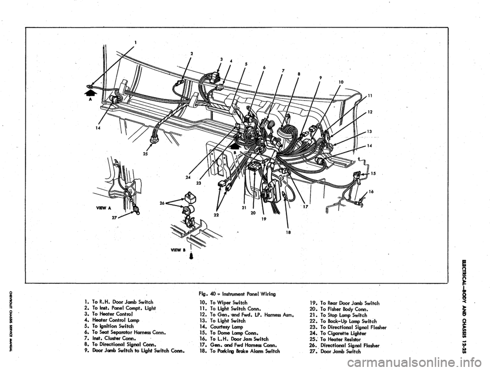
1.
To R. H. Door Jamb Switch
2.
To Inst. Pane! Compt. Light
3. To Heater Control
4. Heater Control Lamp
5. To Ignition Switch
6. To Seat Separator Harness Conn.
7. Inst. Cluster Conn.
8. To Directional Signal Conn.
9.
Door Jamb Switch to Light Switch Conn,
Fig.
40 - Instrument Panel Wiring
10.
To Wiper Switch
11.
To Light Switch Conn.
12.
To Gen. and Fwd. LP. Harness Asm,
13.
To Light Switch
14.
Courtesy Lamp
15.
To Dome Lamp Conn.
16.
ToL.H. Door Jam Switch
17.
Gen. and Fwd Harness Conn.
18.
To Paricing Brake Alarm Switch
19.
To Rear Door Jamb Switch
20.
To Fisher Body Conn.
21.
To Stop Lamp Switch
22.
To Back-Up Lamp Switch
23.
To Directional Signal Flasher
24.
To Cigarette Lighter
25.
To Heater Resistor
26.
Directional Signal Flasher
27.
Door Jamb Switch
Page 542 of 659
VIEW
A
VIEW
B
(13700-800)
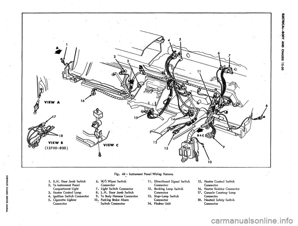
Fig. 44
-
Instrument Panel Wiring Harness
1.
R.H. Door Jamb Switch
2.
To Instrument Panel
Compartment Light
3. Heater Control Lamp
4.
Ignition Switch Connector
5. Cigarette Lighter
Connector
6. W/S Wiper Switch
Connector
7. Light Switch Connector
8.
L.H.
Door Jamb Switch
9.
To
Body Harness Connector
10.
Parking Brake Alarm
Switch Connector
11.
Directional Signal Switch
Connector
12.
Backing Lamp Switch
Connector
13.
Stop-Lamp Switch
Connector
14.
Flasher Unit
15.
Heater Control Switch
Connector
16.
Heater Resistor Connector
17.
Console Courtesy Lamp
Connector
18.
Neutral Safety Switch
Connector
Page 545 of 659
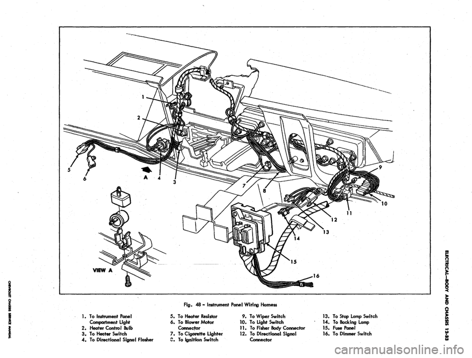
Fig.
48 - Instrument Panel Wiring Hamess
1.
To Instrument Panel
Compartment light
2.
Heater Control Bulb
3. To Heater Switch
4.
To Directional Signal Flasher
5.
6.
7.
a
To Heater Resistor
To Blower Motor
Connector
To Cigarette Lighter
To Ignition Switch
9.
10.
11.
12.
To Wiper Switch
To Light Switch
To Fisher Body Connector
To Directional Signal
Connector
13.
To Stop Lamp Switch
14.
To Backing Lamp
15.
Fuse Panel
16.
To Dimmer Switch
Page 551 of 659

17-
VIEW A
Fig.
53 - Instrument Panel Wiring Harness
1.
To Glove Box Light
2.
To Heater Control
3. Heater Control Lamp
4. To Cigarette Lighter
5. To Ignition Switch
6. To Instrument Cluster
7. To Wiper Switch
8. To Light Switch
9.
To Directional Signal Switch
10.
To Stop Lamp Switch
11.
To Backing Lamp Switch
12.
Fuse Panel
13.
To Dimmer Switch
14.
To Fisher Body Connector
15.
To Directional Signal Flasher
16.
To Heater Resistor
17.
Directional Signal Flasher
Page 574 of 659
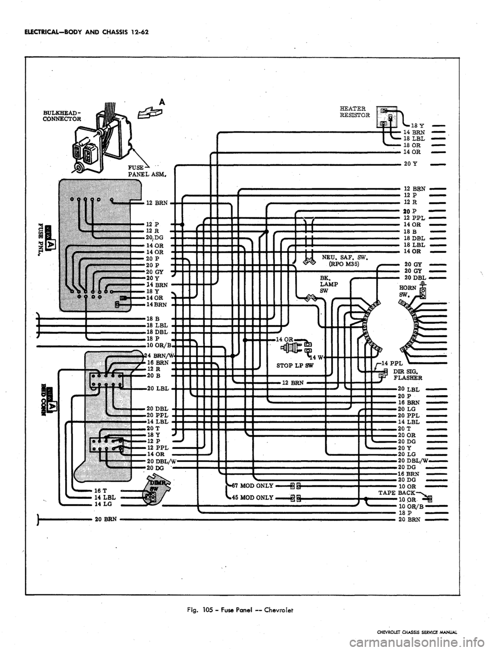
ELECTRICAL-BODY
AND
CHASSIS
12-62
BULKHEAD-
CONNECTOR
HEATER
RESISTOR
PANEL ASM.
12 BRN
20
Y
12 BRN
»-67 MOD ONLY
*45 MOD ONLY
14 PPL
DIRSIG.
FLASHER
20 BRN
'20 LBL
20
P
16 BRN
>20
LG
• 20 PPL
•
14 LBL
• 20
T
.20 OR
-20 DG
20
Y
20
LG
—
20DBL/W.
20
DG
—16 BRN
20 DG
10
OR
TAPE BACK
'10 OR
10 OR/B
18
P
20 BRN
Fig.
105 -
Fuse Panel
—
Chevrolet
CHEVROLET CHASSIS SERVICE MANUAL
Page 575 of 659
ELECTRICAL-BODY AND CHASSIS 12-63
R.H. COURTESY
LP,
(67 MODELS &
16600 ONLY)
•18Y
R. H. DOOR JAMB
SW
(ALL EXCEPT 15300-400)
BK.
NEU.
LP.SW.SAF.SW.
(RJ»JD^
20 OR
20 OR
COMPT
(U*INST. PANEL COMP. LAMP
R-i3r
(ALL EXCEPT 15300-400)
14BRN
18
LBL
18 OR
14 OR
HEATER
CONTROL
LP.
RADIO CONN.
CIG.
LGT
20
P —
4
PPL
20
LG'
14 PPL—
NSOLE
CONN.
(16700-800
ONLY)
CONSOLE
CONN.
(16700-800
ONLY)
12
PPL
14 OR
12 PPL/W
20
GY/B
20 OR
14 OR
20 OR
14 OR
20 OR
20DBL
20 OR
20
GY
INSTRUMENT
CLUSTER
-ILLUM
-ILLUM
-R.H.
S
-GEN
-OILP
-ILLUM
-ILLUM
20 GY
20 GY
20DBI
20DBL/W
18
W
16BRN
-CLOCK-—:(i??T0°)
-ILLUM
^™LY
18
B
18
DBL
18
LBL
-HIGH BEAM—(11
-ILLUM
-
FUEL-GAGE —{30
-ILLUM
-ILLUM-^
-PARK BRAKE
ALARM & BRAKE
WARN. LIGHT
-ENG TEMP.—(35),
(39
-L.H.
SIG.
LAMP—(14
-ILLUM
-
TRAFFIC
HAZARD
SW.
20
LBL
20
P
16BRN
20
LG
20
PPL
14
LBL
20
T
20 OR
20 DG
20 OR
20
t
20 DG
20
Y
20
LG
20
BRN
12
PPL
PARK BRAKE
SW.
20 DBL/W
20 DG
12R
20 DG
10 OR
12
GY
20 OR
18
W
18
W
14
LBL
14T/W
14
B
SW.
67
MOD ONLY
L.H. COURT
LP.
(67 MODELS
&
16600 ONLY)
18 W-'
T/G WINDOW
SW.
(45 MOD ONLY)
DOOR JAMB
SW.
(ALL EXCEPT 15300-400)
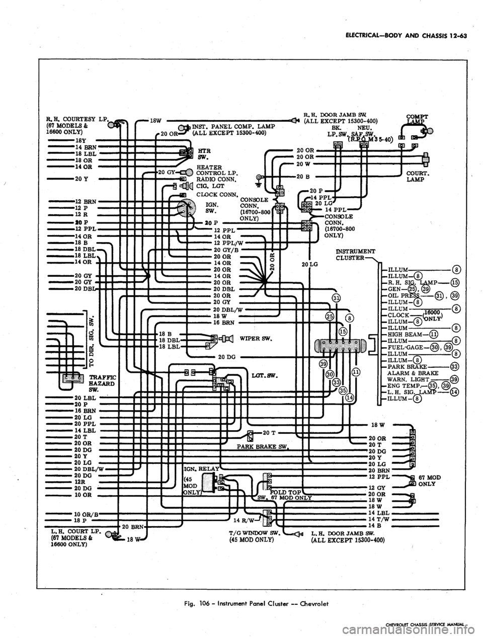
Fig.
106 - Instrument Panel Cluster ~ Chevrolet
CHEVROLET CHASSIS SERVICE MANUAL
Page 580 of 659
ELECTRICAL-BODY AND CHASSIS 12-68
-7«3« R.H. DR. JAMB.SW.
C_18W-^{|>R.H. COURT
es RADIO CONN.
c5£ siHp INST. PANEL
COMPT. LAMP
ALL EXCEPT
(13100-400)
HEATER
CONTROL
HTR. CONTROL
LAMP
IGNITION SW.
LGT.
R. TURN IND.
INST.'CL. LP.
HEATER
RESISTOR
18 OR
20 Y
12 PPL/W
12 R
12 P
20 DG
14BRN
12 BRN
24 BRN/W
14
OR
20 GY
12 PPL/W
12 R
12 P
24 BRN/W
14
OR
BRK. ALARM
IND.
HI BEAM
IND.
LP.
GEN. IND. LP.
TEMP. IND. LP
INST* CL. LP.
OIL PRESS
IND.
LP.
HORN BUTTON
TO TRAFFIC
HAZARD SW.
20DBL
INST. CL. LP.
INST. CL. LP.
18 LBL
18 B
18DBL
r—20
BRN
20 OR
20
OR
20 PPL
4 LBL
20 DG
12 R
18 OR
BODY HARNESS
18 W—O-18W
^-20 BRN
20 LG
20 Y
20 DG
L.H. DR. JAMB SW.
20 LG
20 Y
20 DG
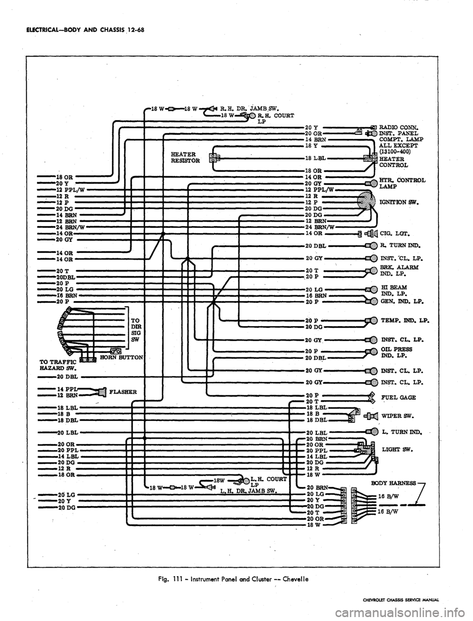
Fig.
Ill - Instrument Panel and Cluster — CheveNe
CHEVROLET CHASSIS SERVICE MANUAL