lock CHEVROLET CAMARO 1967 1.G Chassis Workshop Manual
[x] Cancel search | Manufacturer: CHEVROLET, Model Year: 1967, Model line: CAMARO, Model: CHEVROLET CAMARO 1967 1.GPages: 659, PDF Size: 114.24 MB
Page 250 of 659
BRAKES 5-17
mended shoe and lining assemblies. Otherwise,
serious fade or failure may occur.
1.
Inspect new linings and make certain there are no
nicks or burrs on bonding material on shoe edge
where contact is made with brake flange plate or
on any of the contact surfaces.
NOTE: Keep hands clean while handling brake
shoes.
Do not permit oil or grease to come in
contact with linings.
2.
If working on rear brakes, lubricate parking brake
cable.
3.
On rear brakes only, lubricate fulcrum end of park-
ing brake lever and the bolt with brake lube, then
attach lever to secondary shoe with bolt, spring
washer, lock washer and nut. Make sure that lever
moves freely.
4.
Before installation make certain the adjusting screw
is clean and lubricated properly.
NOTE: Loose adjustment may occur from an
adjusting screw that is not properly operating.
If the lubrication in the adjusting screw as-
sembly is contaminated or destroyed, the ad-
justing screw should be thoroughly cleaned and
lubricated.
5.
Connect brake shoes together with adjusting screw
spring, then place adjusting screw, socket and nut
in position.
CAUTION: Make sure the proper adjusting
screw is used ("L" for left side of vehicle,
"R"
for right side of vehicle). The star wheel
should only be installed with the star wheel
nearest to the secondary shoe and the adjusting
screw spring inserted to prevent interference
with the star wheel.
6. On rear wheels connect parking brake cable to lever.
7.
Secure the primary brake shoe (short lining—faces
forward) first with the hold-down pin and spring
using a pair of pliers. Engages shoes with the wheel
cylinder connecting links.
8. Install and secure the actuator assembly and second-
ary brake shoe with the hold-down pin and spring
using a pair of needle nose pliers. On rear wheels
position parking brake strut and strut spring.
9. Install guide plate over anchor pin.
10.
Install the wire link.
NOTE: Do not hook the wire link over the
anchor pin stud with the regular spring hook
tool. This may damage the cylinder boot seals.
Fasten the wire link to the actuator assembly ;
first, then place over the anchor pin stud by
hand while holding the adjuster assembly in the
full down position.
11.
Install actuator return spring.
NOTE: Do not pry actuator lever to install re-
turn spring. Ease it in place using the end of a
screw driver or other suitable flat tool.
12.
If old brake pull back (return) springs are nicked,
distorted or if strength is doubtful, install new
springs.
13.
Hook springs in shoes using Tool J-8049 by in-
stalling the primary spring from the shoe over the
anchor pin and then spring from secondary shoe
over the wire link end.
14.
Pry shoes away from backing plate and lubricate
shoe contact surfaces with a thin coating of brake
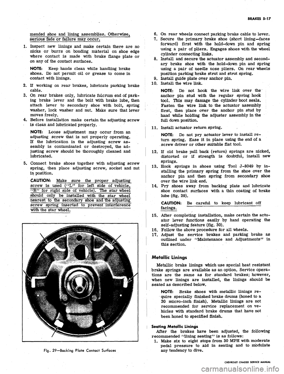
lube (fig. 29).
CAUTION:
facings.
Be careful to keep lubricant off
Fig.
29—Backing Plate Contact Surfaces
15.
After completing installation, make certain the actu-
ator lever functions easily by hand operating the
self-adjusting feature (fig. 30).
1.6. Follow the above procedure for all wheels.
17.
Adjust the service brakes and parking brake as
outlined under "Maintenance and Adjustments" in
this section.
Metallic Linings
Metallic brake linings which use special heat resistant
brake springs are available as an option. Service opera-
tions are the same as for standard brakes; however,
when new linings are installed, the linings should be
seated as described below.
NOTE: Brake shoes with metallic linings re-
quire specially finished brake drums (honed to a
20 micro-inch finish). Metallic linings are not
recommended for service replacement on ve-
hicles with standard brake drums that have not
been honed to specified finish.
Seating Metallic Linings
After the brakes have been adjusted, the following
recommended "lining seating" is as follows:
1.
Make six to eight stops from 30 MPH with moderate
pedal pressure to aid in seating and to mbdulate
any tendency to dive.
CHEVROLET CHASSIS SERVICE MANUAL
Page 254 of 659
BRAKES 5-21
brake fluid. Coat the primary and secondary seals
on the secondary piston with clean brake fluid. Insert
the secondary piston spring retainer into the sec-
ondary piston spring. Place the retainer and spring
down over the end of the secondary piston until the
retainer locates inside of the lips of the primary
cup.
10.
Hold the master cylinder with the open end of the
bore down. Push the secondary piston into the bore
until the spring seats against the closed end of the
bore.
11.
Position the master cylinder in a vise with the
open end of the bore up. Coat the primary and
secondary seal on the primary piston with clean
brake fluid. Push the primary piston assembly,
spring end first, into the bore of the master cylinder*
Hold the piston down and snap the lock ring into
position in the small groove in the I.D. of the bore.
12.
Push the primary piston down to move the secondary
piston forward far enough to clear the stop screw
hole in the bottom of the front fluid reservoir. Install
the stop screw.
13.
Install reservoir diaphragm in the reservoir cover
and install the cover on the main cylinder. Push
bail wire into position to secure the reservoir cover.
Installation
1.
Assemble the push rod through the push rod retainer,
if it has been disassembled.
2.
Push the retainer over the end of the main cylinder.
Assemble new boot over push rod and press it down
over the push rod retainer. Slide new mounting
gasket into position.
3.
Secure .the main cylinder to the firewall with mount-
ing bolts.
4.
Connect the push rod clevis to the brake pedal with
pin and retainer.
5. Connect the brake lines to the main cylinder.
6. Fill the main cylinder reservoirs to the levels
shown in Figure 8. Bleed the brake system as out-
lined in this section.
7. K necessary, adjust the brake pedal free play as
outlined in this section.
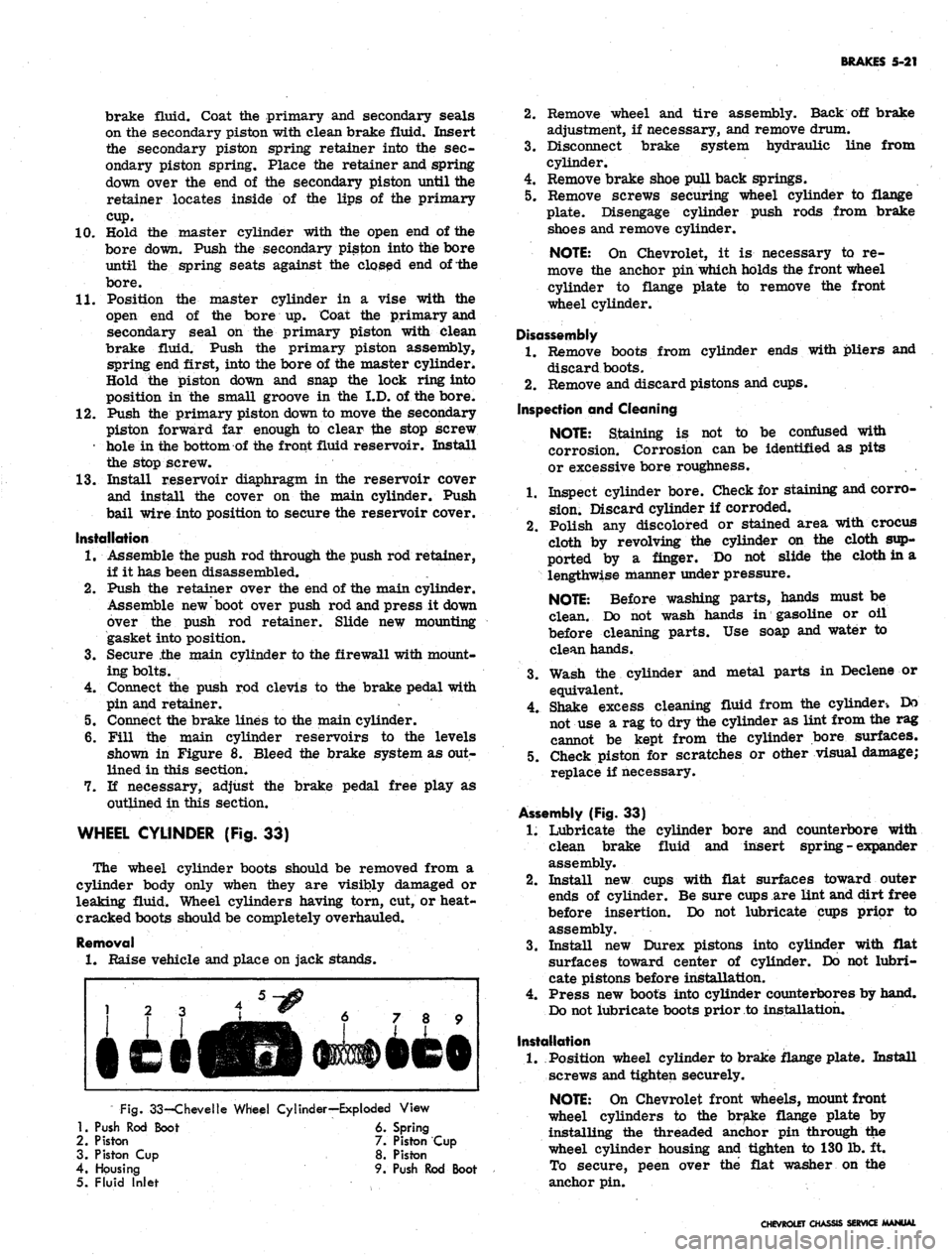
WHEEL CYLINDER (Fig. 33)
The wheel cylinder boots should be removed from a
cylinder body only when they are visibly damaged or
leaking fluid. Wheel cylinders having torn, cut, or heat-
cracked boots should be completely overhauled.
Removal
1.
Raise vehicle and place on jack stands.
Fig.
33-Chevelle Wheel Cylinder—Exploded View
1.
Push Rod Boot 6. Spring
2.
Piston 7. Piston Cup
3. Piston Cup 8. Piston
4.
Housing 9. Push Rod Boot
5. Fluid Inlet
2.
Remove wheel and tire assembly. Back off brake
adjustment, if necessary, and remove drum.
3.
Disconnect brake system hydraulic line from
cylinder.
4.
Remove brake shoe pull back springs.
5. Remove screws securing wheel cylinder to flange
plate. Disengage cylinder push rods from brake
shoes and remove cylinder.
NOTE:
On Chevrolet, it is necessary to re-
move the anchor pin which holds the front wheel
cylinder to flange plate to remove the front
wheel cylinder.
Disassembly
1.
Remove boots from cylinder ends with pliers and
discard boots.
2.
Remove and discard pistons and cups.
Inspection and Cleaning
NOTE:
Staining is not to be confused with
corrosion. Corrosion can be identified as pits
or excessive bore roughness.
1.
Inspect cylinder bore. Check for staining and corro-
sion.
Discard cylinder if corroded.
2.
Polish any discolored or stained area with crocus
cloth by revolving the cylinder on the cloth sup-
ported by a finger. Do not slide tfce cloth in a
lengthwise manner under pressure.
NOTE:
Before washing parts, hands must be
clean. Do not wash hands in gasoline or oil
before cleaning parts. Use soap and water to
clean hands.
3.
Wash the cylinder and metal parts in Declene or
equivalent.
4.
Shake excess cleaning fluid from the cylinder-. Do
not use a rag to dry the cylinder as lint from the rag
cannot be kept from the cylinder bore surfaces.
5. Check piston for scratches or other visual damage;
replace if necessary.
Assembly (Fig. 33)
1.
Lubricate the cylinder bore and counterbore with
clean brake fluid and insert spring - expander
assembly.
2.
Install new cups with flat surfaces toward outer
ends of cylinder. Be sure cups are lint and dirt free
before insertion. Do not lubricate cups prior to
assembly.
3.
Install new Durex pistons into cylinder with flat
surfaces toward center of cylinder. Do not lubri-
cate pistons before installation.
4.
Press new boots into cylinder counterbores by hand.
Do not lubricate boots prior to installation.
Installation
1.
Position wheel cylinder to brake flange plate. Install
screws and tighten securely.
NOTE:
On Chevrolet front wheels, mount front
wheel cylinders to the brake flange plate by
installing the threaded anchor pin through the
wheel cylinder housing and tighten to 130 lb. ft.
To secure, peen over the flat washer on the
anchor pin.
CHEVROLET CHASSIS SERVICE MANUAL
Page 255 of 659
BRAKES 5-22
2.
Replace ail push rods and pull back springs.
3.
Connect hose or line to wheel cylinder.
NOTE:
If replacing front wheel cylinder, con-
nect hose and inspect installation as outlined in
"Hydraulic Brake Hose Replacement".
4.
Install drum and wheel.
5. Bleed brakes as outlined in this section.
ANCHOR PIN
Front Wheel
1.
Raise front of vehicle and place on jack stands.
2.
Remove wheel and drum as outlined in this section.
3.
Remove brake shoe pull back springs, link and guide
plate.
4.
Disengage anchor pin lock and remove anchor pin by
turning counterclockwise.
5. Place new lock plate on anchor pin and pass pin
through the hole in flange plate and screw into tapped
hole in spindle support.
6. Torque pin to 130 lb. ft. and lock by peening over
washer tabs.
7. Install brake shoe guide plate, link and pull back
springs.
8. Adjust brakes, install drum and wheel as outlined
in this section. Test brake operation.
Rear Wheel
Two type anchor pins are used in production for the
rear wheels. The riveted type is not serviced and if
failure or damage should occur to either the anchor
pin or flange plate, both parts will have to be replaced
and the threaded type anchor pin used.
Threaded Type
1.
Raise rear of vehicle and place on jack stands,
2.
Remove wheel and drum as outlined in this section.
3.
Remove brake shoe pull back springs, link and guide
plate.
4.
Remove anchor pin retaining nut and washer and
remove pin from flange plate.
5. Position anchor pin to flange plate, install lock
washer and nut, and torque pin to 80 lb. ft.
6. Install brake shoe guide plate, link and pull back
springs.
7. Adjust brakes and install drum and wheel as outlined
in this section.
8. Test brake operation.
BRAKE DRUMS
Front brake drums are the demountable type; that is,
they can be removed without removing the hub. Rear
brake drums are demountable and may be removed
wihtout removing the axle shaft.
A lanced "knock out" area (fig. 34) is provided in
the web of the brake drum for servicing purposes in
the event retracting of the brake shoes is required in
order to remove the drum.
A small screw driver or hooked wire may be inserted
to disengage the automatic adjuster actuating lever so
the star wheel may be turned.
Removal
1.
Raise vehicle and place on jack stand.
2.
Remove wheel and tire assembly, back off brake
adjustment and remove drum.
Inspection and Reconditioning
Whenever brake drums are removed they should be
thoroughly cleaned and inspected for cracks, scores,
deep grooves, and out-of-round. Any of these conditions
must be corrected since they can impair the efficiency
of brake operation and also can cause premature failure
of other parts.
Smooth up any slight scores by polishing with fine
emery cloth. Heavy or extensive scoring will cause
excessive brake lining wear and it will probably be
necessary to rebore in order to true up the braking
surface.
An out-of-round drum makes accurate brake shoe
adjustment impossible and is likely to cause excessive
wear of other parts of brake mechanism due to its
eccentric action.
A drum that is more than .008" out-of-round on the
diameter is unfit for service and should be rebored.
Out-of^round, as well as taper and wear can be ac-
curately measured with an inside micrometer fitted
with proper extension rods.
If drum is to be rebored for use with standard size
brake facings which are worn very little, only enough
metal should be removed to obtain a true smooth braking
surface.
If drum has to be rebored more than .020" over the
standard diameter, it should be rebored to .060" diameter
oversize and the brake facing should be replaced with
.030"
oversize facings.
A brake drum must not be rebored more than .060"
over the maximum standard diameter, since removal
of more metal will effect, dissipation of heat and may
cause distortion of drum. Chevrolet brake facing is
not furnished larger than .030" oversize and this will
not work efficiently in drums bored more than .060"
oversize.
Brake drums may be refinished either by turning or
grinding. Best brake performance is obtained by turning
drums with a very fine feed. To insure maximum lining
life,
the refinished braking surface must be smooth and
free from chatter or tool marks, and run-out must not
exceed .005" total indicator reading.
Cleaning
New brake drums in parts stock are given a light.
coating of rust proofing oil to prevent the formation of
rust on the critical braking surfaces during the time
that the drums are in storage.
This rust proofing oil must be carefully removed
before the drum is placed in service to prevent any
of this oil from getting on the brake shoe facings, which
might cause an extreme brake grab condition.
It is recommended that a suitable volatile, non-toxic,
greaseless type solvent be used to clean the oil from the
braking surface of the new brake drums before they are
•placed in service to insure the cleanest possible surface.
Gasoline or kerosene should not be used as there is
danger that a portion of the diluated oil substance may
be left on the braking surface that may later cause
difficulty.
Installation
1.
Make brake adjustment as outlined in this section.
CHEVROLET CHASSIS SERVICE MANUAL
Page 257 of 659
BRAKES
5-24
DISC BRAKES
INDEX
Page
General Description
. 5-24
Maintenance
and
Adjustments
5-24
Bleeding Hydraulic System
5-24
Parking Brake Adjustment
-
Corvette
5-24
Component Replacement
and
Repairs
5-25
Page
Brake Shoes
. . . . . 5-25
Brake Caliper
5-26
Brake Disc
5-29
Main Cylinder.
5-30
Parking Brake Shoes
-
Corvette
5-30
GENERAL DESCRIPTION
Four wheel disc brakes
are
standard equipment
on
the
1967
Corvette,
as in 1966. The
Corvette
may
also
be equipped with heavy duty disc brakes which include
new front calipers, shoes, linings,
and
rear pressure
regulator valve. This heavy duty option
is
used
in
conjunction with
a
vacuum power unit. Front wheel disc
brakes
are
installed
as
optional equipment
on
Chevrolet,
Chevelle, Camaro,
and
Chevy
II
models.
The disc brake,
(fig. 35),
consists
of a
fixed caliper,
rotating disc, splash shield,
and
mounting bracket.
The
caliper assembly contains four pistons and two shoe
and
lining assemblies with
the
lining riveted
to the
steel
shoes.
A
seal
and
dust boot
are
installed
on
each piston,
with
a
piston spring
in the
caliper cylinder bore beneath
each piston.
A
retaining pin extends through each caliper
half
and
both shoes
to
hold
the
shoes and linings
in
posi-
tion
in the
caliper.
On
Corvette heavy duty disc brakes,
two retaining cotter pins
are
used
at
each end
of the
caliper
to
secure
the
shoes
and
linings. Machined
sur-
faces within
the
caliper prevent
the
shoe
and
lining
assembly from rotating with
the
brake disc when pres-
sure
is
applied.
The disc, which
has a
series
of air
vent louvers
to
provide cooling,
is
mounted
on the
front wheel-hub.
The caliper straddles
the
disc and mounts
on a
mounting
bracket attached
to the
steering knuckle with
two
bolts.
The Corvette heavy duty option includes
a
pressure
regulator valve mounted
in the
rear brake line just
below
the
main cylinder. Chevrolet, Chevelle, Camaro,
and Chevy
n
models with disc brakes have
a
pressure
regulator valve mounted
in the
front brake line just
below
the
main cylinder. The valve controls
the
hydraulic
pressure
to the
front
or
rear brakes,
as
applicable,
resulting,
in the
correct pressure balance between
the
front
and
rear hydraulic systems. This valve guards
against premature .lock-up
of
front
or
rear wheels when
brakes
are
applied.
Maintenance, adjustment,
and
service operations which
are
not
included
in
this section
are the
same
as for
the Duo-Servo type brakes.
MAINTENANCE
AND
ADJUSTMENTS
BLEEDING HYDRAULIC SYSTEM
The operation
of
bleeding
the
disc brake hydraulic
system
is the
same
as for
Duo-Servo system outlined
in
the
front
of
this section. Note
the
exceptions below
and refer
to
bleeding procedures under Duo-Servo
brakes.
1.
When pressure bleeding equipment
is
used,
the
correct pressure setting
for
bleeding disc brakes
is 10-2.0
lbs. on
Corvette,
and 40 lbs. on all
other
models.
2.
The
front calipers contain
one
bleeder valve.
The
rear calipers
on
Corvette contain two bleeder valves
(one inboard
and one
outboard) which necessitates
the removal
of the
rear wheels
for
bleeding.
3.
Tapping
the
caliper with
a
rawhide mallet
as the
fluid
is
flowing
out may
assist
in
obtaining
a
good
bleeding
job.
4.
On
Chevrolet, Chevelle, Camaro
and
Chevy
II, the
spring loaded
end of the
pressure regulator valve
(fig.
36)
must
be
held (valve
in
open position) while
bleeding. This
is
done
by
depressing
and
holding
in
the
plunger
in the
end
of
the valve either
by
hand,
by taping,
or by
clamping.
PARKING BRAKE-CORVETTE
Adjustment
1.
Raise rear
end of
vehicle
and
place
on
jack stands.
2.
Remove rear wheels.
3/
Loosen brake cables
at the
equalizer until
the
park-
ing brake levers move freely
to the "off"
position
with slack
in the
cables.
4.
Turn
the
disc until
the
adjusting screw can
be
seen
through
the
hole
in the
disc.
5. Insert
an
adjusting tool
or
screw driver through
the
hole
in the
disc
and
tighten
the
adjusting screw
by
moving your hand away from
the
floor
on
both
the
left and right sides
(fig. 37).
6. Tighten until
the
disc will
not
move, then back
off
ten
(10)
notches.
7. Apply
the
parking brake four
(4)
notches from inside
the
car.
8. Tighten
the
brake cables
at the
equalizer
to
produce
a light drag with
the
wheels mounted.
9. Fully release
the
parking brake handle
and
rotate
the rear wheels.
No
drag should be evident with
the
handle released.
CHEVROLET CHASSIS SERVICE MANUAL
Page 260 of 659

BRAKES 5-27
CHEVELLE
, CHEVY II AND CAMARO SHOWN
1.
Caliper Belts
2.
Bleeder Valve
3. Caliper Half
4.
Piston Spring
Fig.
39-Caliper Assembly-Exploded View
5. Seal
6. Piston
7. Piston Boot
8. Brake Shoes
9. "O" Ri
10.
Caliper
11.
Retaining Pin
12.
Cotter Pin
caliper. Two retaining pins must be removed on
heavy duty Corvette front calipers. Identify the
inboard and outboard shoe if they are to be reused.
5. Remove the end of brake hose at bracket by re-
moving U-shaped retainer from the hose fitting and
withdrawing the hose from bracket.
6. Remove the caliper assembly from the mounting
bracket by removing two hex head bolts.
Disassembly (Fig. 39)
1.
Clean exterior of caliper with Declene, or equivalent.
On Chevrolet and Corvette front caliper, remove
brake hose.
2.
Separate the caliper halves by removing the two
large hex head bolts. Remove the two small "O"
rings from the cavities around the fluid transfer
holes in the two ends of the caliper halves.
3.
To free the piston boots so that the pistons may be
removed, push the piston down into the caliper
as far as it will go. Insert a screwdriver blade
under the inner edge of the steel ring in the boot,
and using the piston as a fulcrum, pry the boot from
its seat in the caliper
half.
CAUTION: Use care not to puncture seal when
removing pistons from caliper. ' ~
4.
Remove the pistons and piston springs from the
caliper
half.
Remove the boot and seal from their
grooves in the piston.
Cleaning and Inspection
1.
Clean all metal parts using Declene, or equivalent.
Remove all traces of dirt and grease. Do not use
mineral base solvents to clean brake parts.
2.
Using an air hose, blow out all fluid passages in the
caliper halves, making sure that there is no dirt
or foreign material blocking any of these passages.
3.
Discard all rubber parts. Boots, seals, and "O"
rings should be replaced with new service kit parts.
4.
Carefully inspect the piston bores in the caliper
halves. They must be free of scores and pits. A
scored or otherwise damaged bore will cause leaks
and unsatisfactory brake operation. Replace the
caliper half if either bore is damaged to the extent
that polishing with very fine crocus cloth will not
restore it.
CHEVROLET CHASSIS SERVICE MANUAL
Page 261 of 659
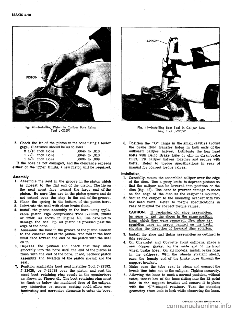
BRAKES 5-28
Fig.
40—Installing Piston in Caliper Bore Using
Tool J-22591
Fig.
41—Installing Boot Seal in Caliper Bore
Using Tool J-22592
5.
Check the fit of the piston in the bore using a feeler
gage.
Clearance should be as follows:
2 1/16 inch Bore .0045 to .010
1 7/8 inch Bore .0045 to .010
1 3/8 inch Bore .0035 to .009
If the bore is not damaged, and the clearance exceeds
either of the upper limits, a new piston will be required.
Assembly
1.
Assemble the seal in the groove in the piston which
is closest to the flat end of the piston. The lip on
the seal must face toward the large end of the
piston. Be sure lips are in the piston groove and do
not extend over the step in the end of the groove.
2.
Place the spring in the bottom of the piston bore.
3.
Lubricate the seal with dean brake fluid.
4.
Install the piston assembly in the bore using appli-
cable piston rign compressor Tool J-22639, 22629
or 22591 as shown in Figure 40. Use care not to
damage the seal lip as piston is pressed past the
edge of the bore. .
5.
Assemble the boot in the groove of the piston closest
to the concave end of the piston. The fold in the boot
must face toward the end of the piston with the seal
on it.
6. Depress the pistons and check that they slide
smoothly into the bore until the end of the piston is
flush with the end of the bore. If not, re check piston
assembly and location of the piston spring and the
seal.
7.
Position applicable boot seal installer Tool J-22592,
J-22628, or J-22638 over the piston and seat the
steel boot retaining ring evenly in the counterbore
as shown in Figure 41. The boot retaining ring must
be flush or below the machined face of the caliper.
Any distortion or uneven seating could allow con-
taminating and corrosive elements to enter the bore.
8. Position the t:O}> rings in the small cavities around
the brake fluid transfer holes in both ends of the
outboard caliper halves. Lubricate the hex head
. bolts with Delco Brake Lube or clip in clean brake
fluid. Fit caliper halves together and secure with
bolts.
Refer to torque specifications in rear of
manual for correct torque valves.
Installation
1.
Carefully mount the assembled caliper over the edge
of the disc. Use a putty knife to depress pistons so
that the caliper can be lowered into position on the
disc (fig. 42). Use care to prevent damage to boots
• on the edge of the disc as the caliper is mounted.
2.
Secure the caliper to the mounting bracket with two
hex head bolts. Refer to torque specifications in
rear of manual for correct torque values.
CAUTION: If replacing old shoe assemblies,
be sure to get the shoes in the same position
from which they were removed. New shoe as-
semblies have an arrow printed on the back,
showing the direction of forward disc rotation.
3.
Install the shoe and lining assemblies as outlined in
this section.
4.
On Chevrolet and Corvette front calipers, place a
new copper gasket on the male end of the front
wheel brake hose. On all models, install brake hose
in the calipers. With the wheels straight ahead,
pass the female end of the brake hose through the
support bracket.
5.
Make sure the tube seat is clean and connect the
break line tube nut to the caliper. Tighten securely.
6. Allowing the hose to seek a normal position, without
twist, insert hex of the hose fitting into the 12-point
hole in the support bracket and secure it in place
with the "V"-shaped retainer. Turn the steering
geometry from lock to lock while observing the hose.
CHEVROLET CHASSIS SERVICE MANUAL
Page 264 of 659
BRAKES
5-31
POWER BRAKES
INDEX
General Description 5-31
Maintenance
and"
Adjustments 5-31
Inspection . ... 5_31
Lubrication 5-31
Bleeding Instructions . . . 5.31
Air Cleaner Service . . . , 5.31
Page
Component Replacement 5-31
Power Brake Cylinder ......* 5-31
Removal . . 5-31
Disassembly and Assembly See Overhaul Manual
Installation . . . . 5-31
GENERAL DESCRIPTION
The Power Brake Unit is a self-contained hydraulic
and vacuum unit, utilizing manifold vacuum and atmos-
phere pressure for its power.
This unit permits the use of a low brake pedal as well
as less pedal effort than is required with the conventional
(nonpower) hydraulic brake system. Only two external
line connections are necessary -
one
a vacuum connection
from manifold to check valve located on front shell; the
other, a hydraulic connection from the main cylinder
outlet directly into the hydraulic system. The unit is
mounted on the engine side of the fire wall and directly
connected to the brake pedal.
MAINTENANCE AND ADJUSTMENTS
INSPECTIONS
1.
Check vacuum line and vacuum line connections as
well as vacuum check valve in front shell of power
unit for possible vacuum loss.
2.
Inspect all hydraulic lines and connections at the
wheel cylinders and main cylinder for possible
hydraulic leaks.
3.
Check brake assemblies for scored drums, grease
or brake fluid on linings, worn or glazed linings,
and make necessary adjustments.
4.
Check brake fluid level in the hydraulic reser-
voirs.
The reservoirs should be filled to the levels
shown in Figure 8.
5. Check for loose mounting bolts at main cylinder and
at power section.
6. Check air cleaner filter in power piston extension
and replace filter if necessary.
7. Check brake pedal for binding and misalignment
between pedal
-and
push rod.
LUBRICATION
The power brake unit is lubricated at assembly and
needs no further lubrication other than maintaining
normal reservoir fluid level. The reservoir should be
filled as described in this section.
BLEEDING INSTRUCTIONS
The power system may be bled manually or with a
pressure bleeder as outlined in this section. Use only
GM
Supreme 11 Brake Fluid or equivalent. Do not use the
power assist while bleeding. The engine should not be
running and the vacuum reserve should be reduced to
zero by applying the brake several times before starting
the bleeding procedure.
AIR CLEANER SERVICE
Servicing of the air cleaner is recommended and the
element replaced when restriction becomes severe
enough to affect power brake response. At any other
time, if cleaning of the filter is felt necessary, it should
be shaken free of dirt or washed in soap and water and
thoroughly dried.
COMPONENT REPLACEMENT
POWER BRAKE CYLINDER
Removal
1.
Remove vacuum hose from vacuum check valve.
2.
Disconnect hydraulic lines at main cylinder.
Disconnect push rod at brake pedal assembly.
Remove nuts and lock washers securing power unit
to fire wall, and remove power unit from engine
compartment.
3.
4.
NOTE:
Chevy
to fire wall.
has a three stud attachment
Repair procedures for the power cylinder are outlined
in the Brake Section of the Overhaul Manual-for service
of the main cylinder refer to applicable portion of
"Standard Brakes" in this manual.
Installation
1.
Mount the power brake assembly in place and install
the attaching nuts and lock washers.
2.
Attach vacuum line to check valve.
3.
Secure hydraulic lines to main cylinder.
4.
Attach push rod to brake pedal assembly, and check
operation of stop light.
5. Bleed brakes as outlined in this section.
CAUTION: After replacing the unit on the vehi-
cle,
start the engine and allow vacuum to build
up before applying the brake.
CHEVROLET CHASSIS SERVICE
Page 266 of 659
SECTION 6
ENGINE
CONTENTS
OF
THIS SECTION
Page
Engine Tune Up
6-1
Torque Sequence
Engine Mechanical
(In
Line)
6-12
Special Tools
. .
Engine Mechanical (V8)
6-24
Page
6-39
6-40
ENGINE TUNE UP
INDEX
Page
General Description
. 6-1
Mechanical Checks and Adjustments
6-1
Spark Plug Removal
6-1
Test Compression
6-1
Service and Install Spark Plugs
6-2
Service Ignition System
6-3
Service Battery
and
Battery Cables
6-5
Service Delcotron
and
Regulator
6-5
Service
Fan
Belt
6-5
Service Manifold Heat Valve
6-5
Tighten Manifold
6-5
Service Fuel Lines
and
Fuel Filter ..........
6-6
Service Cooling System
6-6
Check and Adjust Accelerator Linkage
6-6
Service Crankcase Ventilation
6-6
Service
Air
Injection Reactor System
6-6
Choke Adjustment
6-7
Page
Instrument Cheek-Out
6-7
Instrument Hook-Up.
. 6*7
Check and Adjust Dwell
6-7
Check Dwell Variation
6-7
Check and Adjust Timing
6-8
Adjust Idle Speed
and
Mixture
6-8
Additional Checks and Adjustments
. 6-8
Testing Crankcase Ventilation Valve
. 6-8
Testing Cranking Voltage
6-8
Cylinder Balance Test
. 6-8
Battery
6-8
Ignition
; 6-8
Carburetor
6-11
Fuel Pump
6-11
Cooling System
. 6-11
Cylinder Head Torque and Valve Adjustment
..... 6-11
GENERAL DESCRIPTION
The engine tune up
is
important
to the
modern automo-
tive engine with
its
vastly improved power and perform-
ance.
The
higher compression ratios, improved electri-
cal systems
and
other advances
in
design, make today1 s
engines more sensitive
and
have
a
decided effect
on
power, performance and fuel consumption.
It
is
seldom advisable
to
attempt
a
tune up
by
correc-
tion
of one or two
items only. Time will normally
be
saved
and
more lasting results assured
if the
technician
will follow
a
definite
and
thorough procedure
of
analysis
and correction
of all
items affecting power, performance
and economy.
The tune
up
will
be
performed
in
two parts.
The
first
part will consist
of
visual and mechanical checks and
ad-
justments;
the
second part will consist
of
an instrument
checkout that
can be
performed with
any one of the
units
of service equipment available
for
this purpose. Always
follow
the
instructions provided
by the
manufacturer
of
the particular equipment
to be
used.
Additional checks
and
adjustments
are
included
in the
latter part
of
this section
for use as
required. Many
of
these operations
can be
used
to
isolate and correct trou-
ble located during
the
tune up. Where conditions
are
UB-
covered requiring major corrective action, refer
to the
appropriate section
of
this manual
or the
Passenger
Chassis Overhaul Manual
for
detailed service informa-
tion.
Typical illustrations
and
procedures
are
used except
where specific illustrations
or
procedures
are
necessary
to clarify
the
operation. Illustrations showing bench
op-
erations
are
used
for
clarification however
all
operations
can
be
performed
on the
vehicle.
MECHANICAL CHECKS
AND
ADJUSTMENTS
Spark Plug Removal
Remove any foreign matter from around spark plugs
by
blowing
out
with compressed
air,
then disconnect wires
and remove plugs.
Test Compression
(Fig. 1)
The compression check
is
important because
an
engine
with
low or
uneven compression cannot
be
tuned success-
fully.
It is
essential that improper compression
be cor-
rected before proceeding with
the
engine tune
up.
1.
Remove
air
cleaner
and
block throttle
and
choke
in
wide open position.
2.
Hook
up
starter remote control cable
and
insert
compression gauge firmly
in
spark plug port.
CAUTION: Whenever
the
engine
is
cranked
CHEVROLET
C*
IS SERVICE MANUAL
Page 268 of 659
ENGINE
6-3
(ROUND) Y~~fll^H
CENTRIFUGAL
A ^k
ADVANCE--jflgKpl
MECHANISM
UB|
CAM
KSK^2
LUBRICATOR
VlSMi
REPLACEMENT
^BK
-^ADJUST
SQUARELY
AND
JUST
TOUCHING
LOBE
OF
CAM
/ROTOR
HBB
__
I^BH^F
?
(SOUARE)
^K^ I /—
CAM
jKft^J / LUBRICATOR
H^T^
CAUTION!
QV NEVER
OIL
•L-^
CAM LUBRICATOR-
REPLACE
WICK
WHEN
NECESSARY
LATERAL
MISALIGNMENT
PROPER
LATERAL ALIGNMENT
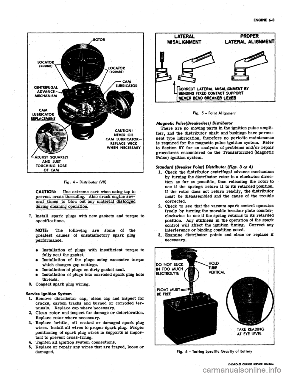
Fig.
4- Distributor (V8)
CAUTION: Use extreme care
-when
using tap to
prevent cross threading. Also crank engine sev-
eral times to blow out any material dislodged
during cleaning operation.
7. Install spark plugs with new gaskets and torque to
specifications.
NOTE:
The following are some of the
greatest causes of unsatisfactory spark plug
performance.
•
Installation of plugs with insufficient torque to
fully seat the gasket.
•
Installation of the plugs using excessive torque
which changes gap settings.
•
Installation of plugs on dirty gasket seal.
•
Installation of plugs into corroded spark plug hole
threads.
8^ Connect spark plug wiring.
Service
Ignition System
1.
Remove distributor cap, clean cap and inspect for
cracks, carbon tracks and burned or corroded ter-
minals. Replace cap where necessary.
2.
Clean rotor and inspect for damage or deterioration.
Replace rotor where necessary.
3.
Replace brittle, oil soaked or damaged spark plug
wires.
Install all wires to proper spark plug. Proper
positioning of spark plug wires in supports is impor-
tant to prevent cross-firing.
4.
Tighten all ignition system connections.
5. Replace or repair any wires that are frayed, loose or
damaged.
Us
CORRECT
LATERAL MISALIGNMENT BY
j BENDING
FIXED CONTACT SUPPORT
[NEVER
BEND BREAKER LEVER
Fig.
5 - Point Alignment
Magnetic
Pulse(Breakerless)
Distributor
There are no moving parts in the ignition pulse ampli-
fier, and the distributor shaft and bushings have perma-
nent type lubrication, therefore no periodic maintenance
is required for the magnetic pulse ignition system. Refer
to Section 6Y for an analysis of problems and/or repair
procedures encountered on the Transistorized (Magnetic
Pulse) ignition system.
Standard
(Breaker Point) Distributor
(Figs.
3 or 4)
1.
Check the distributor centrifugal advance mechanism
by turning the distributor rotor in a clockwise direc-
tion as far as possible, then releasing the rotor to
see if the springs return it to its retarded position.
If the rotor does not return readily, the distributor
must be disassembled and the cause of the trouble
corrected.
2.
Check to see that the vacuum spark control operates
freely by turning the movable breaker plate counter-
clockwise to see if the spring returns to its retarded
position. Any stiffness in the operation of the spark
control will affect the ignition timing. Correct any
interference or binding condition noted.
3.
Examine distributor points and clean or replace if
riecessary.
DO
NOT SUCK
IN
TOO MUCH
ELECTROLYTE
TAKE
READING
AT
EYE LEVEL
Fig.
6 - Testing Specific Gravity of Battery
CHEVROtET
CHASSIS SERVICE MANUAL
Page 269 of 659
ENGINE 6-4
• Contact points with an overall gray color and only
slight roughness or pitting need not be replaced.
• Dirty points should be cleaned with a clean point
file.
Use only a few strokes of a clean, fine-cut con-
tact file. The file should not be used on other
metals and should not be allowed to become
greasy or dirty. Never use emery cloth or sand-
paper to clean contact points since particles will
embed and cause arcing and rapid burning of
points. Do not attempt to remove all roughness
nor dress the point surfaces down smooth.
Merely remove scale or dirt.
• Clean cam lobe with cleaning solvent, lubricate
cam lobe with "Delco Remy Cam and Ball Bearing
Lubricant" or its equivalent and rotate cam lubri-
cator wick 1/2 turn.
• Replace points that are burned or badly pitted.
NOTE: Where prematurely burned or badly
pitted points are encountered, the ignition sys-
tem and engine should be checked to determine
the cause of trouble so it can be eliminated.
Unless the condition causing point burning or
pitting is corrected, new points will provide no .
better service than the old points. Refer to
Section 6Y for an analysis of point burning or
pitting.
• Check point alignment (fig. 5) then, adjust distri-
. butor contact point gap to .019" (new points) or
.016"
(used points). Breaker arm rubbing block
must be on high point of lobe during adjustment.
NOTE: If contact points have been in service,
they should be cleaned with a point file before
adjusting with a feeler gauge.
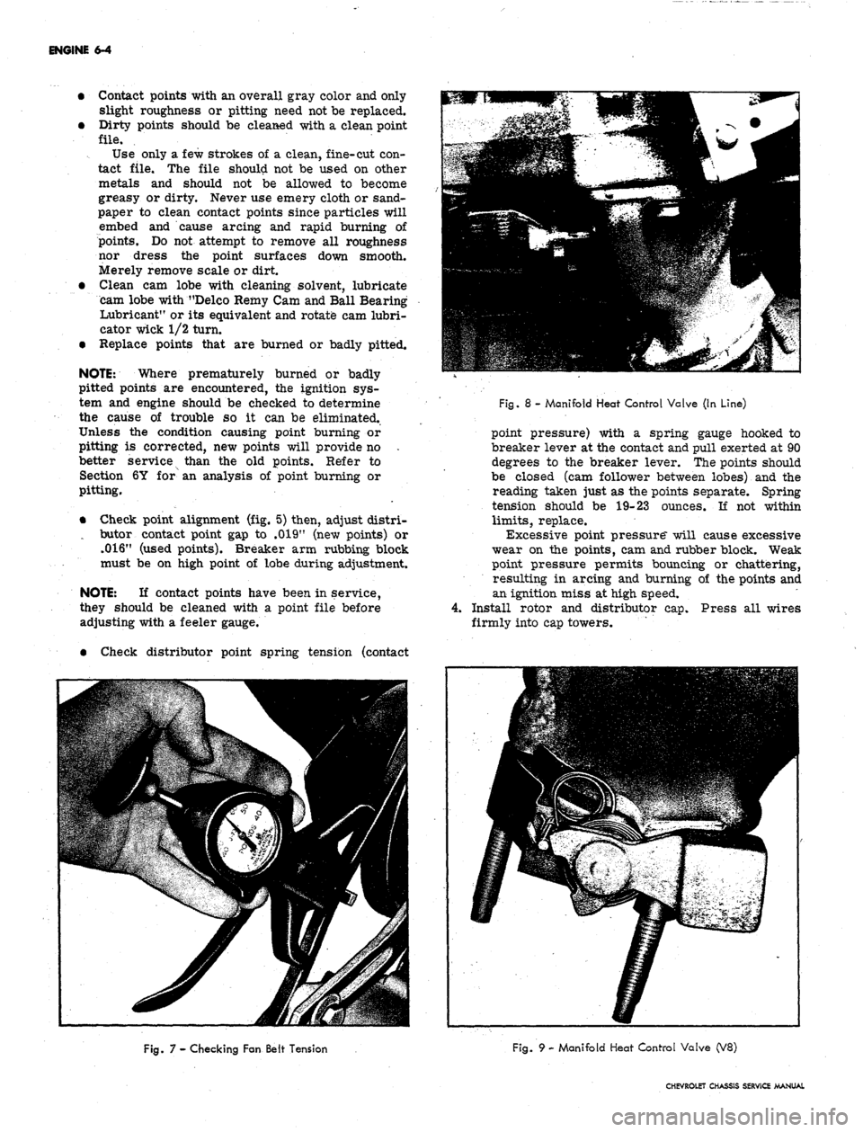
• Check distributor point spring tension (contact
Fig. 8 - Manifold Heat Control Valve (In Line)
point pressure) with a spring gauge hooked to
breaker lever at the contact and pull exerted at 90
degrees to the breaker lever. The points should
be closed (cam follower between lobes) and the
reading taken just as the points separate. Spring
tension should be 19-23 ounces. If not within
limits,
replace.
Excessive point pressure" will cause excessive
wear on the points, cam and rubber block. Weak
point pressure permits bouncing or chattering,
resulting in arcing and burning of the points and
an ignition miss at high speed.
4.
Install rotor and distributor cap. Press all wires
firmly into cap towers.
Fig. 7 - Checking Fan Belt Tension
Fig. 9 - Manifold Heat Control Valve (V8)
CHEVROLET CHASSIS SERVICE MANUAL