lock CHEVROLET CAMARO 1967 1.G Chassis Workshop Manual
[x] Cancel search | Manufacturer: CHEVROLET, Model Year: 1967, Model line: CAMARO, Model: CHEVROLET CAMARO 1967 1.GPages: 659, PDF Size: 114.24 MB
Page 291 of 659
ENGINE 6-26
6. Remove lifting device and lifting adapter then install
rocker arm covers as outlined.
7.
On synchromesh equipped vehicles, install clutch
cross-shaft engine bracket, then adjust and connect
clutch as outlined in Section 7.
8. Connect:
• Speedometer cable.
• Shift linkage at transmission.
• Transmission cooler lines (if so equipped).
9. Install propeller shaft.
10.
Remove jack stands and lower vehicle.
11.
Connect: \ '
Power steering pump lines (if so equipped).
Vacuum line to power brake unit (if so equipped).
Exhaust pipes at manifold flanges.
Accelerator linkage at pedal lever.
Fuel line at fuel pump.
Engine cooler lines (if so equipped).
Oil pressure gauge lines (if so equipped).
12.
Connect wires at:
Coil
Oil pressure switch
Temperature switch
Delcotron
Starter solenoid
13.
Install pulley, fan blade and fan belt as outlined in
Section 6K.
14.
Install radiator and shroud as outlined in Section 13.
15.
Install and adjust hood as outlined in Section 11.
16.
Connect battery cables.
17.
Fill with coolant, engine oil and transmission oil,
then start engine and check for leaks.
18.
Perform necessary adjustments and install air
cleaner.
INTAKE MANIFOLD
Removal
1.
Drain radiator and remove air cleaner.
2.
Disconnect:
Battery cables at battery.
Upper radiator and heater hose at manifold.
Accelerator linkage at pedal lever.
Fuel line at carburetor. ;
Wires at temperature sending switch and coil
(both sides).
Power brake hose at carburetor base.
Spark advance hose at distributor.
Crankcase ventilation hoses (as required).
3.
Remove distributor cap and mark rotor position with
chalk. Remove distributor clamp and distributor,
then position distributor cap rearward clear of
manifold.
4.
Remove coil.
5.
Remove manifold-to-head attaching bolts, then re^
move manifold, (with carburetor on) from engine and
discard gaskets and seals.
6. If manifold is to be replaced,,transfer:
Carburetor and carburetor mounting studs.
Temperature sending switch.
Water outlet and thermostat (use new gasket).
Heater hose adapter.
Choke coil.
Installation
1.
Clean gasket and seal surfaces of manifold, cylinder
heads and block.
2.
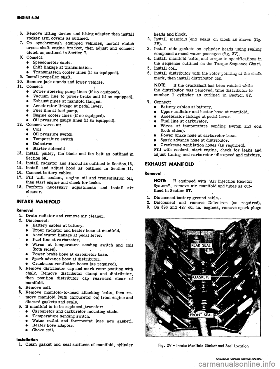
Install manifold end seals on block as shown (fig.
2V).
3.
Install side gaskets on cylinder heads using sealing
compound around water passages (fig. 2V).
4.
Install manifold bolts, and torque to specifications in
the sequence outlined on the Torque Sequence Chart.
5.
Install coil.
6. Install distributor with the rotor pointing at the chalk
mark, then install distributor cap.
NOTE:
If the crankshaft has been rotated while
the distributor was removed, time distributor to
number 1 cylinder as outlined in Section 6Y.
7.
Connect:
Battery cables at battery.
Upper radiator and heater hose at manifold.
Accelerator linkage at pedal lever.
Fuel line at carburetor.
Wires at temperature sending switch and coil
(both sides)!
Power brake hose at carburetor base.
Spark advance hose at distributor.
Crankcase ventilation hoses (as required).
Fill with coolant, start engine, check for leaks and
adjust timing and carburetor idle speed and mixture.
EXHAUST MANIFOLD
Removal
NOTE:
If equipped with "Air Injection Reactor
System", remove air manifold and tubes as out-
lined in Section 6T.
1.
Disconnect battery ground cable.
-
2.
Disconnect and remove Delcotron (as required).
3.
On 396 and 427 cu. in. engines, remove spark plugs
Fig. 2V - Intake Manifold Gasket and Seal Location
CHEVROLET CHASSIS SERVICE MANUAL
Page 292 of 659
ENGINE 6-27
and spark plug shields.
4.
Remove exhaust manifold flange nuts, then lower ex-
haust pipe assembly (hang exhaust pipe from frame
with wire).
5.
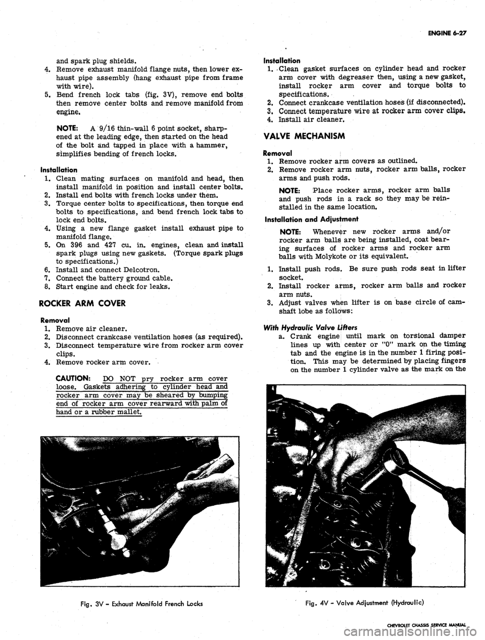
Bend french lock tabs (fig. 3V), remove end bolts
then remove center bolts and remove manifold from
engine.
NOTE: A 9/16 thin-wall 6 point socket, sharp-
ened at the leading edge, then started on the head
of the bolt and tapped in place with a hammer,
simplifies bending of french locks.
Installation
1.
Clean mating surfaces on manifold and head, then
install manifold in position and install center bolts.
2.
Install end bolts with french locks under them.
3.
Torque center bolts to specifications, then torque end
bolts to specifications, and bend french lock tabs to
lock end bolts.
4.
Using a new flange gasket install exhaust pipe to
manifold flange.
5.
On 396 and 427 cu. in. engines, clean and install
spark plugs using new gaskets. (Torque spark plugs
to specifications.)
6. Install and connect Delcotron.
7.
Connect the battery ground cable.
8. Start engine and check for leaks.
ROCKER ARM COVER
Removal
1.
Remove air cleaner.
2.
Disconnect crankcase ventilation hoses (as required).
3.
Disconnect temperature wire from rocker arm cover
clips.
4.
Remove rocker arm cover.
CAUTION: DO NOT pry rocker arm cover
loose. Gaskets adhering to cylinder head and
Installation
1.
.Clean gasket surfaces on cylinder head and rocker
arm cover with degreaser then, using a new gasket,
install rocker arm cover and torque bolts to
specifications. .
2.
Connect crankcase ventilation hoses (if disconnected).
3.
Connect temperature wire at rocker arm cover clips.
4.
Install air cleaner.
VALVE MECHANISM
Removal
1.
Remove rocker arm covers as outlined.
2.
Remove rocker arm nuts, rocker arm balls, rocker
arms and push rods.
NOTE: Place rocker arms, rocker arm balls
and push rods in a rack so they may be rein-
stalled in the same location.
Installation and Adjustment
NOTE: Whenever new rocker arms and/or
rocker arm balls are being installed, coat bear-
ing surfaces of rocker arms and rocker arm
balls with Molykote or its equivalent.
1.
Install push rods; Be sure push rods seat in lifter
socket.
2.
Install rocker arms, rocker arm balls and rocker
arm nuts.
3.
Adjust valves when lifter is on base circle of cam-
shaft lobe as follows:
With Hydraulic Valve
Lifters
2L.
Crank engine until
mark on torsional damper
lines up with center or "0M mark on the timing
tab and the engine is in the number 1 firing posi-
tion. This may be determined by placing fingers
on the number 1 cylinder valve as the mark on the
rocker arm cover may be sheared by bumpii
end of rocker arm cover rearward with palm
hand or a rubber mallet.
Fig.
3V - Exhaust Manifold French Locks
Fig.
4V - Valve Adjustment (Hydraulic)
CHEVROLET CHASSIS SERVICE MANUAL
Page 293 of 659
ENGINE 6-28
damper comes near the "0" mark on the front
cover.
11
the valves are not moving, the engine is
in the number 1 firing position. If the valves
move as the mark comes up to the timing tab, the
.
engine is in number 6 firing position and crank-
shaft should be rotated one more revolution to
reach the number 1 position,
b.
Valve adjustment is made by backing off the ad-
justing nut (rocker arm stud nut) until there is
play in the push rod and then tighten nut to just
remove all push rod to rocker arm clearance.
' this may be determined by rotating push rod with
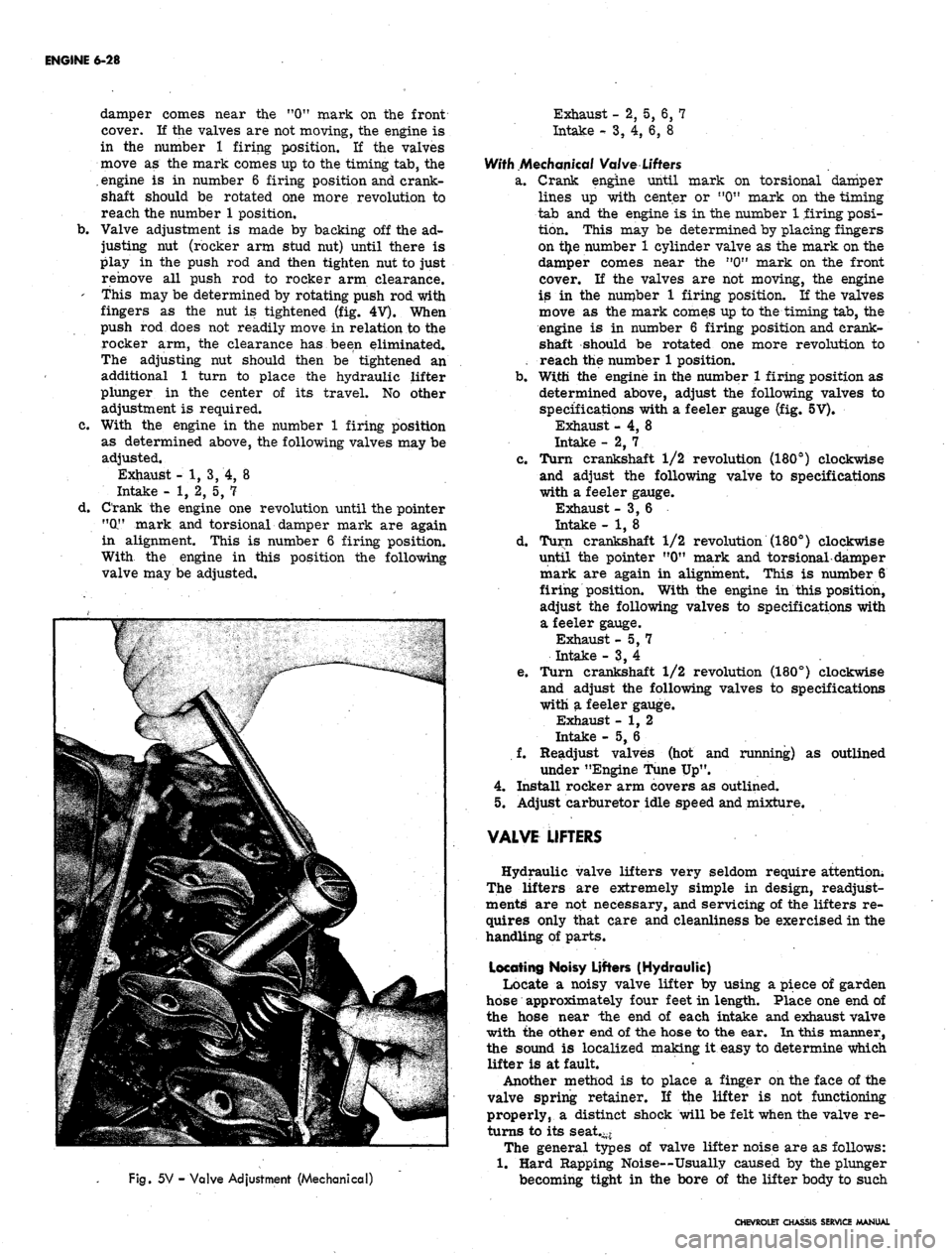
fingers as the nut is tightened (fig. 4
V).
When
push rod does not readily move in relation to the
rocker arm, the clearance has been eliminated.
The adjusting nut should then be tightened an
additional 1 turn to place the hydraulic lifter
plunger in the center of its travel. No other
adjustment is required.
c. With the engine in the number 1 firing position
as determined above, the following valves may be
adjusted.
Exhaust - 1, 3, 4, 8
Intake - 1, 2, 5, 7
d. Crank the engine one revolution until the pointer
"(X" mark and torsional damper mark are again
in alignment. This is number 6 firing position.
With the engine in this position the following
valve may be adjusted.
Fig.
5V - Valve Adjustment (Mechanical)
Exhaust - 2, 5, 6, 7
Intake
-•
3, 4, 6, 8
With Mechanical Valve
Lifters
a. Crank engine until mark on torsional damper
lines up with center or "0" mark on the timing
tab and the engine is in the number 1 firing posi-
tion. This may be determined by placing fingers
on t£e number 1 cylinder valve as the mark on the
damper comes near the n0" mark on the front
cover. If the valves are not moving, the engine
is in the number 1 firing position. If the valves
move as the mark comes up to the timing tab, the
engine is in number 6 firing position and crank-
shaft should be rotated one more revolution to
reach the number 1 position.
b.
With the engine in the number 1 firing position as
determined above, adjust the following valves to
specifications with a feeler gauge (fig. 5V).
Exhaust - 4, 8
Intake - 2, 7. .
c. Turn crankshaft 1/2 revolution (180°) clockwise
and adjust the following valve to specifications
with a feeler gauge.
Exhaust -3,6
Intake - 1, 8
d. Turn crankshaft 1/2 revolution (180°) clockwise
until the pointer "0" mark and torsional-damper
mark are again in alignment. This is number 6
firing position. With the engine in this position,
adjust the following valves to specifications with
a feeler gauge.
Exhaust -5,7
Intake - 3, 4
e. Turn crankshaft 1/2 revolution (180°) clockwise
and adjust the following valves to specifications
with a feeler gauge.
Exhaust - 1, 2
Intake - 5, 6
f. Readjust valves (hot and running) as outlined
under "Engine Tune Up".
4.
Install rocker arm covers as outlined.
5.
Adjust carburetor idle speed and mixture.
VALVE LIFTERS
Hydraulic valve lifters very seldom require attention;
The lifters are extremely simple in design, readjust-
ments are not necessary, and servicing of the lifters re-
quires only that care and cleanliness be exercised in the
handling of parts.
Locating Noisy Lifters (Hydraulic)
Locate a noisy valve lifter by using a piece of garden
hose approximately four feet in length. Place one end of
the hose near the end of each intake and exhaust valve
with the other end of the hose to the ear. In this manner,
the sound is localized making it easy to determine which
lifter is at fault.
Another method is to place a finger on the face of the
valve spring retainer. If the lifter is not functioning
properly, a distinct shock will be felt when the valve re-
turns to its seat.-*
The general types of valve lifter noise are as follows:
1.
Hard Rapping Noise—Usually caused by the plunger
becoming tight in the bore of the lifter body to such
CHEVROLET CHASSIS SERVICE MANUAL
Page 294 of 659
ENGINE 6-29
an extent that the return spring can no longer push
the plunger back up to working position. Probable
causes are:
a. Excessive varnish or carbon deposit causing ab-
normal stickiness.
b.
(Sailing or "pick-up" between plunger and bore of
lifter body, usually caused by an abrasive piece of
dirt or metal wedging between plunger and lifter
body.
2.
Moderate Rapping Noise--Probable causes are:
a. Excessively high leakdown rate.
b.
Leaky check valve seat.
c. Improper adjustment.
3.
General Noise Throughout the Valve Train-rThis
will, in almost all cases, be a definite indication of
insufficient oil supply, or improper adjustment.
4.
Intermittent Clicking—Probable causes are:
a. A microscopic piece of dirt momentarily caught
between ball seat and check valve ball.
b.
In rare cases, the ball itself may be out-of-round
or have a flat spot.
c. Improper adjustment.
In most cases where noise exists in one or more lifters
all lifter units should be removed, disassembled, cleaned
in a solvent, reassembled, and reinstalled in the engine.
If dirt, corrosion, carbon, etc. is shown to exist in one
unit, it more than likely exists in all the units, thus it
would only be a matter of time before all lifters caused
trouble.
Removal
1.
Remove intake manifold as outlined.
2.
Remove valve mechanism as outlined.
3.
Remove valve lifters.
NOTE: Place valve lifters in a rack so they
may be reinstalled in the same location.
Installation
1.
Install valve lifters.
NOTE: Whenever new valve lifters are being
installed coat foot of valve lifters with Molykote
or its equivalent.
2.
Install intake manifold as outlined.
3.
Install and adjust valve mechanism as outlined.
VALVE STEM OIL SEAL AND/OR VALVE SPRING
Replacement
1.
Remove rocker arm cover(s) as outlined.
2.
Remove spark plug, rocker arm and push rod on the
cylinders to be serviced.
3.
Apply compressed air to the spark plug hole to hold
tl*e valves in place.
NOTE: A tool to apply air to the cylinder is
available through local jobbers or may be manu-
factured. In manufacturing this Tool a AC-46N
Spark Plug or its equivalent is recommended.
This will make the Tool universal for all
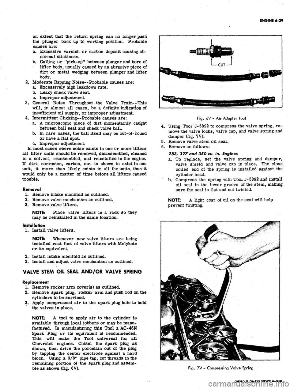
Chevrolet engines. Chisel the spark plug as
shown, then drive the porcelain out of the plug
by tapping the center electrode against a hard
block. Using a 3/8" pipe tap, cut threads in the
remaining portion of the spark plug and assem-
ble as shown (fig. 6V).
Fig.
6V - Air Adapter Tool
4.
Using Tool J-5892, to compress the valve spring, re-
move the valve locks, valve cap, and valve spring and
damper (fig. 7V).
5.
Remove valve stem oil seal.
6. Remove as follows:
283, 327 and 350 eu. in.
Engines
a. To replace, set the valve spring and damper,
valve shield and valve cap in place. The close
coiled end of the spring is installed against the
cylinder head.
b.
Compress the spring with Tool J-5892 and install
oil seal in the lower groove of the stem, making
sure the seal is flat and not twisted.
NOTE: A light coat of oil on the seal will help
prevent twisting.
Fig.
7V - Compressing Valve Spring
CHEVROLET CHASSIS SERVICE MANUAL
Page 295 of 659
ENGINE 6-30
c". Install the valve locks and release the compres-
sor tool making sure the locks seat properly in
the upper groove of the valve stem.
NOTE: Grease may be used to hold the locks
in place while releasing the compressor tool.
396 and 427
cu.
in.
Engines
a. Install new valve stem oil seal (coated with oil)
in position over valve guide.
b.
Set the valve spring and damper and valve cap in
place.
c. Compress the spring with Tool J-5892 and install
the valve locks, then release the compressor tool,
making sure the locks seat properly in the groove
of the valve stem.
NOTE: Grease may be used to hold the locks
in place while releasing the compressor tool.
7.
Install spark ,plug, using a new gasket, and torque to
specifications. -
8. Install and adjust valve mechanism as outlined.
CYLINDER HEAD ASSEMBLY
Removal
1.
Remove intake manifold as outlined.
2.
Remove exhaust manifolds as outlined.
3.
Remove valve mechanism as outlined.
4.
Drain cooling system (block).
5.
Remove cylinder head bolts, cylinder head and gas-
ket. Place cylinder head on two blocks of wood to
prevent damage.
Installation
CAUTION: The gasket surfaces on both the
head and the block must be clean of any foreign
ttter and free of nicks or heavy scratches.
Under bolt threads in the block and threads on
Pie cylinder head bolt must be cleaned. (Dirt
will affect bolt torqueT)
1.
On engines using a STEEL gasket, coat both sides of
a new gasket with a good sealer, spread the sealer
thin and even. One method of applying the sealer that
will assure the proper- coat is with the use of a paint
roller. Too much sealer may hold the beads of the
gasket away from the head or block.
CAUTION: Use no sealer on engines using a
composition STEEL ASBESTOS gasket.
2.
Place the gasket in position over the dowel pins with
the bead up.
3.
Carefully guide cylinder head into place over dowel
pins and gasket.
4.
Coat threads of cylinder head bolts with sealing
compound and install finger tight.
5.
Tighten cylinder head bolts a little at a time in the
sequence shown on the torque sequence chart until
the specified torque is reached.
6. Install the exhaust manifold as outlined.
7.
Install the intake manifold as outlined.
8. Install and adjust the valve mechanism as outlined.
OIL
PAN
Removal
Chevrolet
and Camaro
1.
Disconnect battery positive cable.
2.
Disconnect distributor cap from distributor (to pr-e-
vent breaking distributor cap when engine is raised).
3.
Drain radiator, then disconnect lower radiator hose
at water pump and remove oil dip stick and tube
(where necessary). '
4.
Remove fan blade.
5.
Raise vehicle then drain engine oil;
6. Remove through bolts from engine front mounts.
Disconnect and remove starter.
7.
On vehicles equipped with automatic transmissions,
remove converter housing underpan.
8. Disconnect steering rod at idler lever then swing
steering linkage 4pwn for oil pan clearance.
9. Rotate crankshaft untii timing mark on torsional
damper is at 6:00 o'clock position.
10.
Using a suitable jack, and a block of wood to prevent
damaging oil pan, raise engine "enough to insert 2" x
4"
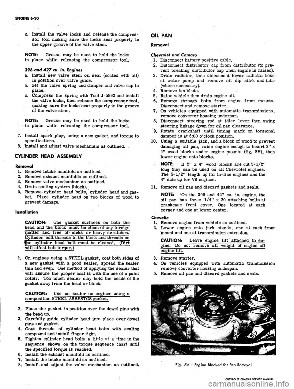
wood blocks under engine mounts (fig. 8V), then
lower engine onto blocks.
NOTE: If 2" x 4" wood blocks are cut 5-1/2"
long they can be used on all Chevrolet engines.
The 5-1/2" length up for In-line engines and the
4"
side up for V8 engines.
11.
Remove oil pan and discard gaskets and seals.
NOTE: -On the 396 and 427 cu. in. engine, the
oil pan has three 1/4" x 20 attaching bolts at ,
crankcase front cover. One located at each
corner and one at lower center.
Chevelle
1.
Remove engine from vehicle as outlined.
2.
Lower engine onto jack stands, one at each front
Tnaount and one at transmission extension.
CAUTION: Leave engine lift attached to en-
gine.
Do not remove all weight of engine off
engine lifET
3.
Remove starter.
4.
On vehicles equipped with automatic transmission
remove converter housing underpan.
5.
Remove oil pan and discard gaskets and seals.
Fig.
8V - Engine Blocked for Pan Removal
CHEVROLET CHASSIS SERVICE MANUAL
Page 296 of 659
ENGINE 6-31
Chevy II
1.
Disconnect battery positive cable.
2.
Drain engine oil.
3.
Disconnect and remove starter.
4 Disconnect steering idler arm bracket at right hand
frame rail and swing steering linkage down for pan
clearance.
5.
Disconnect* exhaust pipes at manifolds and allow
pipes to hang free.
6. Remove oil pan and discard gaskets and seals.
Corvette
1.
Disconnect battery positive cable then remove oil
dipstick and tube.
2.
Raise and support vehicle then drain engine oil.
3.
Remove starter and flywheel underpan.
4.
Disconnect steering linkage idler at frame and lower
the linkage.
5.
Remove oil pan and discard gaskets and seals.
6. On Hi-Performance engines, the oil baffle must
be removed before additional operations can be
performed.
NOTE: On the 427 cu. in. engine, the oil pan
has three 1/4" x 20 attaching bolts at crankcase
front cqver. One located at each corner and one
at lower center.
Installation
1.
Thoroughly clean all gasket sealing surfaces.
NOTE: Use a new pan. gasket set.
2.
Install side gaskets on pan rails, using.gasket sealer
as a retainer.
3.
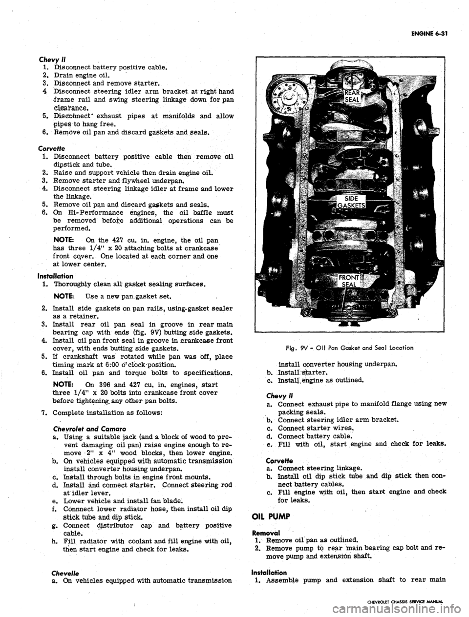
Install rear oil pan seal in groove in rear main
bearing cap with ends (fig. 9V) butting side gaskets.
4.
Install oil pan front seal in groove in .crankcaee front
cover, with ends butting side gaskets.
5.
If crankshaft was rotated while £>an was off, place
timing mark at 6:00 o'clock position.
6. Install oil pan and torque bolts to specifications.
NOTE: On 396 and 427 cu. in. engines, start
three 1/4" x 20 bolts into crankcase front cover
before tightening, any other pan bolts.
7.
Complete installation as follows:
Chevrolet
and Camaro
a. Using a suitable jack (and a block of wood to pre-
vent damaging oil pan) raise engine enough to re-
move 2" x 4" wood blocks, then lower engine.
b.
On vehicles equipped with automatic transmission
install converter housing underpan.
c. Install through bolts in engine front mounts.
d. Install and connect starter. Connect steering rod
at idler lever.
e. Lower vehicle and install fan blade.
f. Cbnnnect lower radiator hose, then install oil dip
stick tube and dip stick.
g. Connect distributor cap and battery positive
cable.
h. Fill radiator with coolant and fill engine with oil,
then start engine and check for leaks.
Chevelle
a. On vehicles equipped with automatic transmission
Fig.
9V - Oil Pan Gasket and Seal Location
install converter housing underpan.
b.
.Install starter.
c. Install, engine as outlined.
Chevy II
a. Connect exhaust pipe to manifold flange using new
packing seals.
b.
Connect steering idler arm bracket.
c. Connect starter wires..
d. Connect battery cable.
e. Fill with oil, start engine and check for leaks.
Corvette
a. Connect steering linkage.
b.
Install oil dip stick tube and dip stick then con-
nect battery cables.
c. Fill engine with oil, then start engine and check
for leaks.
OIL PUMP
Removal
1.
Remove oil pan as outlined.
2.
Remove pump to rear main bearing cap bolt and re-
move pump and extension shaft.
Installation
1.
Assemble pump and extension shaft to rear main
CHEVROLET CHASSIS SERVICE MANUAL
Page 298 of 659
ENGINE 6-33
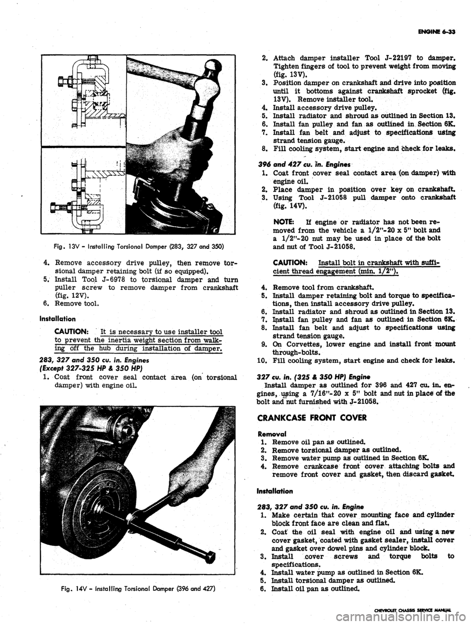
Fig.
13V - Installing TorsionaI Damper (283, 327 and 350)
4.
Remove accessory drive pulley, then remove tor-
sional damper retaining bolt (if so equipped).
5. Install Tool J-6978 to torsional damper and turn
puller screw to remove damper from crankshaft
(fig. 12V).
6. Remove tool.
Installation
CAUTION: It is necessary to use installer tool
to prevent the inertia weight section from walk-
ing off the hub during installation of damper.
283, 327 and 350 cu. in. Engines
(Except 327-325 HP & 350 HP)
1.
Coat front cover seal contact area (on torsional
damper) with engine oil.
Fig.
14V - Installing Torsional Damper (396 and 427)
2.
Attach damper installer Tool J-22197 to damper.
Tighten fingers of tool to prevent weight from moving
(fig. 13V).
3.
Position damper on crankshaft and drive into position
until it bottoms against crankshaft sprocket (fig.
13V).
Remove installer tool.
4.
Install accessory drive pulley.
5. Install radiator and shroud as outlined in Section 13.
6. Install fan pulley and fan as outlined in Section 6K.
7. Install fan belt and adjust to specifications using
strand tension gauge.
8. Fill cooling system, start engine and check for leaks.
396 and 427
cu.
in.
Engines
1.
Coat front cover seal contact area (on damper) with
engine oil.
2.
Place damper in position over key on crankshaft.
3.
Using Tool J-21058 pull damper onto crankshaft
(fig. 14V).
NOTE:
If engine or radiator has not been re-
moved from the vehicle a 1/2"- 20 x 5" bolt and
a
1/2"-20
nut may be used in place of the bolt
and nut of Tool J-21058.
CAUTION: Install bolt in crankshaft with suffi-
cient thread engagement (min. 1/2").
4.
Remove tool from crankshaft.
5. Install damper retaining bolt and torque to specifica-
tions,
then install accessory drive pulley.
6. Install radiator and shroud as outlined in Section 13.
7. Install fan pulley and fan as outlined in Section 6K.
8. Install fan belt and adjust to specifications using
strand tension gauge.
9. On Corvettes, lower engine and install front mount
through-bolts.
10.
Fill cooling system, start engine and check for leaks.
327
cu.
in. (325 & 350 HP)
Engine
Install damper as outlined for 396 and 427 cu. in. en-
gines,
using a 7/16"-20 x 5" bolt and nut in place of the
bolt and nut furnished with J-21058.
CRANKCASE FRONT COVER
Removal
1.
Remove oil pan as outlined.
2.
Remove torsional damper as outlined.
3.
Remove water pump as outlined in Section 6K.
4.
Remove crankcase front cover attaching bolts and
remove front cover and gasket, then discard gasket
Installation
283, 327 and 350 cu. in.
Engine
1.
Make certain that cover mounting face and cylinder
block front face are clean and flat.
2.
Coat the oil seal with engine oil and using a new
cover gasket, coated with gasket sealer, install cover
and gasket over dowel pins and cylinder block.
3.
Install cover screws and torque bolts to
specifications.
4.
Install water pump as outlined in Section 6K.
5. Install torsional damper as outlined.
6. Install oil pan as outlined.
CHEVROLET CHASSIS SOVKZ MANUAL
Page 299 of 659
ENGINE 6-34
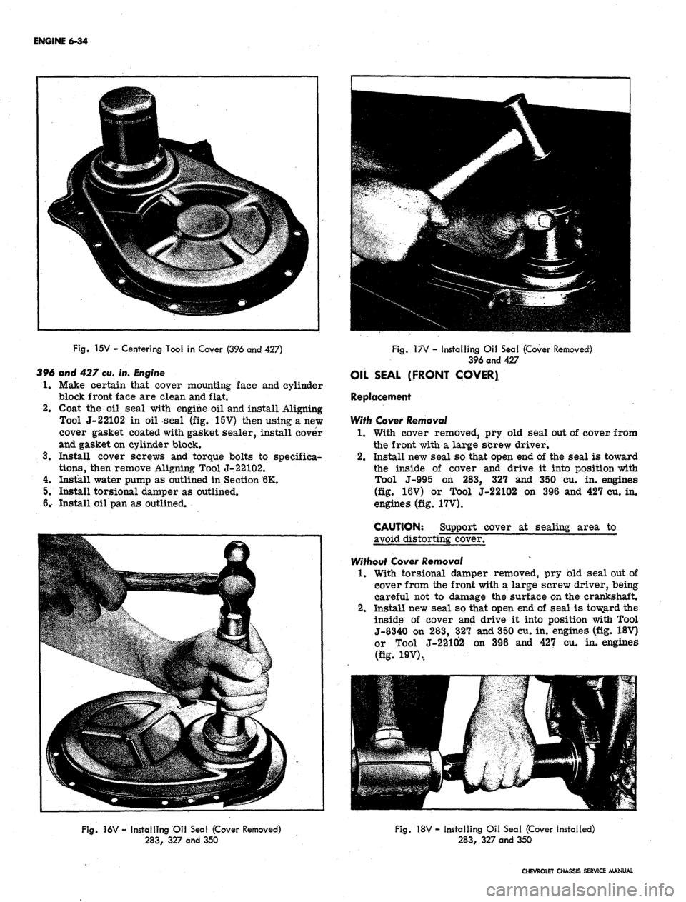
Fig.
15V - Centering Tool in Cover (396 and 427)
396 and 427
cu.
in.
Engine
1.
Make certain that cover mounting face and cylinder
block front face are clean and flat.
2.
Coat the oil seal with engine oil and install Aligning
Tool J-22102 in oil seal (fig. 15V) then using a new
cover gasket coated with gasket sealer, install cover
and gasket on cylinder block.
3.
Install cover screws and torque bolts to specifica-
tions,
then remove Aligning Tool J-22102.
4.
Install water pump as outlined in Section 6K.
5. Install torsional damper as outlined.
6. Install oil pan as outlined.
Fig.
17V - Installing Oil Seal (Cover Removed)
396 and 427
OIL SEAL (FRONT COVER)
Replacement
With Cover
Removal
1.
With cover removed, pry old seal out of cover from
the front with a large screw driver.
2.
Install new seal so that open end of the seal is toward
the inside of cover and drive it into position with
Tool J-995 on 283, 327 and 350 cu. in. engines
(fig. 16V) or Tool J-22102 on 396 and 427 cu. in.
engines (fig. 17V).
CAUTION: Support cover at sealing area to
avoid distorting cover.
Without Cover
Removal
1.
With torsional damper removed, pry old seal out of
cover from the front with a large screw driver, being
careful not to damage the surface on the crankshaft.
2.
Install new seal so that open end of seal is toward the
inside of cover and drive it into position with Tool
J-8340 on 283, 327 and 350 cu. in. engines (fig. 18V)
or Tool J-22102 on 396 and 427 cu. in. engines
(fig. 19V),
Fig.
16V - Installing Oil Seal (Cover Removed)
283,
327 and 350
Fig.
18V- Installing Oil Sea! (Cover Installed)
283,
327 and 350
CHEVROLET CHASSIS SERVICE MANUAL
Page 306 of 659
SECTION 6K
ENGINE COOLING
INDEX
Page
General Description . . . 6K-1
Maintenance and Adjustments 6K-1
Coolant Level 6K-1
Coolant System Checks 6K-1
Periodic Maintenance 6K-2
Cleaning 6K-2
Reverse Flushing 6K-2
Radiator 6K-2
Page
Cylinder Block and Cylinder Head 6K-2
Hot Water Heater 6K-2
Fan Belt . 6K-2
Adjustment ....". 6K-2
Thermostat . 6K-2
Replacement 6K-2
Water Pump. . . . 6K-3
Removal 6K-3
Installation 6K-3
GENERAL DESCRIPTION
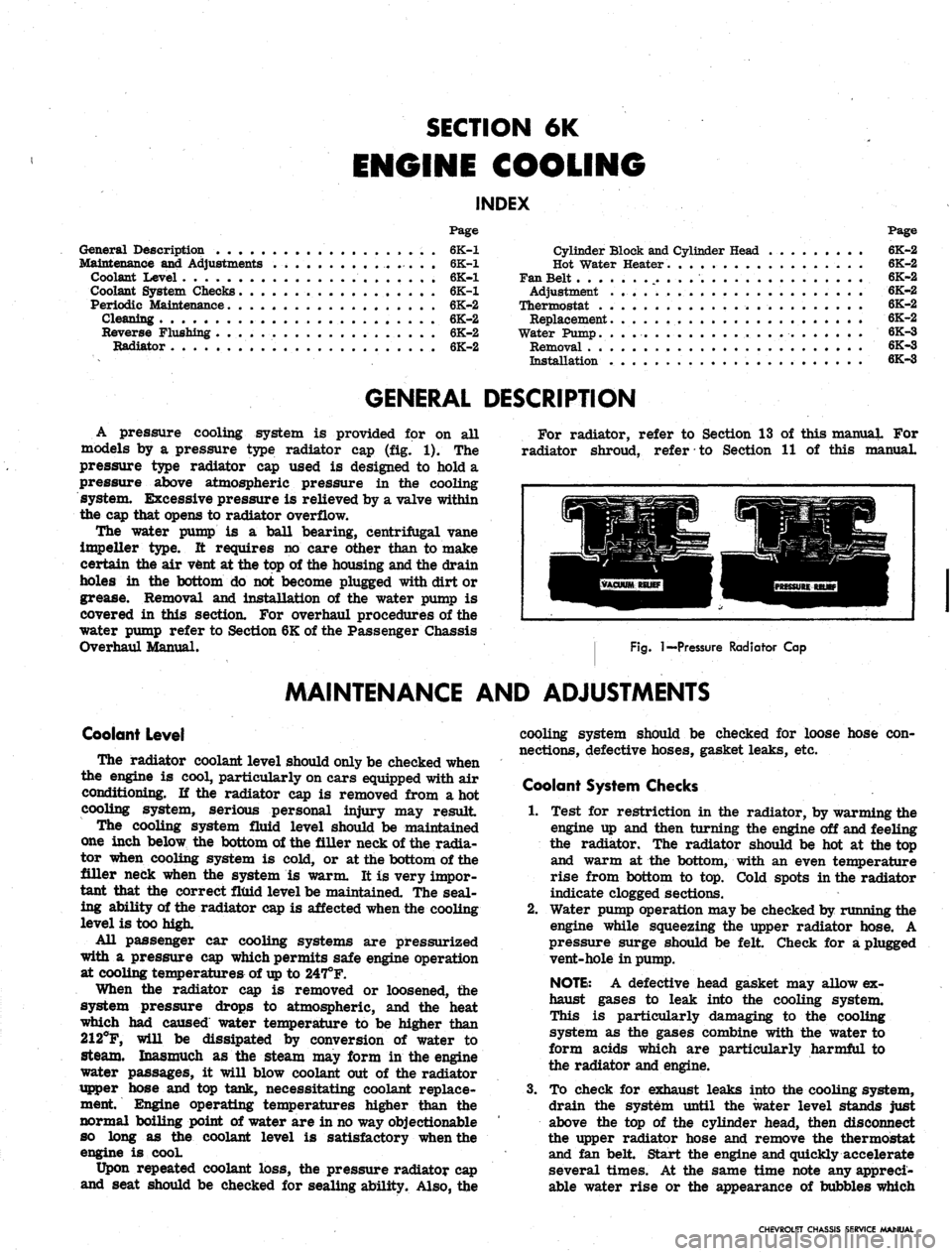
A pressure cooling system is provided for on all
models by a pressure type radiator cap (fig. 1). The
pressure type radiator cap used is designed to hold a
pressure above atmospheric pressure in the cooling
system. Excessive pressure is relieved by a valve within
the cap that opens to radiator overflow.
The water pump is a ball bearing, centrifugal vane
impeller type. It requires no care other than to make
certain the air vent at the top of the housing and the drain
holes in the bottom do not become plugged with dirt or
grease. Removal and installation of the water pump is
covered in this section. For overhaul procedures of the
water pump refer to Section 6K of the Passenger Chassis
Overhaul Manual.
For radiator, refer to Section 13 of this manual For
radiator shroud, refer to Section 11 of this manual.
Fig.
I—Pressure Radiator Cap
MAINTENANCE AND ADJUSTMENTS
Coolant Level
The radiator coolant level should only be checked when
the engine is cool, particularly on cars equipped with air
conditioning. If the radiator cap is removed from a hot
cooling system, serious personal injury may result
The cooling system fluid level should be maintained
one inch below the bottom of the filler neck of the radia-
tor when cooling system is cold, or at the bottom of the
filler neck when the system is warm. It is very impor-
tant that the correct fluid level be maintained. The seal-
ing ability of the radiator cap is affected when the cooling
level is too high.
All passenger car cooling systems are pressurized
with a pressure cap which permits safe engine operation
at cooling temperatures of
up
to 247°F.
When the radiator cap is removed or loosened, the
system pressure drops to atmospheric, and the heat
which had caused water temperature to be higher than
212°F, will be dissipated by conversion of water to
steam. Inasmuch as the steam may form in the engine
water passages, it will blow coolant out of the radiator
upper hose and top tank, necessitating coolant replace-
ment Engine operating temperatures higher than the
normal boiling point of water are in no way objectionable
so long as the coolant level is satisfactory when the
engine is cooL
Upon repeated coolant loss, the pressure radiator cap
and seat should be checked for sealing ability. Also, the
cooling system should be checked for loose hose con-
nections, defective hoses, gasket leaks, etc.
Coolant System Checks
1.
Test for restriction in the radiator, by warming the
engine up and then turning the engine off and feeling
the radiator. The radiator should be hot at the top
and warm at the bottom, with an even temperature
rise from bottom to top. Cold spots in the radiator
indicate clogged sections.
2.
Water pump operation may be checked by running the
engine while squeezing the upper radiator hose. A
pressure surge should be felt Check for a plugged
vent-hole in pump.
NOTE:
A defective head gasket may allow ex-
haust gases to leak into the cooling system.
This is particularly damaging to the cooling
system as the gases combine with the water to
form acids which are particularly harmful to
the radiator and engine.
3.
To check for exhaust leaks into the cooling system,
drain the system until the water level stands just
above the top of the cylinder head, then disconnect
the upper radiator hose and remove the thermostat
and fan belt. Start the engine and quickly accelerate
several times. At the same time note any appreci-
able water rise or the appearance of bubbles which
CHEVROLET CHASSIS SERVICE MANUAL
Page 307 of 659

ENGINE COOLING 6K-2
are indicative of exhaust gases leaking into the coolr
ing system.
Periodic Maintenance
Periodic service must be performed to the engine cool-
ing system to keep it in efficient operating condition.
These services should include a complete cleaning and
reverse flushing as well as a reconditioning service.
In the course of engine operation, rust and scale ac-
cumulate in the radiator and engine water jacket. The
accumulation of these deposits can be kept to a minimum
by the use of a good rust inhibitor but it should be
remembered that an inhibitor will not remove rust al-
ready present in the cooling system.
Two common causes of corrosion are: (1) air suction--
Air may be drawn into the system due to low liquid level
in the radiator, leaky water pump or loose hose con-
nections; (2) exhaust gas leakage—Exhaust gas may be
blown into the cooling system past the cylinder head
gasket or through cracks in the cylinder head and block.
Cleaning
A good cleaning solution should be used to loosen the
rust and scale before reverse flushing the cooling
system. There are a number of cleaning solutions avail-
able and the manufacturer's instructions with the particu-
lar cleaner being used should always be followed.
An excellent preparation to use for this purpose is GM
Cooling System Cleaner. The following directions for
cleaning the system applies only when this type cleaner
is-used.
1.
Drain the cooling system including the cylinder block
and then close both drain plugs.
2.
Remove thermostat and replace thermostat housing.
3.
Add the liquid portion (No. 1) of the cooling system
cleaner.
4.
Fill the cooling system with water to a level of about
3 inches below the top of the overflow pipe.
5. Cover the radiator and run the engine at moderate
speed until engine coolant temperature reaches 180
degrees.
6. Remove cover from radiator and continue to run the
engine for 20 minutes. Avoid boiling.
7. While the engine is still running, add the powder
portion (No. 2) of the cooling system cleaner and
continue to run the engine for 10 minutes.
8. At the end of this time, stop the engine, wait a few
minutes and then open the drain cocks or remove
pipe plugs. Also remove lower hose connection.
CAUTION: Be careful not to scald your hands.
NOTE:
Dirt and bugs may be cleaned out of
the radiator air passages by blowing out with air
pressure from the back of the core.
Reverse Flushing
Reverse flushing should always be accomplished after
the system is thoroughly cleaned as outlined above.
Flushing is. accomplished through the system in a direc-
tion opposite to the normal flow. This action causes the
water to get behind the corrosion deposits and force
them out.
Radiator
1.
Remove the upper and lower radiator hoses and re-
place the radiator cap,
2.
Attach a lead-away hose at the top of the radiator.
3.
Attach a new piece of hose to the radiator outlet
connection and insert the flushing gun in this hose.
4.
Connect the water hose of the flushing gun to a water
outlet and the air hose to an air line.
5. Turn on the water and when the radiator is full, turn
on the air in short blasts, allowing the radiator to
fill between blasts of air.
CAUTION: Apply air gradually as a clogged
radiator will stand only a limited pressure.
6. Continue this flushing until the water from the lead-
away hose runs clear.
Cylinder Block and Cylinder Head
1.
With the thermostat removed, attach a lead-away
hose to the water pump inlet and a length of new hose
to the water outlet connection at the top of the engine.
NOTE:
Disconnect the heater hose when re-
verse flushing engine.
2.
Insert the flushing gun in the new hose.
3.
Turn on the water and when the engine water jacket
is full, turn on the air in short blasts.
4.
Continue this flushing until the water from the lead-
away hose runs clear.
Hot Water Heater
1.
Remove water outlet hose from heater core pipe.
2.
Remove inlet hose from engine connection.
3.
Insert flushing gun and flush heater core. Care must
be taken when applying air pressure to prevent
damage to the core.
Fan Belt
Adjustment
1.
Loosen bolts at Delcotron slotted bracket.
2.
Pull Delcotron away from engine until desired ten-
sion reading is obtained with a strand tension gauge.
Refer to Section 6, "Engine Tune-Up".
3.
Tighten all Delcotron bolts securely.
Thermostat
The thermostat consists of a restriction valve actuated
by a thermostatic element. This is mounted in the hous-
ing at the cylinder head water outlet above the water
pump,
thermostats are designed to open and close at
predetermined temperatures and if not operating properly
should be removed and tested as follows.
Replacement
1.
Remove radiator to water outlet hose.
2.
Remove thermostat housing bolts and remove water
outlet and gasket from thermostat housing (fig. 2).
3.
Inspect thermostat valve to make sure it is in good
condition.
4.
Place thermostat in hot water 25° above the temper-
ature stamped on the thermostat valve.
5. Submerge the valve completely and agitate the water
thoroughly. Under this condition the valve should
open fully.
6. Remove the thermostat and place in water 10° below
temperature indicated on the valve.
7. With valve completely submerged and water agitated
thoroughly, the valve should close completely.
8. If thermostat checks satisfactorily, re-install, using
a new housing gasket.
9. Refill cooling system.
CHEVROLET CHASSIS SERVICE MANUAL