lock CHEVROLET CAMARO 1967 1.G Chassis Manual PDF
[x] Cancel search | Manufacturer: CHEVROLET, Model Year: 1967, Model line: CAMARO, Model: CHEVROLET CAMARO 1967 1.GPages: 659, PDF Size: 114.24 MB
Page 186 of 659
FRONT SUSPENSION
3-22
CHEVROLET
s-L 1 \
TYPICAL
OF
-^-x ^K CORVETTE, CHEVELLE AND CAMARO
CHEVY n
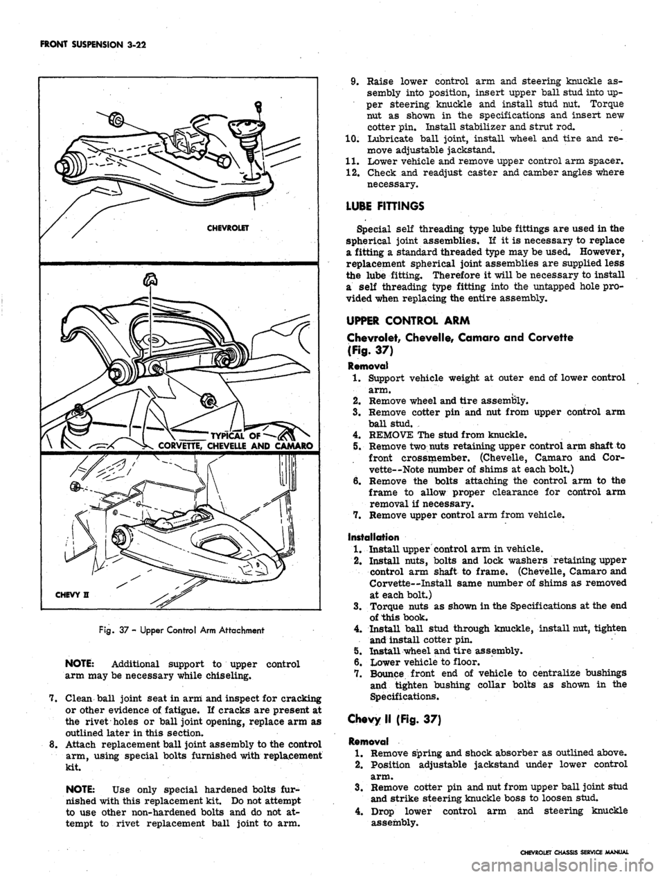
Rg.
37 - Upper Control Arm Attachment
NOTE:
Additional support to upper control
arm may be necessary while chiseling.
7. Clean ball joint seat in arm and inspect for cracking
or other evidence of fatigue. If cracks are present at
the rivet holes or ball joint opening, replace arm as
outlined later in this section.
8. Attach replacement ball joint assembly to the control
arm, using special bolts furnished with replacement
kit.
NOTE:
Use only special hardened bolts fur-
nished with this replacement kit. Do not attempt
to use other non-hardened bolts and do not at-
tempt to rivet replacement ball joint to arm.
9. Raise lower control arm and steering knuckle as-
sembly into position, insert upper ball stud into up-
per steering knuckle and install stud nut. Torque
nut as shown in the specifications and insert new
cotter pin. Install stabilizer and strut rod.
10.
Lubricate ball joint, install wheel and tire and re-
move adjustable jackstand.
11.
Lower vehicle and remove upper control arm spacer.
12.
Check and readjust caster and camber angles where
necessary.
LUBE FITTINGS
Special self threading type lube fittings are used in the
spherical joint assemblies. If it is necessary to replace
a fitting a standard threaded type may be used. However,
replacement spherical joint assemblies are supplied less
the lube fitting. Therefore it will be necessary to install
a self threading type fitting into the untapped hole pro-
vided when replacing the entire assembly.
UPPER CONTROL ARM
Chevrolet, Chevelle, Camaro and Corvette
(Fig.
37)
Removal
1.
Support vehicle weight at outer end of lower control
arm.
2.
Remove wheel and tire assembly.
3.
Remove cotter pin and nut from upper control arm
ball stud. ,
4.
REMOVE The stud from knuckle.
5. Remove two nuts retaining upper control arm shaft to
front crossmember. (Chevelle, Camaro and Cor-
vette—Note number of shims at each bolt.)
6. Remove the bolts attaching the control arm to the
frame to allow proper clearance for control arm
removal if necessary.
7. Remove upper control arm from vehicle.
Installation
1.
Install upper control arm in vehicle.
2.
Install nuts, bolts and lock washers retaining upper
control arm shaft to frame. (Chevelle, Camaro and
Corvette—Install same number of shims as removed
at each bolt.)
3.
Torque nuts as shown in the Specifications at the end
of this book.
4.
Install ball stud through knuckle, install nut, tighten
and install cotter pin.
5. Install wheel and tire assembly.
6. Lower vehicle to floor.
7. Bounce front end of vehicle to centralize bushings
and tighten bushing collar bolts as shown in the
Specifications.
Chevy II (Fig. 37)
Removal
1.
Remove spring and shock absorber as outlined above.
2.
Position adjustable jackstand under lower control
arm.
3.
Remove cotter pin and nut from upper ball joint stud
and strike steering knuckle boss to loosen stud.
4.
Drop lower control arm and steering knuckle
assembly.
CHEVROLET CHASSIS SERVICE MANUAL
Page 187 of 659
FRONT SUSPENSION 3-23
CHEVROLET
J-7052-2
CAMARO
& CHEVELLE
J-21482
CHEVROLET
J-7052-2
CAMARO
& CHEVELLE
J-21482
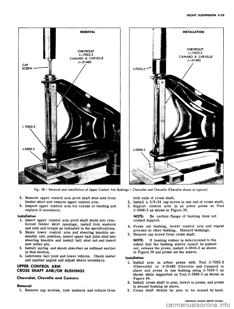
Fig.
38 - Removal and Installation of Upper Control Arm Bushings - Chevrolet and Chevelle (Chevelle shown as typical)
5.
Remove upper control arm pivot shaft stud nuts from
fender skirt and remove upper control arm.
6. Inspect upper control arm for cracks or bending and
replace if necessary.
Installation
1.
Insert upper control arm pivot shaft studs into rein-
forced fender skirt openings, install lock washers
and nuts and torque as indicated in the specifications.
Raise lower control arm and steering knuckle as-
sembly into position, insert upper ball joint stud into
steering knuckle and install ball stud nut and insert
new cotter pin.
Install spring and shock absorber as outlined earlier
in this section.
Lubricate ball joint and lower vehicle. Check caster
and camber angles and adjust where necessary.
UPPER CONTROL ARM
CROSS SHAFT AND/OR BUSHINGS
Chevrolet, Chevelle and Camaro
Removal
1.
Remove cap screws, lock washers and collars from
2.
3.
4.
both ends of cross shaft.
2.
Install a 3/8-24 cap screw in one end of cross shaft,
3.
Support control arm in an arbor press on Tool
J-5888-3 as shown in Figure 38.
NOTE: Be certain flange of bushing does not
contact support.
4.
Press out bushing, invert control arm and repeat
process on other bushing. Discard bushings.
5.
Remove cap screw from cross shaft.
NOTE: If bushing rubber is deteriorated to the
extent that the bushing sleeve cannot be pushed
out, release the press, install J-9502-3 as shown
in Figure 38 and press out the sleeve.
Installation
1.
Install arm in arbor press with Tool J-7052-2
(Chevrolet) or J-21482 (Chevelle and Camaro) in
place and press in one bushing using J-7052-5 as
shown while supported on Tool j-5888-3 as shown in
Figure 38.
2.
Install cross shaft in arm, invert in press, and press
in second bushing as above.
3.
Cross shaft should be able to be turned by hand.
CHEVROLET CHASSIS SERVICE MANUAL
Page 188 of 659
FRONT SUSPENSION 3-24
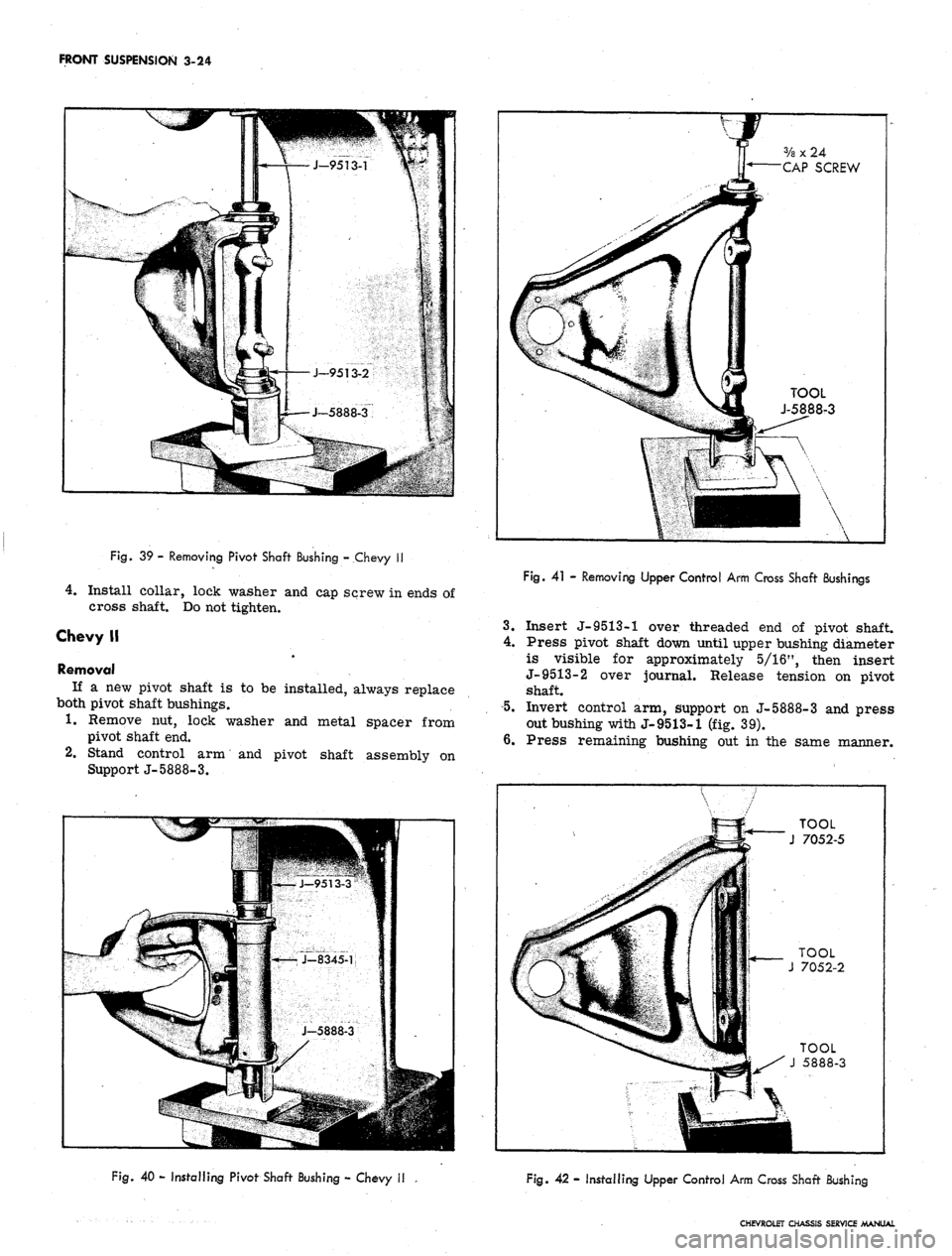
Fig.
39 - Removing Pivot Shaft Bushing - Chevy II
4.
Install collar, lock washer and cap screw in ends of
cross shaft. Do not tighten.
Chevy II
Removal
If a new pivot shaft is to be installed, always replace
both pivot shaft bushings.
1.
Remove nut, lock washer and metal spacer from
pivot shaft end.
2.
Stand control arm and pivot shaft assembly on
Support J-5888-3.
V
f
ff 3/a x 24
y* CAP SCREW
k
a
4f TOOL
i J-5888-3
••
Fig.
41 - Removing Upper Control Arm Cross Shaft Bushings
3.
Insert J-9513-1 over threaded end of pivot shaft.
4.
Press pivot shaft down until upper bushing diameter
is visible for approximately 5/16", then insert
J-9513-2 over journal. Release tension on pivot
shaft.
5.
Invert control arm, support on J-5888-3 and press
out bushing with J-9513-1 (fig. 39).
6. Press remaining bushing out in the same manner.
TOOL
J 7052-5
Fig.
40 - Installing Pivot Shaft Bushing - Chevy II
Fig. 42 - Installing Upper Control Arm Cross Shaft Bushing
CHEVROLET CHASSIS SERVICE MANUAL
Page 189 of 659
FRONT SUSPENSION 3-25
Installation
1.
Insert new bushing in control arm and over pivot
shaft.
2.
Support arm on J-5888-3 and insert Spacer J-
8345-1.
5.
Press bushing into place with Installer J-9513-3
(fig. 40).
Invert arm and press remaining bushing in place with
J-9513-3.
Install bushing spacers, lock washers and nuts
to pivot shaft ends. Torque as indicated in
Specifications.
NOTE:
Pivot shaft bolts must be in horizontal
position (toward center line of vehicle) before
torquing nuts.
Corvette
Removal
1.
Remove cap screws, lock washers and collars from
both ends of cross shaft.
2.
Install a 3/8-24 cap screw (furnished with Tool
J- 5888) in one end of cross shaft.
3.
Support control arm in an arbor press on Tool
J-5888-3 as shown in Figure 41.
NOTE:
Be certain flange of bushing does not
contact support.
4.
Press out bushing, invert control arm and repeat
process on other bushing. Discard bushings.
5. Remove cap screw from cross shaft.
Installation
1.
Install arm in arbor press with Tool J-7052-2 in
place and press in one bushing while supported on
Tool J-5888-3 as shown in Figure 42.
2.
Install cross shaft in arm, invert in press, and press
in second bushing as above.
3.
Cross shaft should be able to be turned by hand.
4.
Install collar, lock washer and cap screw in ends of
cross shaft. Do not tighten.
CHEVROLET CHASSIS SERVICE MANUAL
Page 196 of 659
REAR SUSPENSION AND DRIVE LINE 4-6
Fig.
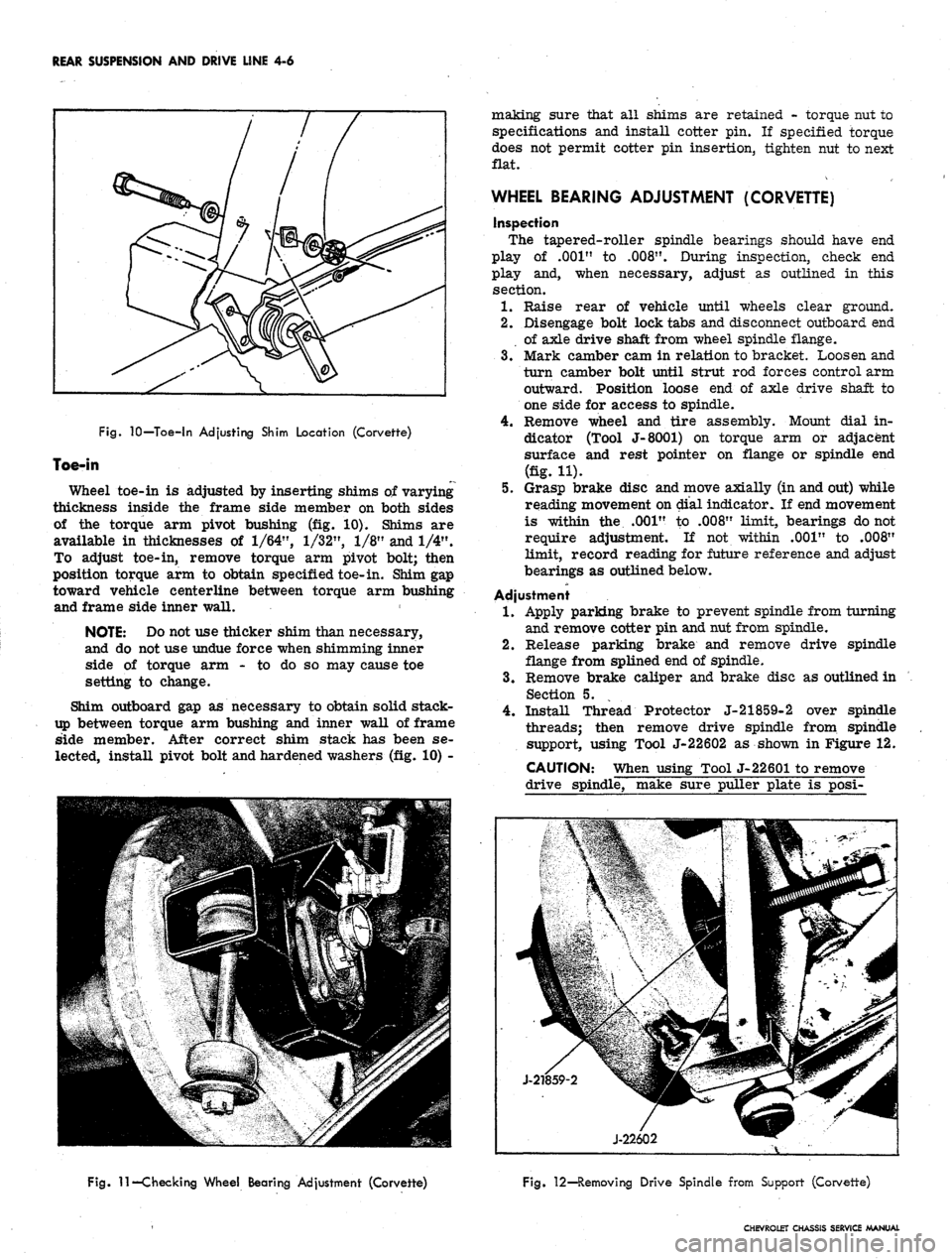
10—Toe-in Adjusting Shim Location (Corvette)
Toe-in
Wheel toe-in is adjusted by inserting shims of varying
thickness inside the frame side member on both sides
of the torque arm pivot bushing (fig. 10). Shims are
available in thicknesses of
1/64",
1/32",
1/8" and 1/4".
To adjust toe-in, remove torque arm pivot bolt; then
position torque arm to obtain specified toe-in. Shim gap
toward vehicle centerline between torque arm bushing
and frame side inner wall.
NOTE: Do not use thicker shim than necessary,
and do not use undue force when shimming inner
side of torque arm - to do so may cause toe
setting to change.
Shim outboard gap as necessary to obtain solid stack-
up between torque arm bushing and inner wall of frame
side member. After correct shim stack has been se-
lected, install pivot bolt and hardened washers (fig. 10) -
making sure that all shims are retained - torque nut to
specifications and install cotter pin. If specified torque
does not permit cotter pin insertion, tighten nut to next
flat.
WHEEL BEARING ADJUSTMENT (CORVETTE)
inspection
The tapered-roller spindle bearings should have end
play of .001" to
.008".
During inspection, check end
play and, when necessary, adjust as outlined in this
section.
1.
Raise rear of vehicle until wheels clear ground.
2.
Disengage bolt lock tabs and disconnect outboard end
of axle drive shaft from wheel spindle flange.
3.
Mark camber cam in relation to bracket. Loosen and
turn camber bolt until strut rod forces control arm
outward. Position loose end of axle drive shaft to
one side for access to spindle.
4.
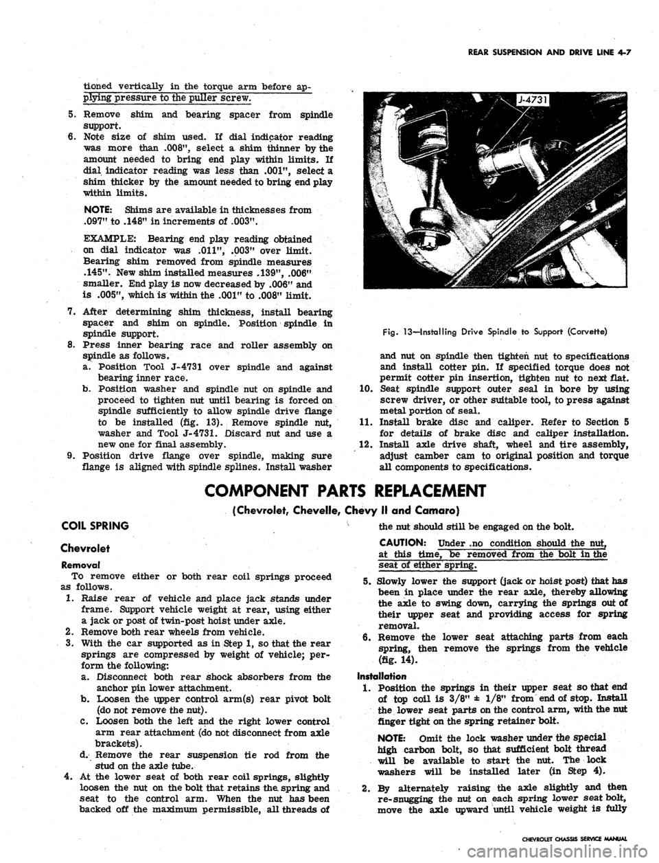
Remove wheel and tire assembly. Mount dial in-
dicator (Tool J-8001) on torque arm or adjacent
surface and rest pointer on flange or spindle end
(fig. H).
5.
Grasp brake disc and move axially (in and out) while
reading movement on dial indicator. If end movement
is within the .001" to .008" limit, bearings do not
require adjustment. If not within .001" to .008"
limit, record reading for future reference and adjust
bearings as outlined below.
Adjustment
1.
Apply parking brake to prevent spindle from turning
and remove cotter pin and nut from spindle.
2.
Release parking brake and remove drive spindle
flange from splined end of spindle.
3.
Remove brake caliper and brake disc as outlined in
Section 5.
4.
Install Thread Protector J-21859-2 over spindle
threads; then remove drive spindle from spindle
support, using Tool J-22602 as shown in Figure 12.
CAUTION: When using Tool J-22601 to remove
drive spindle, make sure puller plate is posi-
Fig.
11—Checking Wheel Bearing Adjustment (Corvette)
Fig. 12—Removing Drive Spindle from Support (Corvette)
CHEVROLET CHASSIS SERVICE MANUAL
Page 197 of 659
REAR SUSPENSION AND DRIVE LINE 4-7
tioned vertically in the torque arm before ap-
plying pressure to the puller screw.
5.
Remove shim and bearing spacer from spindle
support.
6. Note size of shim used. If dial indicator reading
was more than
.008",
select a shim thinner by the
amount needed to bring end play within limits. If
dial indicator reading was less than
.001",
select a
shim thicker by the amount needed to bring end play
within limits.
NOTE: Shims are available in thicknesses from
.097"
to .148" in increments of
.003".
EXAMPLE: Bearing end play reading obtained
on dial indicator was
.011",
.003" over limit.
Bearing shim removed from spindle measures
.145".
New shim installed measures .139", .006"
smaller. End play is now decreased by .006" and
is
.005",
which is within the .001" to .008" limit.
7.
After determining shim thickness, install bearing
spacer and shim on spindle. Position spindle in
spindle support.
8. Press inner bearing race and roller assembly on
spindle as follows.
a. Position Tool J-4731 over spindle and against
bearing inner race.
b.
Position washer and spindle nut on spindle and
proceed to tighten nut until bearing is forced on
spindle sufficiently to allow spindle drive flange
to be installed (fig. 13). Remove spindle nut,
washer and Tool
J-4731.
Discard nut and use a
new one for final assembly.
9. Position drive flange over spindle, making sure
flange is aligned with spindle splines. Install washer
Fig.
13—Installing Drive Spindle to Support (Corvette)
and nut on spindle then tighten nut to specifications
and install cotter pin. If specified torque does not
permit cotter pin insertion, tighten nut to next flat.
10.
Seat spindle support outer seal in bore by using
screw driver, or other suitable tool, to press against
metal portion of seal.
11.
Install brake disc and caliper. Refer to Section 5
for details of brake disc and caliper installation.
12.
Install axle drive shaft, wheel and tire assembly,
adjust camber cam to original position and torque
all components to specifications.
COMPONENT PARTS REPLACEMENT
(Chevrolet, Chevelle, Chevy II and Camaro)
COIL SPRING
Chevrolet
Removal
To remove either or both rear coil springs proceed
as follows.
1.
Raise rear of vehicle and place jack stands under
frame. Support vehicle weight at rear, using either
a jack or post of twin-post hoist under axle.
2.
Remove both rear wheels from vehicle.
3.
With the car supported as in Step 1, so that the rear
springs are compressed by weight of vehicle; per-
form the following:
a. Disconnect both rear shock absorbers from the
anchor pin lower attachment.
b.
Loosen the upper control arm(s) rear pivot bolt
(do not remove the nut).
C. Loosen both the left and the right lower control
arm rear attachment (do not disconnect from axle
brackets).
d. Remove the rear suspension tie rod from the
stud on the axle tube.
4.
At the lower seat of both rear coil springs, slightly
loosen the nut on the bolt that retains the spring and
seat to the control arm. When the nut has been
backed off the maximum permissible, all threads of
the nut should still be engaged on the bolt.
CAUTION: Under ,no condition should the nut,
at this time, be removed from the bolt in the
seat of either spring.
5.
Slowly lower the support (jack or hoist post) that has
been in place under the rear axle, thereby allowing
the axle to swing down, carrying the springs out of
their upper seat and providing access for spring
removal.
6. Remove the lower seat attaching parts from each
spring, then remove the springs from the vehicle
(fig. 14).
Installation
1.
Position the springs in their upper seat so that end
of top coil is 3/8" ± 1/8" from end of stop. Install
the lower seat parts on the control arm, with the nut
finger tight on the spring retainer bolt.
NOTE: Omit the lock washer under the special
high carbon bolt, so that sufficient bolt thread
will be available to start the nut. The lock
washers will be installed later (in Step 4).
2.
By alternately raising the axle slightly and then
re-snugging the nut on each spring lower seat bolt,
move the axle upward until vehicle weight is fully
CHEVROLET CHASSIS SERVICE MANUAL
Page 198 of 659
REAR SUSPENSION AND DRIVE LINE 4-8
Fig.
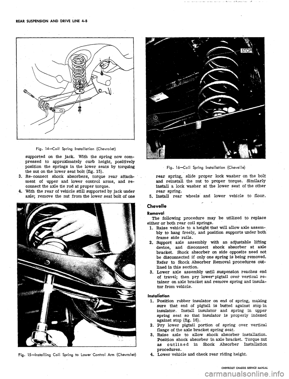
14—Coil Spring Installation (Chevrolet)
supported on the jack. With the spring now com-
pressed to approximately curb height, positively
position the springs in the lower seats by torquing
the nut on the lower seat bolt (fig. 15).
Re-connect shock absorbers, torque rear attach-
ment of upper and lower control arms, and re-
connect the axle tie rod at proper torque.
With the rear of vehicle still supported by jack under
axle;
remove the nut from the lower seat bolt of one
Fig.
15—Installing Coil Spring to Lower Control Arm (Chevrolet)
Fig.
16—Coil Spring Installation (Chevelle)
rear spring, slide proper lock washer on the bolt
and reinstall the nut to proper torque. Similarly
install a lock washer at the lower seat of the other
rear spring.
5.
Install rear wheels and lower vehicle to floor.
Chevelle
Removal
The following procedure may be utilized to replace
either or both rear coil springs.
1.
Raise vehicle to a height that will allow axle assem-
bly to hang freely, and position supports under both
frame side rails.
2.
Support axle assembly with an adjustable lifting
device, and disconnect shock absorber at axle
bracket. Shock absorber on side opposite need not
be disconnected if only one spring is being removed.
Refer to Shock Absorber Removal procedures out-
lined in this section.
3.
Lower axle assembly until suspension reaches end
of travel; then pry lower% pigtail over vertical re-
tainer on axle bracket and remove spring and insula-
tor from vehicle.
Installation
1.
Position rubber insulator on end of spring, making
sure that end of pigtail is butted against stop in
insulator. Install insulator and spring in upper
spring seat so that insulator is properly indexed
against stop (fig. 16).
2.
Pry lower pigtail portion of spring over vertical
flange of the axle bracket spring seat.
3.
Raise axle to allow shock absorber installation.
Position shock absorber in axle bracket. Torque nut
as outlined in Shock Absorber Installation
procedures.
4.
Lower vehicle and check rear riding height.
CHEVROLET CHASSIS SERVICE MANUAL
Page 200 of 659
REAR SUSPENSION AND DRIVE LINE 4-10
Fig.
22—Rear Spring Shackle Exploded View—Station Wagon
(Chevy II)
4.
Place upper spring pad cushion on spring. Raise
spring, making sure spring cushion ribs index with
locating ribs in axle housing spring seat, and insert
spring front eye and bushing in frame bracket. In-
stall spring eye bolt, bushing, retainer, lock washer
and nut. Do not torque at this point.
5.
Place lower spring pad cushion on spring, indexing
it over locating dowel.
NOTE: Upper pad correctly installed when
aligned with lower pad.
6. Place lower mounting plate into position over lo-
cating dowel on spring pad, install four locknuts and
insert shock absorber lower eye bolt.
7.
Remove adjustable jackstands, lower vehicle to floor
and bounce several times. Torque all affected parts
to specifications. Incorrect bushing preload may
result if spring eye bolts are torqued prior to
lowering vehicle.
Camaro (Fig. 23)
Removal
1.
Raise rear of vehicle sufficiently to allow axle as-
sembly to hang freely; then support weight of vehicle
at both frame side rails and near front eye of
spring.
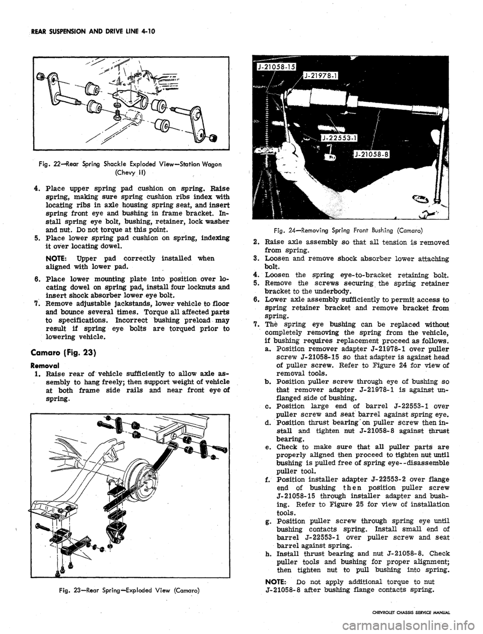
Fig.
23—Rear Spring—Exploded View (Camaro)
Fig.
24—Removing Spring Front Bushing (Camaro)
2.
Raise axle assembly so that all tension is removed
from spring.
3.
Loosen and remove shock absorber lower attaching
bolt.
4.
Loosen the spring eye-to-bracket retaining bolt.
5.
Remove the screws securing the spring retainer
bracket to the underbody.
6. Lower axle assembly sufficiently to permit access to
spring retainer bracket and remove bracket from
spring.
7.
The spring eye bushing can be replaced without
completely removing the spring from the vehicle,
if bushing requires replacement proceed as follows.
a. Position remover adapter J-21978-1 over puller
screw J-21058-15 so that adapter is against head
of puller screw. Refer to Figure 24 for view of
removal tools.
b.
Position puller screw through eye of bushing so
that remover adapter J-21978-1 is against un-
flanged side of bushing.
C. Position large end of barrel J-22553-1 over
puller screw and seat barrel against spring eye.
d. Position thrust bearing on puller screw then in-
stall and tighten nut J-21058-8 against thrust
bearing.
e. Check to make sure that all puller parts are
properly aligned then proceed to tighten nut until
bushing is pulled free of spring eye--disassemble
puller tool.
f. Position installer adapter J-22553-2 over flange
end of bushing then position puller screw
J-21058-15 through installer adapter and bush-
ing. Refer to Figure 25 for view of installation
tools.
g. Position puller screw through spring eye until
bushing contacts spring. Install small end of
barrel J-22553-1 over puller screw and seat
barrel against spring.
h. Install thrust bearing and nut J-21058-8. Check
puller tools and bushing for proper alignment;
then tighten nut to pull bushing into spring.
NOTE: Do not apply additional torque to nut
J-21058-8 after bushing flange contacts spring.
CHEVROLET CHASSIS SERVICE MANUAL
Page 202 of 659
REAR SUSPENSION AND DRIVE LINE 4-12
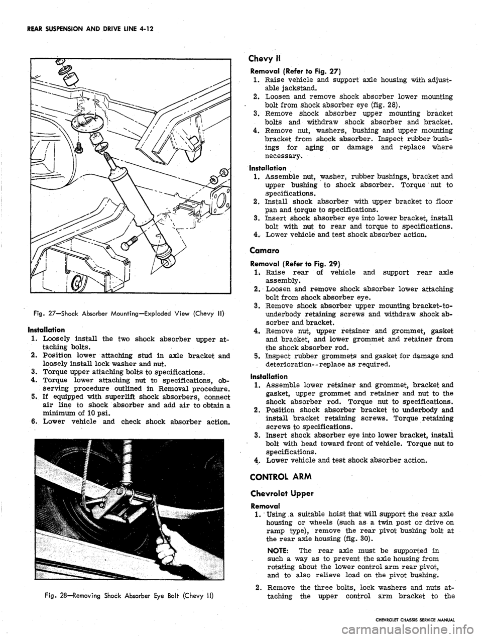
Fig.
27—Shock Absorber Mounting—Exploded View (Chevy II)
Installation
1.
Loosely install the two shock absorber upper at-
taching bolts.
2.
Position lower attaching stud in axle bracket and
loosely install lock washer and nut.
3.
Torque upper attaching bolts to specifications.
4.
Torque lower attaching nut to specifications, ob-
serving procedure outlined in Removal procedure.
5.
If equipped with superlift shock absorbers, connect
air line to shock absorber and add air to obtain a
minimum of 10 psi.
6. Lower vehicle and check shock absorber action.
Fig.
28—Removing Shock Absorber Eye Bolt (Chevy II)
Chevy H
Removal (Refer to Fig. 27)
1.
Raise vehicle and support axle housing with adjust-
able jackstand.
2.
Loosen and remove shock absorber lower mounting
bolt from shock absorber eye (fig. 28).
3.
Remove shock absorber upper mounting bracket
bolts and withdraw shock absorber and bracket.
4.
Remove nut, washers, bushing and upper mounting
bracket from shock absorber. Inspect rubber bush-
ings for aging or damage and replace where
necessary.
Installation
1.
Assemble nut, washer, rubber bushings, bracket and
upper bushing to shock absorber. Torque nut to
specifications.
2.
Install shock absorber with upper bracket to floor
pan and torque to specifications.
3.
Insert shock absorber eye into lower bracket, install
bolt with nut to rear and torque to specifications.
4.
Lower vehicle and test shock absorber action.
Comoro
Removal (Refer to Fig. 29)
1.
Raise rear of vehicle and support rear axle
assembly.
2.
Loosen and remove shock absorber lower attaching
bolt from shock absorber eye.
3.
Remove shock absorber upper mounting bracket-to-
iiinderbody retaining screws and withdraw shock ab-
sorber and bracket.
4.
Remove nut, upper retainer and grommet, gasket
and bracket, and lower grommet and retainer from
the shock absorber rod.
5.
Inspect rubber grommets and gasket for damage and
deterioration--replace as required.
Installation
1.
Assemble lower retainer and grommet, bracket and
gasket, upper grommet and retainer and nut to the
shock absorber rod. Torque nut to specifications.
2.
Position shock absorber bracket to underbody and
install bracket retaining screws. Torque retaining
screws to specifications.
3.
Insert shock absorber eye into lower bracket, install
bolt with head toward front of vehicle. Torque nut to
specifications.
4.
Lower vehicle and test shock absorber action.
CONTROL ARM
Chevrolet Upper
Removal
1.
*
Using,a suitable hoist that will support the rear axle
housing or wheels (such as a twin post or drive on
ramp type), remove the rear pivot bushing bolt at
the rear axle housing (fig. 30).
NOTE: The rear axle must be supported in
such a way as to prevent the axle housing from
rotating about the lower control arm rear pivot,
and to also relieve load on the pivot bushing.
2.
Remove the three bolts, lock washers and nuts at-
taching the upper control arm bracket to the
CHEVROLET CHASSIS SERVICE MANUAL
Page 204 of 659
REAR SUSPENSION AND DRIVE LINE 4-14
Fig.
32—Upper Control Arm Bushing Installation (Chevrolet)
Installation
1.
Position rear of control arm into axle bracket and
loosely install the pivot bolt.
2.
Align the forward end of the control arm with the
rear crossmember and install front bracket bolts
through holes. Raise or lower nose of carrier as
/ required to help align bracket and crossmember.
3.
Install crossmember reinforcement plate, lock
washers and nuts to retain bracket in place.
4.
Position vehicle so that weight is on suspension
components and torque all affected parts to
specifications.
Chevrolet Lower
Removal
1.
Raise vehicle and remove shock absorber and spring
as outlined in this section.
NOTE:
If both rear suspension lower control
arms are to be removed, support the rear axle
in such a manner to prevent damage to brake
lines and to prevent assembly from falling.
2.
Note position of control arm in forward attaching
bracket and disconnect control arm at forward and
rearward attaching points. Remove assembly from
vehicle.
Bushing Replacement
Lower control arm front and rear bushing assemblies
are not interchangeable and require separate removal
and installation procedures.
1.
Replace the front bushing as follows.
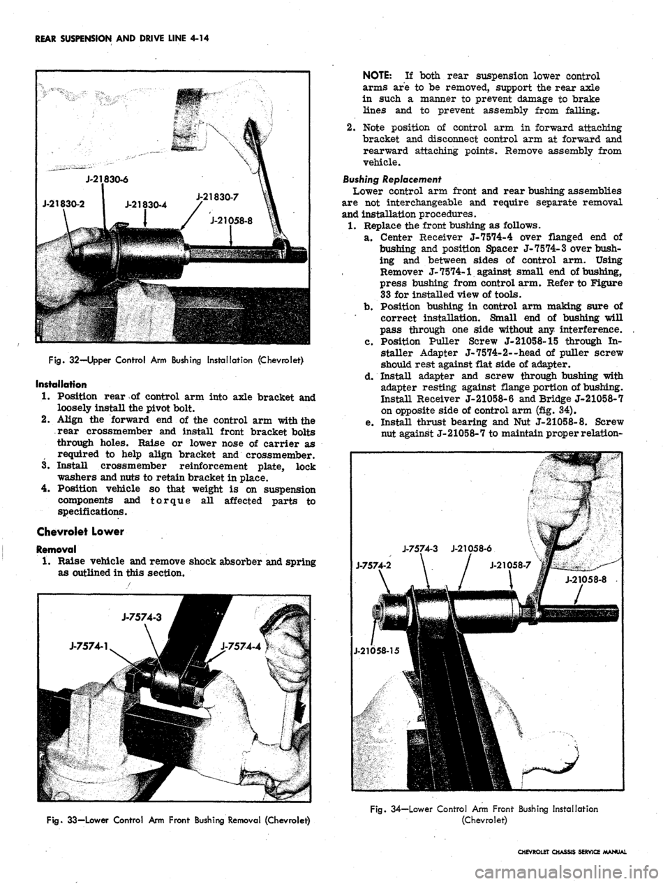
a. Center Receiver J-7574-4 over flanged end of
bushing and position Spacer J-7574-3 over bush-
ing and between sides of control arm. Using
Remover J- 7574-1 against small end of bushing,
press bushing from control arm. Refer to Figure
33 for installed view of tools.
b.
Position bushing in control arm making sure of
correct installation. Small end of bushing will
pass through one side without any interference.
c. Position Puller Screw J-21058-15 through In-
staller Adapter J-7574-2--head of puller screw
should rest against flat side of adapter.
d. Install adapter and screw through bushing with
adapter resting against flange portion of bushing.
Install Receiver J-21058-6 and Bridge J^-21058-7
on opposite side of control arm (fig. 34).
e. Install thrust bearing and Nut J-21058-8. Screw
nut against J-21058-7 to maintain proper relation-
Fig.
33—Lower Control Arm Front Bushing Removal (Chevrolet)
Fig. 34—Lower Control Arm Front Bushing Installation
(Chevrolet)
CHEVROLET CHASSIS SERVICE MANUAL