fuse CHEVROLET CAMARO 1967 1.G Chassis User Guide
[x] Cancel search | Manufacturer: CHEVROLET, Model Year: 1967, Model line: CAMARO, Model: CHEVROLET CAMARO 1967 1.GPages: 659, PDF Size: 114.24 MB
Page 104 of 659
HEATER AND AIR CONDITIONING 1A-81
HORN RELAY
r
CONN.-
14 BROWN
(TO FUSE
PANEL)
BATTERY
1
—I ^ COMPR
ESSOR
DASH y
V-^ PANEL \
GROMMET—%
1 \
_ J~ ") "^
>14 BLACK/RED STRIPE-
FUSE .20 AMP.
•WIRE ASM. BLOWER-
MOTOR
14 BLACK 1
IGNITION SWITCH1
(ACCESSORY
TERMINAL)
CONTROL SWITCH
-RESISTOR
CONN.
•14 TAN
•16 BLACK
LIGHT BLUE STRIPE
•THERMOSTAT CONTROL
EVAPORATOR & BLOWER ASM.
Fig.
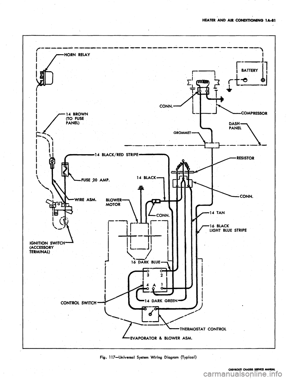
117—Universal System Wiring Diagram (Typical)
CHEVROLET CHASSI
Page 105 of 659
HEATER AND AIR CONDITIONING 1A-82
•BATTERY
(POS)
CABLE
NOTE
When
control
switch*
is !TOFF"
&
Air
Cond
is
"ON"
(Control
knob
pulled
but) the
blower
fan'will
run at low
speed.
CONTROL
SWITCH
CONNECTIONS
OFF
LOW
MED
HIGH
B
TO
NONE
B
TO L
BTOL&M
B
TO L
&
H
COMPRESSOR
GROUND
WIRE
ASM
BATTERY
(NEGATIVE)
CABLE
COMPRESSOR
ASM
DASHPAJSTEL
GROMMET
16DG
CONTROL
SWITCH
RESISTOR
ASM
14LBL
14BRN
CLUTCH
COIL
EXTENSION
WIRE
ASM
-14BRN--N
JUNC
BLOCKi
OSTATIC
SWITCH
CONTACTS
NORMALLY
CLOSED
STARTING
MOTOR
SOLENOID
BLOWER
MOTOR
AIR
COND
CONTROL
(PUSH-PULL)
KNOB
DOOR
SWITCH
(PUSH
BUTTON
NORMALLY
CLOSED)
RELAY
ASM
HORN
RELAY
DIVERTER
DOOR CABLE
FUSE
PANEL
EVAPORATOR
ASM
IGNITION SWITCH-
ACCESSORY TERMINAL)
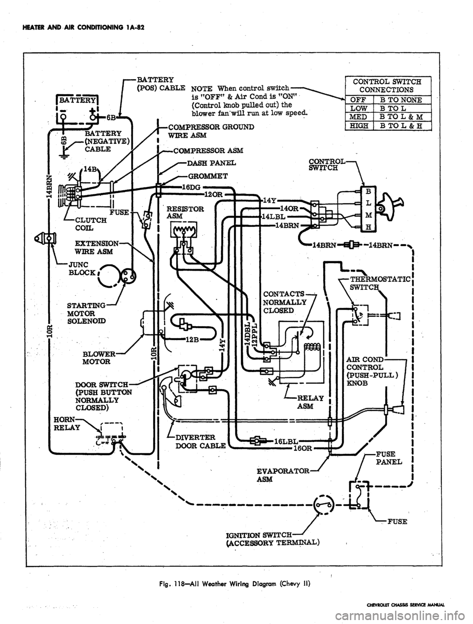
Fig. 118—All Weather Wiring Diagram (Chevy II)
CHEVROLET CHASSIS SERVICE MANUAL
Page 219 of 659
REAR SUSPENSION AND DRIVE LINE 4-29
REAR AXLE NOISE DIAGNOSIS
Mechanical failures of the rear axle are relatively
simple to locate and correct. Noise in a rear axle is a
little more difficult to diagnose and repair. One of the
most essential parts of rear axle service is proper
diagnosis.
Ail rear axles are noisy to a certain degree. The
action of transmitting the high engine torque through a
90° turn reducing propeller shaft speed produces noise
in rear axles. This point establishes the need for a line
between normal and abnormal or unacceptable axle
noises.
Slight axle noise heard only at a certain speed or under
remote conditions must be considered normal. Axle noise
tends to "peak" at varying speeds and the noise is in no
way indicative of trouble in the axle.
If noise is present in an objectionable form, loud or at
all speeds, an effort should be made to isolate the noise
as being in one particular unit of the vehicle. Axle noise
is often confused with other noises such as tire noise,
transmission noise, propeller shaft vibration and uni-
versal joint noise. Isolation of the noise as in any one
unit requires skill and experience. An attempt to elimini-
ate a slight noise may baffle even the best of diagnos-
ticians. Such practices as raising tire pressure to
eliminate tire noise, listening for the noise at varying
speeds and on drive, float and coast, and under proper
highway conditions, turning the steering wheel from left
to right to detect wheel bearing noise, will aid even the
beginner in detecting alleged axle noises. Axle noises
fall into two categories: gear noise and bearing noise.
GEAR NOISE
Abnormal gear noise can be recognized since it pro-
duces a cycling pitch and will be very pronounced in the
speed range at which it occurs, appearing under either
"drive," "float" or "coast" conditions. Gear noise
tends to peak in a narrow speed range or ranges, while
bearing noise will tend to remain constant in pitch. Ab-
normal gear noise is rare and usually originates from
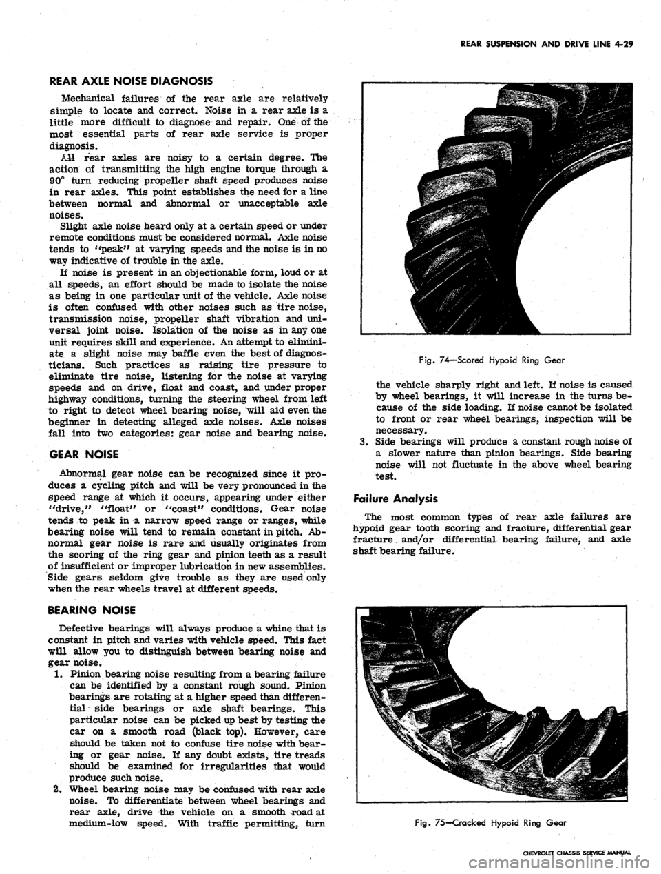
the scoring of the ring gear and pinion teeth as a result
of insufficient or improper lubrication in new assemblies.
Side gears seldom give trouble as they are used only
when the rear wheels travel at different speeds.
BEARING NOISE
Defective bearings will always produce a whine that is
constant in pitch and varies with vehicle speed. This fact
will allow you to distinguish between bearing noise and
gear noise.
1.
Pinion bearing noise resulting from a bearing failure
can be identified by a constant rough sound. Pinion
bearings are rotating at a higher speed than differen-
tial side bearings or axle shaft bearings. This
particular noise can be picked up best by testing the
car on a smooth road (black top). However, care
should be taken not to confuse tire noise with bear-
ing or gear noise. If any doubt exists, tire treads
should be examined for irregularities that would
produce such noise.
2.
Wheel bearing noise may be confused with rear axle
noise. To differentiate between wheel bearings and
rear axle, drive the vehicle on a smooth road at
medium-low speed. With traffic permitting, turn
Fig.
74—Scored Hypoid Ring Gear
the vehicle sharply right and left. If noise is caused
by wheel bearings, it will increase in the turns be-
cause of the side loading. If noise cannot be isolated
to front or rear wheel bearings, inspection will be
necessary.
3.
Side bearings will produce a constant rough noise of
a slower nature than pinion bearings. Side bearing
noise will not fluctuate in the above wheel bearing
test.
Failure Analysis
The most common types of rear axle failures are
hypoid gear tooth scoring and fracture, differential gear
fracture. and/or differential bearing failure, and axle
shaft bearing failure.
Fig.
75-Cracked Hypoid Ring Gear
CHEVROLET CHASSIS SERVICE MANUAL
Page 254 of 659
BRAKES 5-21
brake fluid. Coat the primary and secondary seals
on the secondary piston with clean brake fluid. Insert
the secondary piston spring retainer into the sec-
ondary piston spring. Place the retainer and spring
down over the end of the secondary piston until the
retainer locates inside of the lips of the primary
cup.
10.
Hold the master cylinder with the open end of the
bore down. Push the secondary piston into the bore
until the spring seats against the closed end of the
bore.
11.
Position the master cylinder in a vise with the
open end of the bore up. Coat the primary and
secondary seal on the primary piston with clean
brake fluid. Push the primary piston assembly,
spring end first, into the bore of the master cylinder*
Hold the piston down and snap the lock ring into
position in the small groove in the I.D. of the bore.
12.
Push the primary piston down to move the secondary
piston forward far enough to clear the stop screw
hole in the bottom of the front fluid reservoir. Install
the stop screw.
13.
Install reservoir diaphragm in the reservoir cover
and install the cover on the main cylinder. Push
bail wire into position to secure the reservoir cover.
Installation
1.
Assemble the push rod through the push rod retainer,
if it has been disassembled.
2.
Push the retainer over the end of the main cylinder.
Assemble new boot over push rod and press it down
over the push rod retainer. Slide new mounting
gasket into position.
3.
Secure .the main cylinder to the firewall with mount-
ing bolts.
4.
Connect the push rod clevis to the brake pedal with
pin and retainer.
5. Connect the brake lines to the main cylinder.
6. Fill the main cylinder reservoirs to the levels
shown in Figure 8. Bleed the brake system as out-
lined in this section.
7. K necessary, adjust the brake pedal free play as
outlined in this section.
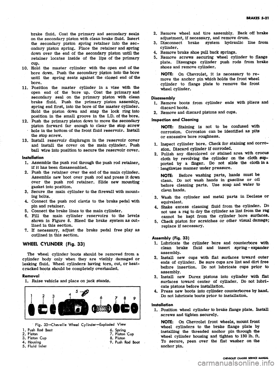
WHEEL CYLINDER (Fig. 33)
The wheel cylinder boots should be removed from a
cylinder body only when they are visibly damaged or
leaking fluid. Wheel cylinders having torn, cut, or heat-
cracked boots should be completely overhauled.
Removal
1.
Raise vehicle and place on jack stands.
Fig.
33-Chevelle Wheel Cylinder—Exploded View
1.
Push Rod Boot 6. Spring
2.
Piston 7. Piston Cup
3. Piston Cup 8. Piston
4.
Housing 9. Push Rod Boot
5. Fluid Inlet
2.
Remove wheel and tire assembly. Back off brake
adjustment, if necessary, and remove drum.
3.
Disconnect brake system hydraulic line from
cylinder.
4.
Remove brake shoe pull back springs.
5. Remove screws securing wheel cylinder to flange
plate. Disengage cylinder push rods from brake
shoes and remove cylinder.
NOTE:
On Chevrolet, it is necessary to re-
move the anchor pin which holds the front wheel
cylinder to flange plate to remove the front
wheel cylinder.
Disassembly
1.
Remove boots from cylinder ends with pliers and
discard boots.
2.
Remove and discard pistons and cups.
Inspection and Cleaning
NOTE:
Staining is not to be confused with
corrosion. Corrosion can be identified as pits
or excessive bore roughness.
1.
Inspect cylinder bore. Check for staining and corro-
sion.
Discard cylinder if corroded.
2.
Polish any discolored or stained area with crocus
cloth by revolving the cylinder on the cloth sup-
ported by a finger. Do not slide tfce cloth in a
lengthwise manner under pressure.
NOTE:
Before washing parts, hands must be
clean. Do not wash hands in gasoline or oil
before cleaning parts. Use soap and water to
clean hands.
3.
Wash the cylinder and metal parts in Declene or
equivalent.
4.
Shake excess cleaning fluid from the cylinder-. Do
not use a rag to dry the cylinder as lint from the rag
cannot be kept from the cylinder bore surfaces.
5. Check piston for scratches or other visual damage;
replace if necessary.
Assembly (Fig. 33)
1.
Lubricate the cylinder bore and counterbore with
clean brake fluid and insert spring - expander
assembly.
2.
Install new cups with flat surfaces toward outer
ends of cylinder. Be sure cups are lint and dirt free
before insertion. Do not lubricate cups prior to
assembly.
3.
Install new Durex pistons into cylinder with flat
surfaces toward center of cylinder. Do not lubri-
cate pistons before installation.
4.
Press new boots into cylinder counterbores by hand.
Do not lubricate boots prior to installation.
Installation
1.
Position wheel cylinder to brake flange plate. Install
screws and tighten securely.
NOTE:
On Chevrolet front wheels, mount front
wheel cylinders to the brake flange plate by
installing the threaded anchor pin through the
wheel cylinder housing and tighten to 130 lb. ft.
To secure, peen over the flat washer on the
anchor pin.
CHEVROLET CHASSIS SERVICE MANUAL
Page 334 of 659
ENGINE-ELECTRICAL 6Y-9
63 AMP 1
MODELS ONLY'
BATTERY FUSIBLE
LINK
HORN
FUSIBLE LINK'
TRANSISTOR
FUSIBLE LINK'
Fig.
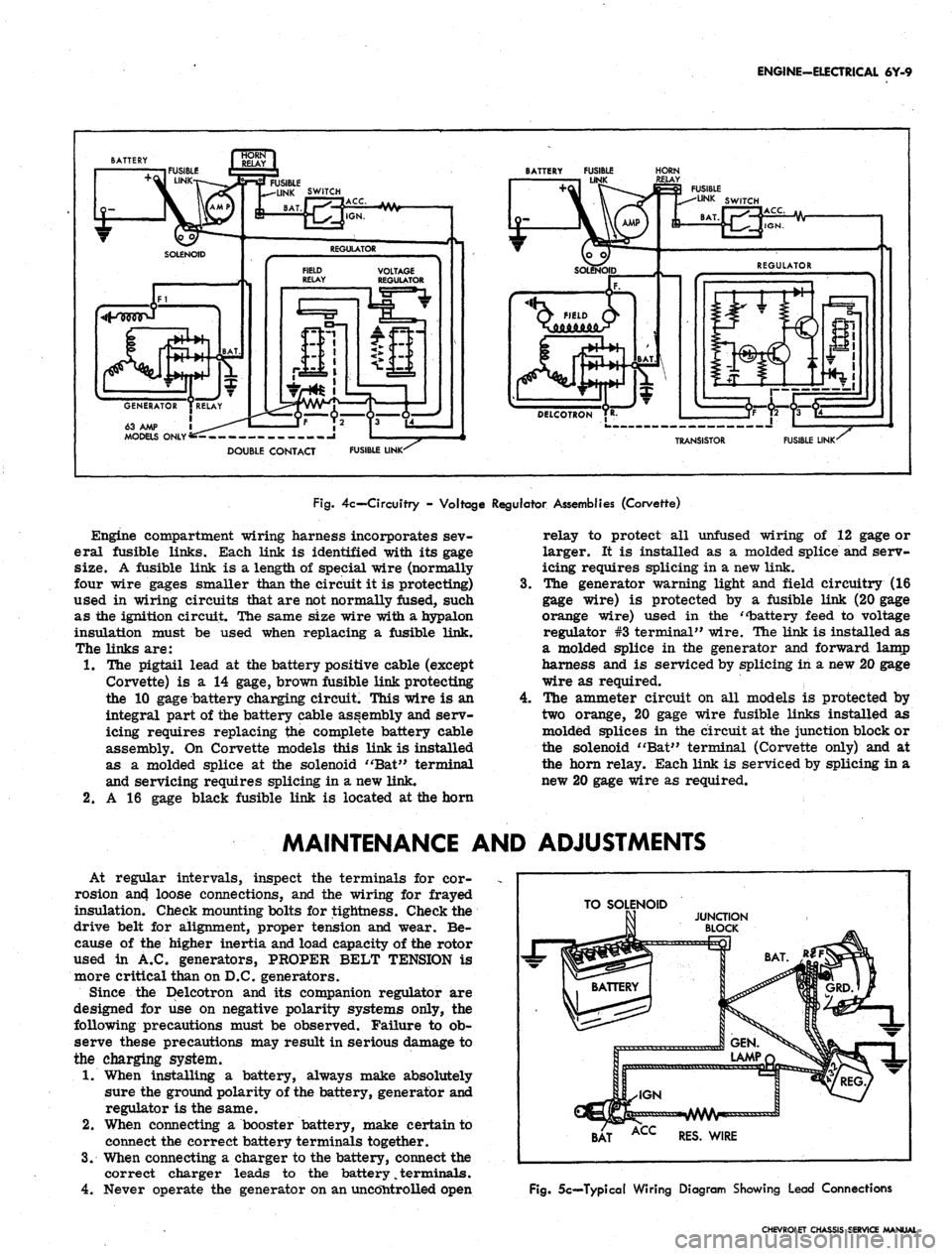
4c— Circuitry - Voltage Regulator Assemblies (Corvette)
Engine compartment wiring harness incorporates sev-
eral fusible links. Each link is identified with its gage
size. A fusible link is a length of special wire (normally
four wire gages smaller than the circuit it is protecting)
used in wiring circuits that are not normally fused, such
as the ignition circuit. The same size wire with a hypalon
insulation must be used when replacing a fusible link.
The links are:
1.
The pigtail lead at the battery positive cable (except
Corvette) is a 14 gage, brown fusible link protecting
the 10 gage battery charging circuit. This wire is an
integral part of the battery cable assembly and serv-
icing requires replacing the complete battery cable
assembly. On Corvette models this link is installed
as a molded splice at the solenoid "Bat" terminal
and servicing requires splicing in a new link.
2.
A 16 gage black fusible link is located at the horn
4.
relay to protect all unfused wiring of 12 gage or
larger. It is installed as a molded splice and serv-
icing requires splicing in a new link.
The generator warning light and field circuitry (16
gage wire) is protected by a fusible link (20 gage
orange wire) used in the "battery feed to voltage
regulator #3 terminal" wire. The link is installed as
a molded splice in the generator and forward lamp
harness and is serviced by splicing in a new 20 gage
wire as required.
The ammeter circuit on all models is protected by
two orange, 20 gage wire fusible links installed as
molded splices in the circuit at the junction block or
the solenoid "Bat" terminal (Corvette only) and at
the horn relay. Each link is serviced by splicing in a
new 20 gage wire as required.
MAINTENANCE AND ADJUSTMENTS
At regular intervals, inspect the terminals for cor-
rosion an4 loose connections, and the wiring for frayed
insulation. Check mounting bolts for tightness. Check the
drive belt for alignment, proper tension and wear. Be-
cause of the higher inertia and load capacity of the rotor
used in A.C. generators, PROPER BELT TENSION is
more critical than on D.C. generators.
Since the Delcotron and its companion regulator are
designed for use on negative polarity systems only, the
following precautions must be observed. Failure to ob-
serve these precautions may result in serious damage to
the charging system.
1.
When installing a battery, always make absolutely
sure the ground polarity of the battery, generator and
regulator is the same.
2.
When connecting a booster battery, make certain to
connect the correct battery terminals together.
3.
When connecting a charger to the battery, connect the
correct charger leads to the battery
%
terminals.
4.
Never operate the generator on an uncontrolled open
TO SOLENOID
BAT ACC RES. WIRE
Fig.
5c—Typical Wiring Diagram Showing Lead Connections
CHEVROLET CHASSIS SERVICE MANUAL
Page 372 of 659
CLUTCH AND TRANSMISSIONS 7-13
PULL-IN
WINDING
li
HOLD-IN
WINDING
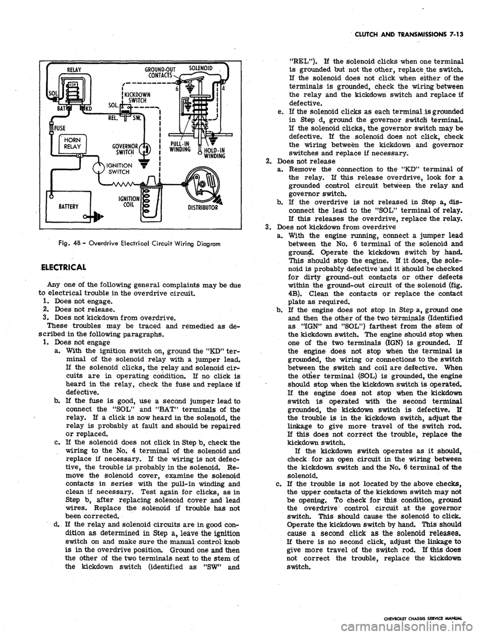
Fig.
4B -
Overdrive Electrical Circuit Wiring Diagram
ELECTRICAL
Any one of the following general complaints may be due
to electrical trouble in the overdrive circuit.
1.
Does not engage.
2.
Does not release.
3.
Does not kickdown from overdrive.
These troubles may be traced and remedied as de-
scribed in the following paragraphs.
1.
Does not engage
a. With the ignition switch on, ground the "KD" ter-
minal of the solenoid relay with a jumper lead.
If the solenoid clicks, the relay and solenoid cir-
cuits are in operating condition. If no click is
heard in the relay, check the fuse and replace if
defective.
b.
If the fuse is good, use a second jumper lead to
connect the "SOL" and "BAT" terminals of the
relay. If a click is now heard in the solenoid, the
relay is probably at fault and should be repaired
or replaced.
c. If the solenoid does not click in Step b, check the
wiring to the No. 4 terminal of the solenoid and
replace if necessary. If the wiring is not defec-
tive,
the trouble is probably in the solenoid. Re-
move the solenoid cover, examine the solenoid
contacts in series with the pull-in winding and
clean if necessary. Test again for clicks, as in
Step b, after replacing solenoid cover and lead
wires.
Replace the solenoid if trouble has not
been corrected.
d. If the relay and solenoid circuits are in good con-
dition as determined in Step a, leave the ignition
switch on and make sure the manual control knob
is in the overdrive position. Ground one and then
the other of the two terminals next to the stem of
the kickdown switch (identified as "SW" and
?fREL"). K the solenoid clicks when one terminal
is grounded but not the other, replace the switch.
If the solenoid does not click when either of the
terminals is grounded, check the wiring between
the relay and the kickdown switch and replace if
defective.
e. If the solenoid clicks as each terminal is grounded
in Step d, ground the governor switch terminal.
If the solenoid clicks, the governor switch may be
defective. If the solenoid does not click, check
the wiring between the kickdown and governor
switches and replace if necessary.
2.
Does not release
a. Remove the connection to the "KD" terminal of
the relay. If this release overdrive, look for a
grounded control circuit between the relay and
governor switch.
b.
If the overdrive is not released in Step a, dis-
connect the lead to the "SOL" terminal of relay.
If this releases the overdrive, replace the relay.
3.
Does not kickdown from overdrive
a. With the engine running, connect a jumper lead
between the No. 6 terminal of the solenoid and
ground. Operate the kickdown switch by hand.
This should stop the engine. If it does, the sole-
noid is probably defective and it should be checked
for dirty ground-out contacts or other defects
within the ground-out circuit of the solenoid (fig.
4B).
Clean the contacts or replace the contact
plate as required.
b.
If the engine does not stop in Step a, ground one
and then the other of the two terminals (Identified
as "IGN" and "SOL") farthest from the sfem of
the kickdown switch. The engine should stop when
one of the two terminals (IGN) is grounded. If
the engine does not stop when the terminal is
grounded, the wiring or connections to the switch
between the switch and coil are defective. When
the btlier terminal (SOL) is grounded, the engine
should stop when the kickdown switch is operated.
If the engine does not stop when the kickdown
switch is operated with the second terminal
grounded, the kickdown switch is defective. If
the trouble is in the kickdown switch, adjust the
linkage to give more travel of the switch rod.
If this does not correct the trouble, replace the
kickdown switch.
If the kickdown switch operates as it should,
check for an open circuit in the wiring between
the kickdown switch and the No. 6 terminal of the
solenoid.
c. If the trouble is not located by the above checks,
the upper contacts of the kickdown switch may not
be opening. To check for this condition, ground
the overdrive control circuit at the governor
switch. This should cause the solenoid to click.
Operate the kickdown switch by hand. This should
cause a second click as the solenoid releases.
If there is no second click, adjust the linkage to
give more travel of the switch rod. If this does
not correct the trouble, replace the kickdown
switch.
CHEVROLET CHASSIS SERVICE MANUAL
Page 484 of 659
WHEELS AND TIRES 10-4
the road and it slips, grinding off the tread on the inside
half of the tire at an excessive rate. This type of tire
shows much the same appearance of tread wear as tire
wear caused by negative camber.
Second, the transfer of weight may also over-load the
outside tires so much that they are laterally distorted
resulting in excessive wear on the outside half of the
tire producing a type of wear like that caused by ex-
cessive positive camber.
Cornering wear can be most easily distinguished from
abnormal camber wear by the rounding of the outside
shoulder or edge of the tire and by the roughening of the
tread surface which denotes abrasion.
Cornering wear often produces a fin or raised portion
along the inside edge of each row in the tread pattern.
In some cases this fin is almost as pronounced as a
toe-in fin, and in others, it tapers into a row of tread
blocks to such an extent that the tire has a definite step
wear appearance.
The only remedy for cornering wear is proper in-
struction of owners.
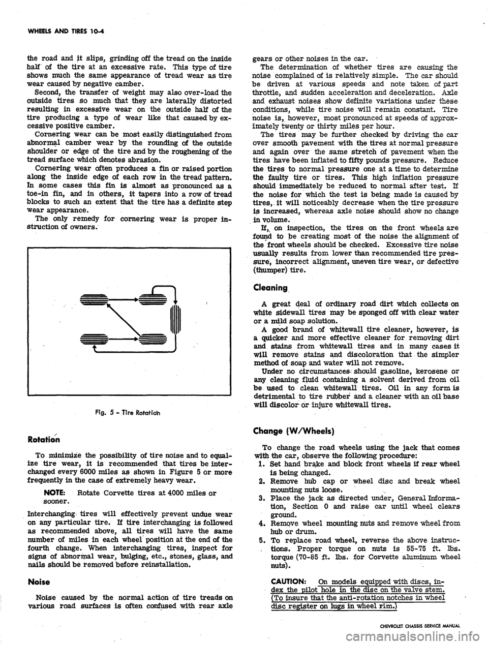
Fig.
5 - Tire Rotatidh
Rotation
To minimize the possibility of tire noise and to equal-
ize tire wear, it is recommended that tires be inter-
changed every 6000 miles as shown in Figure 5 or more
frequently in the case of extremely heavy wear.
NOTE:
Rotate Corvette tires at 4000 miles or
sooner.
Interchanging tires will effectively prevent undue wear
on any particular tire. II tire interchanging is followed
as recommended above, all tires will have the same
number of miles in each wheel position at the end of the
fourth change. When interchanging tires, inspect for
signs of abnormal wear, bulging, etc., stones, glass, and
nails should be removed before reinstallation.
Noise
Noise caused by the normal action of tire treads on
various road surfaces is often confused with rear axle
gears or other noises in the car.
The determination of whether tires are causing the
noise complained of is relatively simple. The car should
be driven at various speeds and note taken of part
throttle, and sudden acceleration and deceleration. Axle
and exhaust noises show definite variations under these
conditions, while tire noise will remain constant. Tire
noise is, however, most pronounced at speeds of approx-
imately twenty or thirty miles per hour.
The tires may be further checked by driving the ear
over smooth pavement with the tires at normal pressure
and again over the same stretch of pavement when the
tires have been inflated to fifty pounds pressure. Reduce
the tires to normal pressure one at a time to determine
the faulty tire or tires. This high inflation pressure
should immediately be reduced to normal after test. If
the noise for which the test is being made is caused by
tires,.
it will noticeably decrease when the tire pressure
is increased, whereas axle noise should show no change
in volume.
If, on inspection, the tires on the front wheels are
found to be creating most of the noise the alignment of
the front wheels should be checked. Excessive tire noise
usually results from lower than recommended tire pres-
sure, incorrect alignment, uneven tire wear, or defective
(thumper) tire.
Cleaning
A great deal of ordinary road dirt which collects on
white sidewall tires may be sponged off with clear water
or a mild soap solution.
A good brand of whitewall tire cleaner, however, is
a quicker and more effective cleaner for removing dirt
and stains from whitewall tires and in many cases it
will remove stains and discoloration that the simpler
method of soap and water will not remove.
Under no circumstances should gasoline, kerosene or
any cleaning fluid containing a solvent derived from oil
be used to clean whitewall tires. Oil in any form is
detrimental to tire rubber and a cleaner with an oil base
will discolor or injure whitewall tires.
Change (W/Wheels)
To change the road wheels using the jack that comes
with the car, observe the following procedure:
1.
Set hand brake and block front wheels if rear wheel
is being changed.
2.
Remove hub cap or wheel disc and break wheel
mounting nuts loose.
3.
Place the jack as directed tinder, General Informa-
tion,
Section 0 and raise car until wheel clears
ground.
4.
Remove wheel mounting nuts and remove wheel from
hub or drum.
5. To replace road wheel, reverse the above instrue-
. tions. Proper torque on nuts is 55-75 ft. lbs.
torque (70-85 ft. lbs. for Corvette aluminum wheel
nuts).
CAUTION: On models equipped with discs, in-
dex the pilot hole in the disc on the valve stem.
(To insure that the anti-rotation notches in wheel
disc register on lugs in wheel rim.)
CHEVROLET CHASSIS SERVICE MANUAL
Page 486 of 659
WHEELS AND TIRES
10-6
lifted on the rim to force the top tire bead
against the top rim flange. The weight of the
tire will seat the bottom bead.
Repair
When a tire loses all or most of its air pressure,
particularly when driving at high legal speeds on today1 s
super-highways, recommended procedure is to remove it
from the wheel for complete inspection to be sure no
tire damage has occurred. Punctured tires should be
removed from the wheel and permanently repaired from
the inside.
Externally applied plug type repairs should be con-?
sidered temporary and the tire should be permanently
repaired as soon as possible.
Hot Patch Method
It is essential to thoroughly clean and remove all
foreign matter from the hole left by the puncturing-object
without enlarging the injury and then follow the manu-
facturer's instructions for vulcanizing the patch.
Rubber Plug Methods
There are several types of rubber plugs--some are
inserted from the inside of the tire; others are inserted
from the outside of the tire without demounting the tire
from the rim.
When using the plug method be sure to clean and
lubricate the hole with repair cement before inserting
the plug. Your tire supplier has available complete kits
containing materials, tools and detailed instructions for
making repairs with plugs. Follow instructions in the kit
you use.
Cold Patch Method
(Self Vulcanizing Type)
In this method it is essential to thoroughly clean and
remove all foreign matter from the hole left by the
puncturing object without enlarging the injury; also on
the inside of the tire, buff an area large enough for the
patch. Follow the manufacturer1 s instructions for appli-
cation of the special cement and self-vulcanizing cold
patch.
Pressure Gun Method
Several types of pressure guns are available. Consult
your tire supplier for materials and instructions.
Tire Installation Safety Precautions
When tires are mounted on dirty or corroded rims, or
when they are not properly centered on rims, the tire
bead may "bind" on the rim, and refuse to seat. Allowing
pressure to continue to build up within the assembly in
an attempt to seat the tire bead is a DANGEROUS PRAC-
TICE which can result in a broken tire bead, and serious
injury to the serviceman.
1.
Make sure that rim flanges and bead ledge (espe-
cially hump and radius) areas are smooth and clean.
Remove any oxidized rubber, dried soap solution,
rust, heavy paint, etc. with a wire brush, or, in ex-
treme cases, a file.
2.
Lubricate tire beads, rim flanges, and bead ledge
areas with a liberal amount of thin vegetable oil
soap solution, or approved rubber lubricant,
3.
Insure that air pressure build-up during the bead
seating process is not allowed to exceed 40 pounds
pressure. If beads have not seated by the time pres-
sure reaches 40 pounds, assembly should be deflated,
re-positioned on rim, re-lubricated and re-inflated.
4.
Make sure valve core is inserted in valve stem
prior to inflating.
5.
Use an extension gauge with clip on chuck so air
pressure build-up can be closely watched and so
that you can stand well back from the assembly
during the bead seating process.
WHEELS
Valve Assembly
Replace
NOTE: Always use new valve assembly when
replacing.
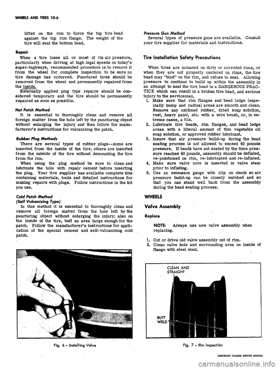
1.
Cut or drive old valve assembly out of rim.
2.
Clean valve hole and surrounding area on inside of
flange with steel wool.
Fig. 6 - Installing Valve
Fig. 7 - Rim Inspection
CHEVROLET CHASSIS SERVICE MANUAL
Page 513 of 659
SECTION 12
ELECTRICAL-BODY AND CHASSIS
CONTENTS
OF
THIS
SECTION
Page
Page
System 12-1
Instruments and Gauges 12-21
Directional Signal 12r40
Windshield Wipers and Washers 12-44
Wiring Diagrams 12-56
Special Tools 12-60
LIGHTING SYSTEM
INDEX
Page
General Description
!2-i
Maintenance and Adjustments
•.................. 12-2
Headlamp Adjustment......................
12-3
Headlamp Panel Travel Adjustment.
12-5
Service Operations.
. . .. 12-5
Front Lighting
12-5
Headlamp
. 12_5
Parking Lamp
12-5
Fender Lamp
. 12_^
Headlamp Panel
12-8
Headlamp Panel Motor
^2-9
Rear Lighting
l2-10
Tail, Stop and Directional Lamps
12-10
Page
Backing Lamps
12-14
License Plate Lamp
12-14
Automatic Transmission Quadrant Lamp
12-14
Seat Separator Console Lamps
. 12-15
Lighting Switch
. . 12-15
Wiper Switch.
12-15
Stoplight Switch
12-15
Dimmer Switch
12-15
Backing Lamp Switches
12-15
Neutral Safety Switches
12-17
Parking Brake Alarm Switch
................. 12-19
Instrument Panel Compartment Lamp/Switch
12-19
Cirgarette Lighter
12-19
GENERAL DESCRIPTION
.
The lighting system includes: the main lighting switch,
stop light, dimmer, and backing lamp switches, head-
lamps, parking lamps, stop, tail and directional lamps,
instrument illumination and indicator lamps, and the
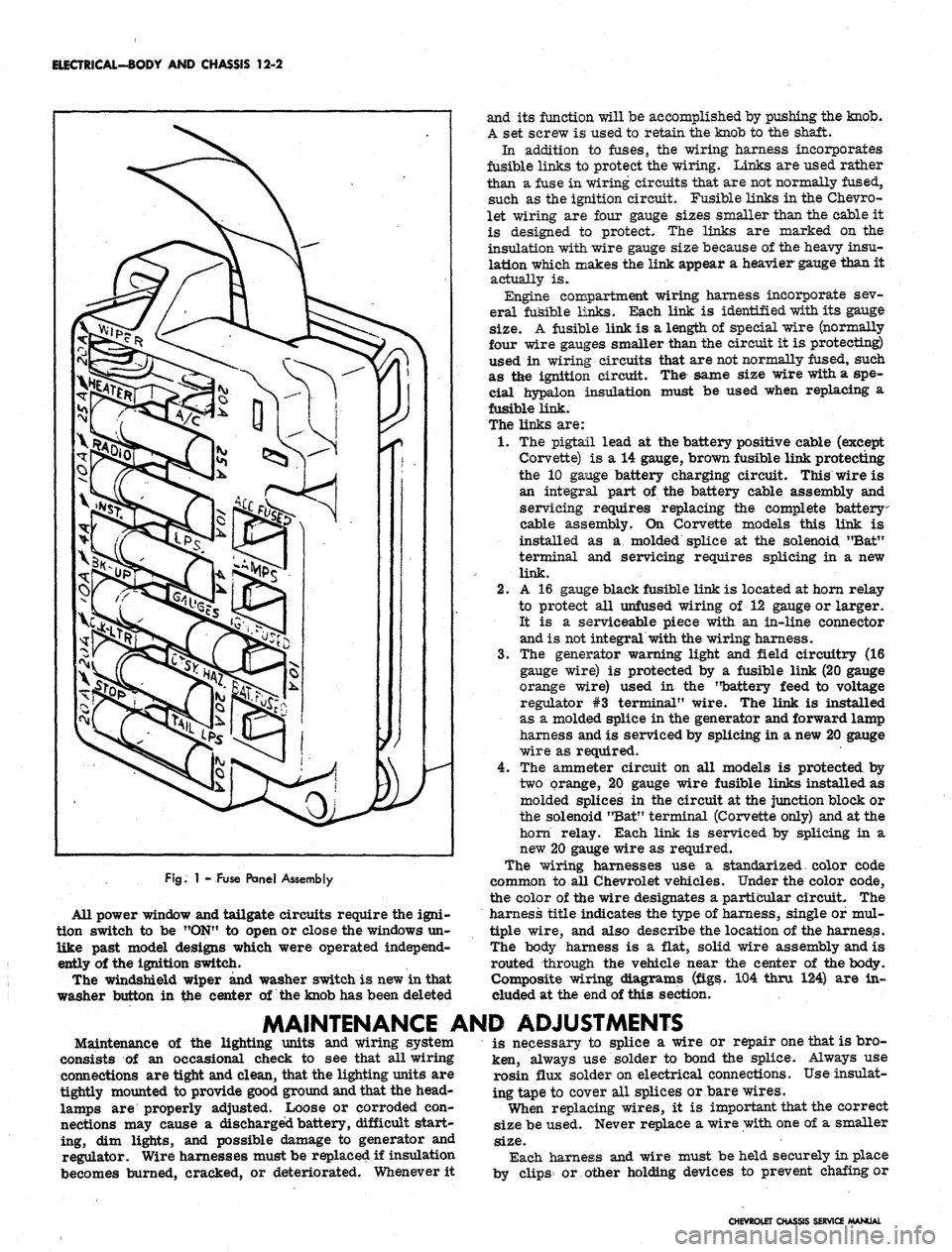
necessary wiring to complete the various circuits. A
fuse panel provides convenient power take offs and fuse
clips for the appropriate circuits (fig. 1).
Chevrolet and Chevelle headlamp installation is all
new in that the headlamps are located in the radiator
support with adjusting screws and springs. Eliminating
the need for having separate headlamp housings. Chev-
rolet and Chevelle headlamp retainers and springs are
interchangeable.
Chevy n headlamp housings are new because of revised
front end styling and Corvette front end lighting is basi-
cally carryover.
Front fender lamps have been added as an option for
Chevrolet models and as standard equipment on Caprice
series.
Camaro models use single headlamps and the Rally
Sport model headlamps are covered by a retractable
section of the grille when lamps are not used. The sec-
tion of the grille covering the headlamps folds back when
lights are required; the headlamps are stationary. The
covering is retracted by a small electric motor mounted
to the headlamp housing. The headlamps are automat-
ically uncovered when the headlight switch is pulled "ON"
for illumination. If at any time the electrical circuit
becomes inoperative, the lamps can be uncovered manu-
ally. The ignition switch must be
"ON"
in order to close
the headlamp doors.
Parking lamp for Chevelle and Chevrolet models are
new due to revised front end sheet metal and bumper
styling. Parking lamps are located in the bumper on
Chevrolet, Chevelle and Chevy n models
Camaro parking lamps are located in the radiator
grille except for the Rally Sport models on which the
parking lamps are in the valance panel. For styling
reasons, the lens is white and an amber glass bulb is
used. All Camaro parking lamps require a separate
ground wire to assure a good ground contact because of
the plastic grille and painted contact surfaces.
The Chevrolet tail, stop, and directional lamps are in
one housing with a three section lens design on Impala
and Caprice sedans. The center lens for Impala series
is the back-up lamp. The center lens on the Caprice is
a tail lamp with the back-up lamps being located in the
rear bumper. Chevrolet station wagons have three indi-
vidual housings with three lenses, the center lamp being
the back-up. Biscayne and Bel-Air sedans have a single
housing and lens for tail, stop, and directional lamp with
a similarly constructed back-up lamp inboard and adja-
cent to it.
Chevelle tail, stop, and directional lamps are a single
lens design that follows through with the rear fender
styling. The back-up lamp is located in r.ear bumper.
Camaro models except Rally Sport have tail lamps
with integral back-up lamps mounted inboard of the rear
fenders between the trunk opening and bumper. The
Rally Sport model has dual tail lamps in the rear housing
and valance mounted back-up lamps.
Corvette, Chevy n, and Corvair tail and directional
signal lights are carryover. The Corvette has new back-
up lamps center mounted above the license plate opening.
CHEVROLET CHASSIS SERVICE
Page 514 of 659
ELECTRICAL-BODY AND CHASSIS 12-2
FJg.
1 - Fuse Panel Assembly
All power window and tailgate circuits require the igni-
tion switch to be "ON" to open or close the windows un-
like past model designs which were operated independ-
ently of the ignition switch.
The windshield wiper and washer switch is new in that
washer button in the center of the knob has been deleted
and its function will be accomplished by pushing the knob.
A set screw is used to retain the knob to the shaft.
In addition to fuses, the wiring harness incorporates
fusible links to protect the wiring. Links are used rather
than a fuse in wiring circuits that are not normally fused,
such as the ignition circuit. Fusible links in the Chevro-
let wiring are four gauge sizes smaller than the cable it
is designed to protect. The links are marked on the
insulation with wire gauge size because of the heavy insu-
lation which makes the link appear a heavier gauge than it
actually is.
Engine compartment wiring harness incorporate sev-
eral fusible links. Each link is identified with its gauge
size.
A fusible link is a length of special wire (normally
four wire gauges smaller than the circuit it is protecting)
used in wiring circuits that are not normally fused, such
as the ignition circuit. The same size wire with a spe-
cial hypalon insulation must be used when replacing a
fusible link.
The links are:
1.
The pigtail lead at the battery positive cable (except
Corvette) is a 14 gauge, brown fusible link protecting
the 10 gange battery charging circuit. This wire is
an integral part of the battery cable assembly and
servicing requires replacing the complete battery
cable assembly. On Corvette models this link is
installed as a molded splice at the solenoid "Bat"
terminal and servicing requires splicing in a new
link.
2.
A 16 gauge black fusible link is located at horn relay
to protect all unfused wiring of 12 gauge or larger.
It is a serviceable piece with an in-line connector
and is not integral with the wiring harness.
3.
The generator warning light and field circuitry (16
gauge wire) is protected by a fusible link (20 gauge
orange wire) used in the "battery feed to voltage
regulator #3 terminal" wire. The link is installed
as a molded splice in the generator and forward lamp
harness and is serviced by splicing in a new 20 gauge
wire as required.
4.
The ammeter circuit on all models is protected by
two orange, 20 gauge wire fusible links installed as
molded splices in the circuit at the junction block or
the solenoid "Bat" terminal (Corvette only) and at the
horn relay. Each link is serviced by splicing in a
new 20 gauge wire as required.
The wiring harnesses use a standarized. color code
common to all Chevrolet vehicles. Under the color code,
the color of the wire designates a particular circuit. The
harness title indicates the type of harness, single of mul-
tiple wire, and also describe the location of the harness.
The body harness is a flat, solid wire assembly and is
routed through the vehicle near the center of the body.
Composite wiring diagrams (figs. 104 thru 124) are in-
cluded at the end of this section.
MAINTENANCE AND ADJUSTMENTS
Maintenance of the lighting units and wiring system
consists of an occasional check to see that all wiring
connections are tight and clean, that the lighting units are
tightly mounted to provide good ground and that the head-
lamps are properly adjusted. Loose or corroded con-
nections may cause a discharged battery, difficult start-
ing, dim lights, and possible damage to generator and
regulator. Wire harnesses must be replaced if insulation
becomes burned, cracked, or deteriorated. Whenever it
is necessary to splice a wire or repair one that is bro-
ken, always use solder to bond the splice. Always use
rosin flux solder on electrical connections. Use insulat-
ing tape to cover all splices or bare wires.
When replacing wires, it is important that the correct
size be used. Never replace a wire with one of a smaller
size.
Each harness and wire must be held securely in place
by clips or other holding devices to prevent chafing or
CHEVROLET CHASSIS SERVICE MANUAL