wheel bolts CHEVROLET CAMARO 1967 1.G Chassis User Guide
[x] Cancel search | Manufacturer: CHEVROLET, Model Year: 1967, Model line: CAMARO, Model: CHEVROLET CAMARO 1967 1.GPages: 659, PDF Size: 114.24 MB
Page 180 of 659
FRONT SUSPENSION 3-16
available the following procedure may also be
used (fig. 22-Alternate Method).
1.
Support car on suitable hoist or jack (so control
arms may swing free) and remove the wheel and
tire assembly, shock absorber, and stabilizer link
at control arm.
2.
Place suitable jack stand under the lower control
arm cross shaft.
3.
Follow Steps 2-5 as outlined on previous page.
4.
Turn head of tool screw to partially compress
spring.
5. Remove the three control arm cross shaft attaching
bolts,
washers and nuts.
6. Carefully lower jack stand and if necessary increase
compression on spring and when coil spring is out of
its upper seat, relax tension on spring (fig. 22).
7. By using a pry bar to assist, if necessary, remove
the coil spring from the lower control arm.
8. Installation is the reverse of the above procedure.
Carefully follow instructions for installing spring
tool.
LOWER CONTROL ARM SPHERICAL JOINT
Chevrolet, Chevelle, Comoro and Corvette
Inspection
The lower control arm spherical joint should be re-
placed whenever wear is indicated in the upper joint
inspection.
NOTE: The lower control arm spherical joint
is a loose fit in the assembly when not connected
to the steering knuckle.
Only if inspection of each upper joint indicates them
both to be within limits, inspect each lower joint for ex-
cessive wear as follows:
1.
After reconnecting upper joints to steering knuckles,
support vehicle weight on wheels or wheel hubs.
2.
With outside micrometer or caliper, measure dis-
tance from top of lubrication fitting to bottom of ball
stud, and record the dimensions for each side.
3.
Then support vehicle weight at outer end of each
lower control arm, so that wheels or wheel hubs are
free,
then repeat Step 2.
4.
If the difference in dimensions on either side is
greater than 1/16" (.0625"), the joint is excessively
worn and both lower joints should be replaced.
If inspection of lower spherical joints does not indicate
excessive wear, inspect further as follows:
5.
On Chevrolet Only--Examine lubrication hole in each
joint assembly after cleaning out hole. Look for evi-
dence of the liner partially or fully blocking lubrica-
tion opening. Such evidence indicates that liner is
disintegrating and that both lower spherical joints
should be replaced.
Another indication of lower spherical joint excessive
wear is indicated when difficulty is experienced when
lubricating the joint. If the liner has worn to the point
where the lubrication grooves in the liner have worn
away, then abnormal pressure is required to force lubri-
cant through the joint. This is another reason to recom-
mend replacement of both lower joints.
If the above inspections do not indicate any reason for
spherical joint replacements, test the torque tightness of
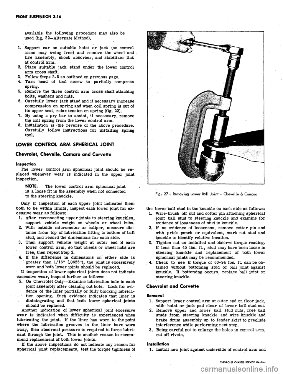
Fig. 27 - Removing Lower Ball Joint - Chevelle
&
Camaro
the lower ball stud in the knuckle on each side as follows:
1.
Wire-brush off nut and cotter pin attaching spherical
joint ball stud to steering knuckle and examine for
evidence of looseness of stud in knuckle.
2.
If no evidence of looseness, remove cotter pin and
with prick punch or equivalent, mark nut stud and
knuckle to identify relative location.
3.
Tighten nut as installed and observe torque reading.
If less than 45 lbs. ft., stud may have been loose in
steering knuckle and replacement of both lower
spherical joints may be recommended.
4.
Check to see if torque of 60-94 lbs. ft. can be ob-
tained without bottoming stud or ball joint against
knuckle. If bottoming occurs, replace ball joint or
steering knuckle.
Chevrolet and Corvette
Removal
1.
Support lower control arm at outer end on floor jack,
with hoist or jack pad clear of lower ball stud nut.
2.
Remove upper and lower ball stud nuts, free ball
studs from steering knuckle and wire knuckle and
brake drum assembly up to fender skirt to preclude
interference while performing next step.
3.
Being careful not to enlarge the holes in control arm,
cut off rivets.
Installation
1.
Install new joint against underside of control arm and
CHEVROLET CHASSIS SERVICE MANUAL
Page 181 of 659
FRONT SUSPENSION 3-17
4.
Replace the wheel and tire.
5.
Lower the vehicle.
Chevy II
inspection
Fig.
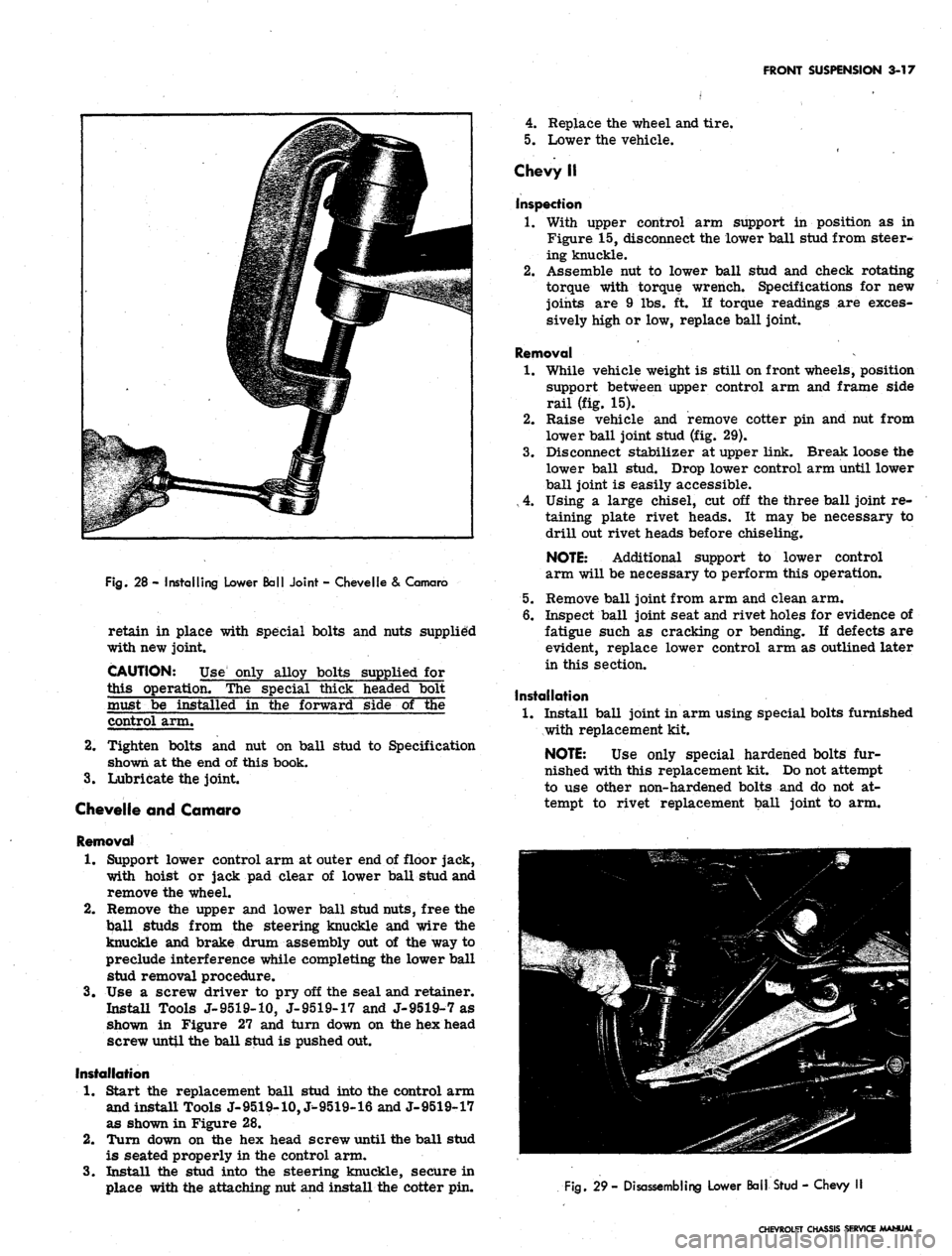
28 - Installing Lower Ball Joint - Chevelle & Camaro
retain in place with special bolts and nuts supplied
with new joint.
CAUTION: Use only alloy bolts supplied for
this operation. The special thick headed bolt
must be installed in the forward side of the
control arm.
2.
Tighten bolts and nut on ball stud to Specification
shown at the end of this book.
3.
Lubricate the joint.
Chevelle and Camaro
Removal
1.
Support lower control arm at outer end of floor jack,
with hoist or jack pad clear of lower ball stud and
remove the wheel.
2.
Remove the upper and lower ball stud nuts, free the
ball studs from the steering knuckle and wire the
knuckle and brake drum assembly out of the way to
preclude interference while completing the lower ball
stud removal procedure.
3.
Use a screw driver to pry off the seal and retainer.
Install Tools J-9519-10, J-9519-17 and J-9519-7 as
shown in Figure 27 and turn down on the hex head
screw until the ball stud is pushed out.
Installation
1.
Start the replacement ball stud into the control arm
and install Tools J-9519-10, J^9519-16 and J-9519-17
as shown in Figure 28.
2.
Turn down on the hex head screw until the ball stud
is seated properly in the control arm.
3.
Install the stud into the steering knuckle, secure in
place with the attacking nut and install the cotter pin.
1.
With upper control arm support in position as in
Figure 15, disconnect the lower ball stud from steer-
ing knuckle.
2.
Assemble nut to lower ball stud and check rotating
torque with torque wrench. Specifications for new
joints are 9 lbs. ft. If torque readings are exces-
sively high or low, replace ball joint.
Removal
1.
While vehicle weight is still on front wheels, position
support between upper control arm and frame side
rail (fig. 15).
2.
Raise vehicle and remove cotter pin and nut from
lower ball joint stud (fig. 29).
3.
Disconnect stabilizer at upper link. Break loose the
lower ball stud. Drop lower control arm until lower
ball joint is easily accessible.
, 4. Using a large chisel, cut off the three ball joint re-
taining plate rivet heads. It may be necessary to
drill out rivet heads before chiseling.
NOTE: Additional support to lower control
arm will be necessary to perform this operation.
5.
Remove ball joint from arm and clean arm.
6. Inspect ball joint seat and rivet holes for evidence of
fatigue such as cracking or bending. If defects are
evident, replace lower control arm as outlined later
in this section.
Installation
1.
Install ball joint in arm using special bolts furnished
with replacement kit.
NOTE: Use only special hardened bolts fur-
nished with this replacement kit. Do not attempt
to use other non-hardened bolts and do not at-
tempt to rivet replacement ball joint to arm.
Fig.
29- Disassembling Lower Ball Stud - Chevy
CHEVROLET CHASSIS SERVICE MANUAL
Page 182 of 659
FRONT SUSPENSION 3-18
CHEVROLET
CHEVELLE
CAMARO (TYPICAL)
CHEVY U
LOWER CONTROL ARM
CORVETTE
Fig.
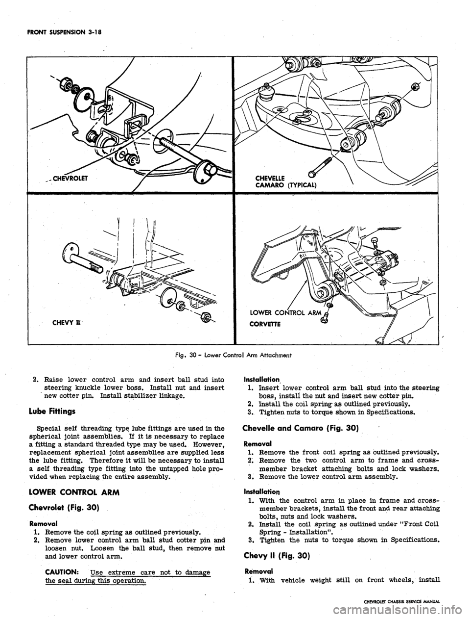
30 - Lower Control Arm Attachment
2.
Raise lower control arm and insert ball stud into
steering knuckle lower boss. Install nut and insert
new cotter pin. Install stabilizer linkage.
Lube Fittings
Special self threading type lube fittings are used in the
spherical joint assemblies. If it is necessary to replace
a fitting a standard threaded type may be used. However,
replacement spherical joint assemblies are supplied less
the lube fitting. Therefore it will be necessary to install
a self threading type fitting into the untapped hole pro-
vided when replacing the entire assembly.
LOWER CONTROL ARM
Chevrolet (Fig. 30)
Removal
1.
Remove the coil spring as outlined previously.
2.
Remove lower control arm ball stud cotter pin and
loosen nut. Loosen the ball stud, then remove nut
and lower control arm.
CAUTION: Use extreme care not to damage
the seal during this operation.
Installation
1.
Insert lower control arm ball stud into the steering
boss,
install the nut and insert new cotter pin.
2.
Install the coil spring as outlined previously.
3.
Tighten nuts to torque shown in Specifications.
Chevelle and Camaro (Fig. 30)
Removal
1.
Remove the front coil spring as outlined previously.
2;
Remove the two control arm to frame and cross-
member bracket attaching bolts and lock washers.
3.
Remove the lower control arm assembly.
Installation
1.
With the control arm in place in frame and cross-
member brackets, install the front and rear attaching
bolts,
nuts and lock washers.
2.
Install the coil spring as outlined under "Front Coil
Spring - Installation".
3.
Tighten the nuts to torque shown in Specifications.
Chevy II (Fig. 30)
Removal
1.
With vehicle weight still on front wheels, install
CHEVROLET CHASSIS SERVICE MANUAL
Page 185 of 659
FRONT SUSPENSION 3-21
Chevy II
Removal
1.
Support control arm on Tool J-7 574-4 and insert
Spacer J-9514 (fig. 34).
2,
Press bushing out with Tool J-9226 and Handle
J-7079-2 (fig. 34).
Installation
With Spacer J-9514 still in control arm, invert control
arm and press in new bushing with Tool, J-7474-2 and
Handle J-7079-2 until bushing is fully seated.
CAUTION: It should be noted that control arm
bushing diameters are unequal and bushing must
be pressed into position through larger diameter
only.
CROSS SHAFT AND/ON BUSHINGS
Corvette
Removal
1.
Remove bolt, lock washer and collar from each end
of cross shaft.
2.
Thread a 7/16 x 20 capscrew (furnished with Tool
J-5888) to the bottom of the threads in one end of the
cross shaft.
3.
Support control arm in an arbor press on Tool
J-5888-3,
as shown in Figure 35.
NOTE:
Be certain bushing flange does not
contact support.
4.
Press on cap screw until bushing is free of control
arm. Discard bushing.
5. Remove cap screw from cross shaft. Insert it in
other end of shaft. Invert control arm on support.
Again be certain bushing flange does not contact
support.
6. Press on cap screw until bushing is free of control
arm. Discard bushing.
Installation
1.
With cross shaft in control arm and Tool J-7052-1
in position, place control arm on Tool J-5888-3.
Hand start bushing into control arm and over end of
cross shaft.
NOTE:
The end of the shaft with the two bolt
holes should be toward front of control arm.
2.
Install Tool J-7052-5 over bushing. Be certain
three-piece spacer is not over-lapping bushing holes
in control arm.
3.
Press bushing into control arm until flange contacts
control arm (fig. 36).
4.
Invert arm in press and repeat the process on the
other bushing. After installation, cross shaft should
be free enough to be rotated by hand.
5. Install collar, lock washer and cap screw in each end
of cross shaft. Tighten to torque shown in Specifica-
tions after spring installation.
UPPER CONTROL ARM SPHERICAL JOINT
Chevrolet, Chevelle, Comoro and Corvette
Inspection
The upper spherical joint is checked for wear by
checking the torque required to rotate the ball stud in the
assembly. After performing the first four steps under
"Replacement" below, install a stud nut on the stud and
measure the torque required to turn the stud in the as-
sembly with a torque wrench. Specified torque for a new
joint is 9 lbs. ft. If torque readings are excessively
high or low, replace the ball joint. If excessive wear is
indicated in upper joint, both upper and lower joints
should be replaced.
NOTE:
This inspection does not necessitate
upper control arm removal.
Replacement
1.
Support the vehicle weight at the outer end of the
lower control arm.
2.
Remove the wheel and tire assembly.
3.
Remove cotter pin and nut from upper control arm
ball stud.
4.
Remove the stud from knuckle.
5. Cut off the ball joint rivets with a chisel.
6. Install new joint and retain in place with the special
nuts and bolts supplied.
7. Reassemble ball stud to the steering knuckle.
Chevy II
Inspection
The following on-the-vehicle check is to determine ball
joint wear.
NOTE:
The upper ball joint is a loose fit when
not connected to the steering knuckle. Wear may
be checked without disassembling the ball stud
by
using'
the following procedure:
1.
While vehicle weight is still on front wheels, insert
upper control arm support as shown in Figure 14.
2.
Raise vehicle and allow wheel and tire to hang free.
3.
Measure distance from tip of ball stud to top surface
of control arm.
4.
Place adjustable jackstand under tire and raise
slightly to take up ball joint looseness.
5. Repeat Step 3 and if the difference in measurements
exceeds 3/32", the joint is excessively worn and
should be replaced.
Replacement
1.
With vehicle weight still on front wheels, install
spacer between upper control arm and frame side
rail (fig. 15). Raise vehicle.
2.
Remove wheel and tire.
3.
Disconnect stabilizer link (if present) and strut rod
at lower control arm.
4.
Remove cotter pin and nut from upper ball joint stud.
5. Break ball stud loose. Drop lower control arm,
steering knuckle and brake assembly with an adjust-
able jackstand until upper control arm ball joint is
easily accessible.
6. Using a large chisel, cut off the three ball joint re-
taining plate rivet heads. It may be necessary to
drill out rivet heads before chiseling.
CHEVROLET CHASSIS SERVICE MANUAL
Page 186 of 659

FRONT SUSPENSION
3-22
CHEVROLET
s-L 1 \
TYPICAL
OF
-^-x ^K CORVETTE, CHEVELLE AND CAMARO
CHEVY n
Rg.
37 - Upper Control Arm Attachment
NOTE:
Additional support to upper control
arm may be necessary while chiseling.
7. Clean ball joint seat in arm and inspect for cracking
or other evidence of fatigue. If cracks are present at
the rivet holes or ball joint opening, replace arm as
outlined later in this section.
8. Attach replacement ball joint assembly to the control
arm, using special bolts furnished with replacement
kit.
NOTE:
Use only special hardened bolts fur-
nished with this replacement kit. Do not attempt
to use other non-hardened bolts and do not at-
tempt to rivet replacement ball joint to arm.
9. Raise lower control arm and steering knuckle as-
sembly into position, insert upper ball stud into up-
per steering knuckle and install stud nut. Torque
nut as shown in the specifications and insert new
cotter pin. Install stabilizer and strut rod.
10.
Lubricate ball joint, install wheel and tire and re-
move adjustable jackstand.
11.
Lower vehicle and remove upper control arm spacer.
12.
Check and readjust caster and camber angles where
necessary.
LUBE FITTINGS
Special self threading type lube fittings are used in the
spherical joint assemblies. If it is necessary to replace
a fitting a standard threaded type may be used. However,
replacement spherical joint assemblies are supplied less
the lube fitting. Therefore it will be necessary to install
a self threading type fitting into the untapped hole pro-
vided when replacing the entire assembly.
UPPER CONTROL ARM
Chevrolet, Chevelle, Camaro and Corvette
(Fig.
37)
Removal
1.
Support vehicle weight at outer end of lower control
arm.
2.
Remove wheel and tire assembly.
3.
Remove cotter pin and nut from upper control arm
ball stud. ,
4.
REMOVE The stud from knuckle.
5. Remove two nuts retaining upper control arm shaft to
front crossmember. (Chevelle, Camaro and Cor-
vette—Note number of shims at each bolt.)
6. Remove the bolts attaching the control arm to the
frame to allow proper clearance for control arm
removal if necessary.
7. Remove upper control arm from vehicle.
Installation
1.
Install upper control arm in vehicle.
2.
Install nuts, bolts and lock washers retaining upper
control arm shaft to frame. (Chevelle, Camaro and
Corvette—Install same number of shims as removed
at each bolt.)
3.
Torque nuts as shown in the Specifications at the end
of this book.
4.
Install ball stud through knuckle, install nut, tighten
and install cotter pin.
5. Install wheel and tire assembly.
6. Lower vehicle to floor.
7. Bounce front end of vehicle to centralize bushings
and tighten bushing collar bolts as shown in the
Specifications.
Chevy II (Fig. 37)
Removal
1.
Remove spring and shock absorber as outlined above.
2.
Position adjustable jackstand under lower control
arm.
3.
Remove cotter pin and nut from upper ball joint stud
and strike steering knuckle boss to loosen stud.
4.
Drop lower control arm and steering knuckle
assembly.
CHEVROLET CHASSIS SERVICE MANUAL
Page 194 of 659
REAR SUSPENSION AND DRIVE LINE
4-4
PROPELLER SHAFT
CARRIER FRONT SUPPORT
CAMBER CAM CONTROL ARM
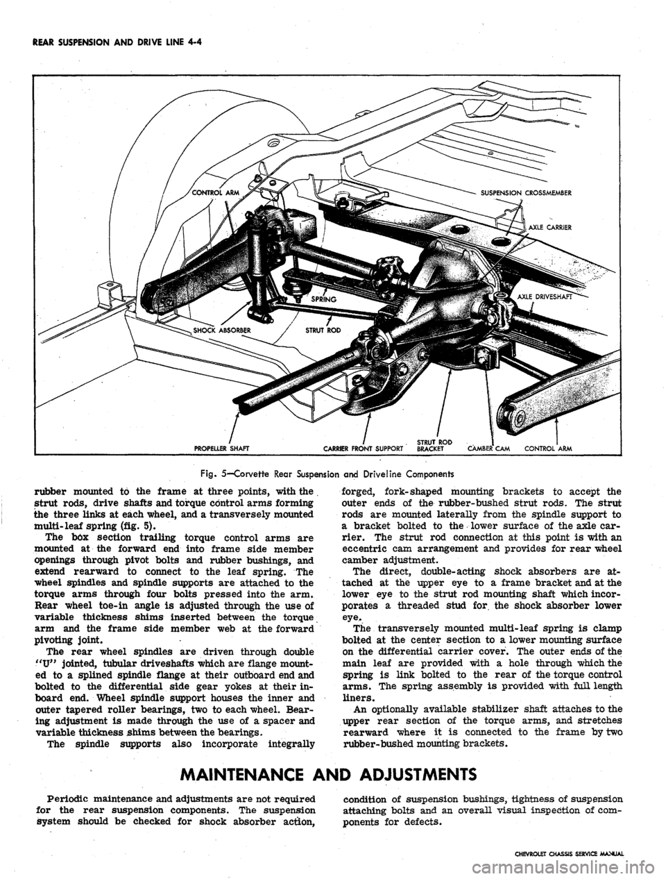
Fig. 5—Corvette Rear Suspension and Driveline Components
rubber mounted to the frame at three points, with the .
strut rods, drive shafts and torque control arms forming
the three links at each wheel, and a transversely mounted
multi-leaf spring (fig. 5).
The bbx section trailing torque control arms are
mounted at the forward end into frame side member
openings through pivot bolts and rubber bushings, and
extend rearward to connect to the leaf spring. The
wheel spindles and spindle supports are attached to the
torque arms through four bolts pressed into the arm.
Rear wheel toe-in angle is adjusted through the use of
variable thickness shims inserted between the torque
arm and the frame side member web at the forward
pivoting joint.
The rear wheel spindles are driven through double
"U"
jointed, tubular driveshafts which are flange mount-
ed to a splined spindle flange at their outboard end and
bolted to the differential side gear yokes at their in-
board end. Wheel spindle support houses the inner and
outer tapered roller bearings, two to each wheel. Bear-
ing adjustment is made through the use of a spacer and
variable thickness shims between the bearings.
The spindle supports also incorporate integrally
forged, fork-shaped mounting brackets to accept the
outer ends of the rubber-bushed strut rods. The strut
rods are mounted laterally from the spindle support to
a bracket bolted to the lower surface of the axle car-
rier. The strut rod connection at this point is with an
eccentric cam arrangement and provides for rear wheel
camber adjustment.
The direct, double-acting shock absorbers are at-
tached at the upper eye to a frame bracket and at the
lower eye to the strut rod mounting shaft which incor-
porates a threaded stud for. the shock absorber lower
eye.
The transversely mounted multi-leaf spring is clamp
bolted at the center section to a lower mounting surface
on the differential carrier cover. The outer ends of the
main leaf are provided with a hole through which the
spring is link bolted to the rear of the torque control
arms.
The spring assembly is provided with full length
liners.
An optionally available stabilizer shaft attaches to the
upper rear section of the torque arms, and stretches
rearward where it is connected to the frame by two
rubber-bushed mounting brackets.
MAINTENANCE AND ADJUSTMENTS
Periodic maintenance and adjustments are not required
for the rear suspension components. The suspension
system should be checked for shock absorber action,
condition of suspension bushings, tightness of suspension
attaching bolts and an overall visual inspection of com-
ponents for defects.
CHEVROLET CHASSIS SERVICE MANUAL
Page 202 of 659
REAR SUSPENSION AND DRIVE LINE 4-12
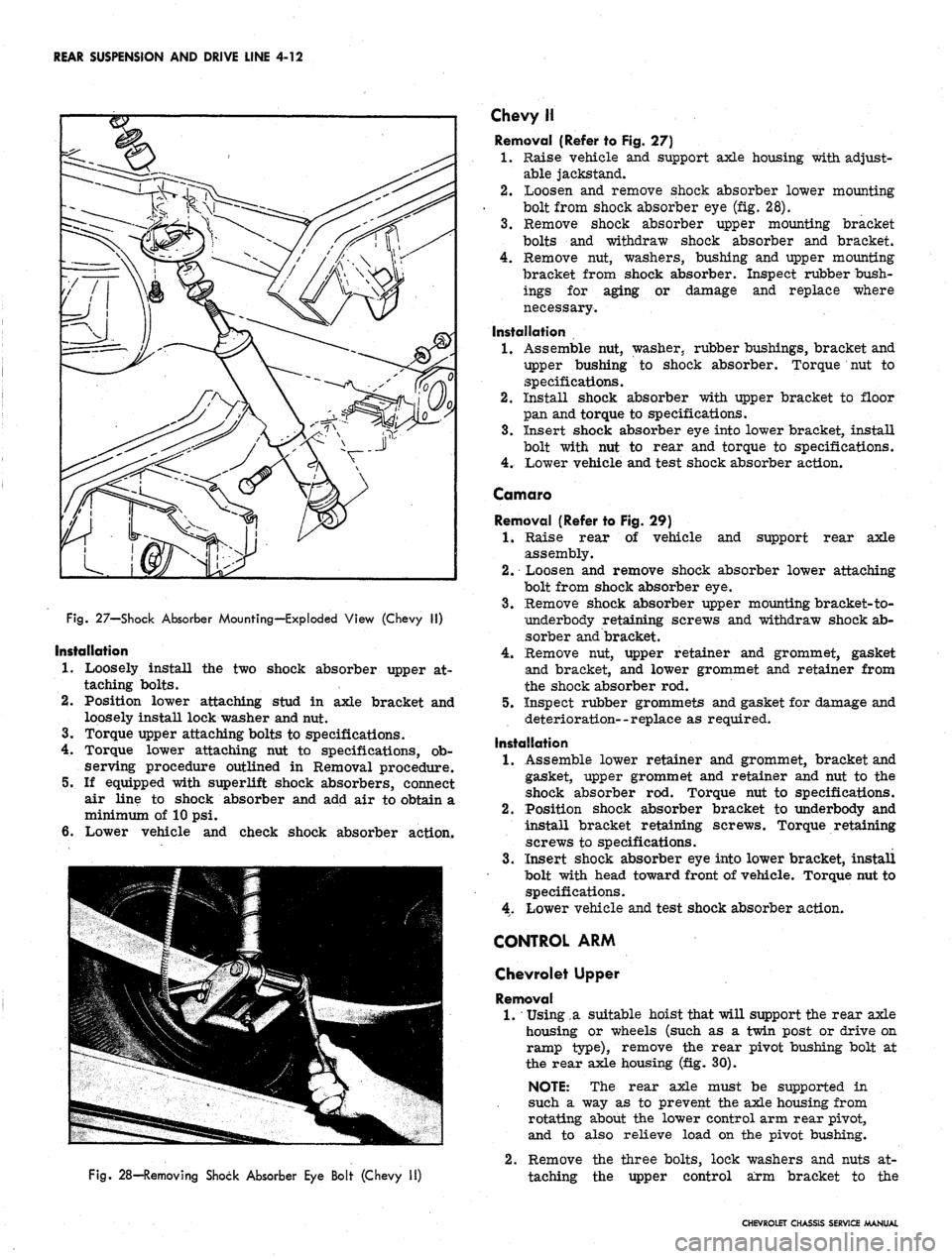
Fig.
27—Shock Absorber Mounting—Exploded View (Chevy II)
Installation
1.
Loosely install the two shock absorber upper at-
taching bolts.
2.
Position lower attaching stud in axle bracket and
loosely install lock washer and nut.
3.
Torque upper attaching bolts to specifications.
4.
Torque lower attaching nut to specifications, ob-
serving procedure outlined in Removal procedure.
5.
If equipped with superlift shock absorbers, connect
air line to shock absorber and add air to obtain a
minimum of 10 psi.
6. Lower vehicle and check shock absorber action.
Fig.
28—Removing Shock Absorber Eye Bolt (Chevy II)
Chevy H
Removal (Refer to Fig. 27)
1.
Raise vehicle and support axle housing with adjust-
able jackstand.
2.
Loosen and remove shock absorber lower mounting
bolt from shock absorber eye (fig. 28).
3.
Remove shock absorber upper mounting bracket
bolts and withdraw shock absorber and bracket.
4.
Remove nut, washers, bushing and upper mounting
bracket from shock absorber. Inspect rubber bush-
ings for aging or damage and replace where
necessary.
Installation
1.
Assemble nut, washer, rubber bushings, bracket and
upper bushing to shock absorber. Torque nut to
specifications.
2.
Install shock absorber with upper bracket to floor
pan and torque to specifications.
3.
Insert shock absorber eye into lower bracket, install
bolt with nut to rear and torque to specifications.
4.
Lower vehicle and test shock absorber action.
Comoro
Removal (Refer to Fig. 29)
1.
Raise rear of vehicle and support rear axle
assembly.
2.
Loosen and remove shock absorber lower attaching
bolt from shock absorber eye.
3.
Remove shock absorber upper mounting bracket-to-
iiinderbody retaining screws and withdraw shock ab-
sorber and bracket.
4.
Remove nut, upper retainer and grommet, gasket
and bracket, and lower grommet and retainer from
the shock absorber rod.
5.
Inspect rubber grommets and gasket for damage and
deterioration--replace as required.
Installation
1.
Assemble lower retainer and grommet, bracket and
gasket, upper grommet and retainer and nut to the
shock absorber rod. Torque nut to specifications.
2.
Position shock absorber bracket to underbody and
install bracket retaining screws. Torque retaining
screws to specifications.
3.
Insert shock absorber eye into lower bracket, install
bolt with head toward front of vehicle. Torque nut to
specifications.
4.
Lower vehicle and test shock absorber action.
CONTROL ARM
Chevrolet Upper
Removal
1.
*
Using,a suitable hoist that will support the rear axle
housing or wheels (such as a twin post or drive on
ramp type), remove the rear pivot bushing bolt at
the rear axle housing (fig. 30).
NOTE: The rear axle must be supported in
such a way as to prevent the axle housing from
rotating about the lower control arm rear pivot,
and to also relieve load on the pivot bushing.
2.
Remove the three bolts, lock washers and nuts at-
taching the upper control arm bracket to the
CHEVROLET CHASSIS SERVICE MANUAL
Page 210 of 659
REAR SUSPENSION AND DRIVE LINE 4-20
Fig.
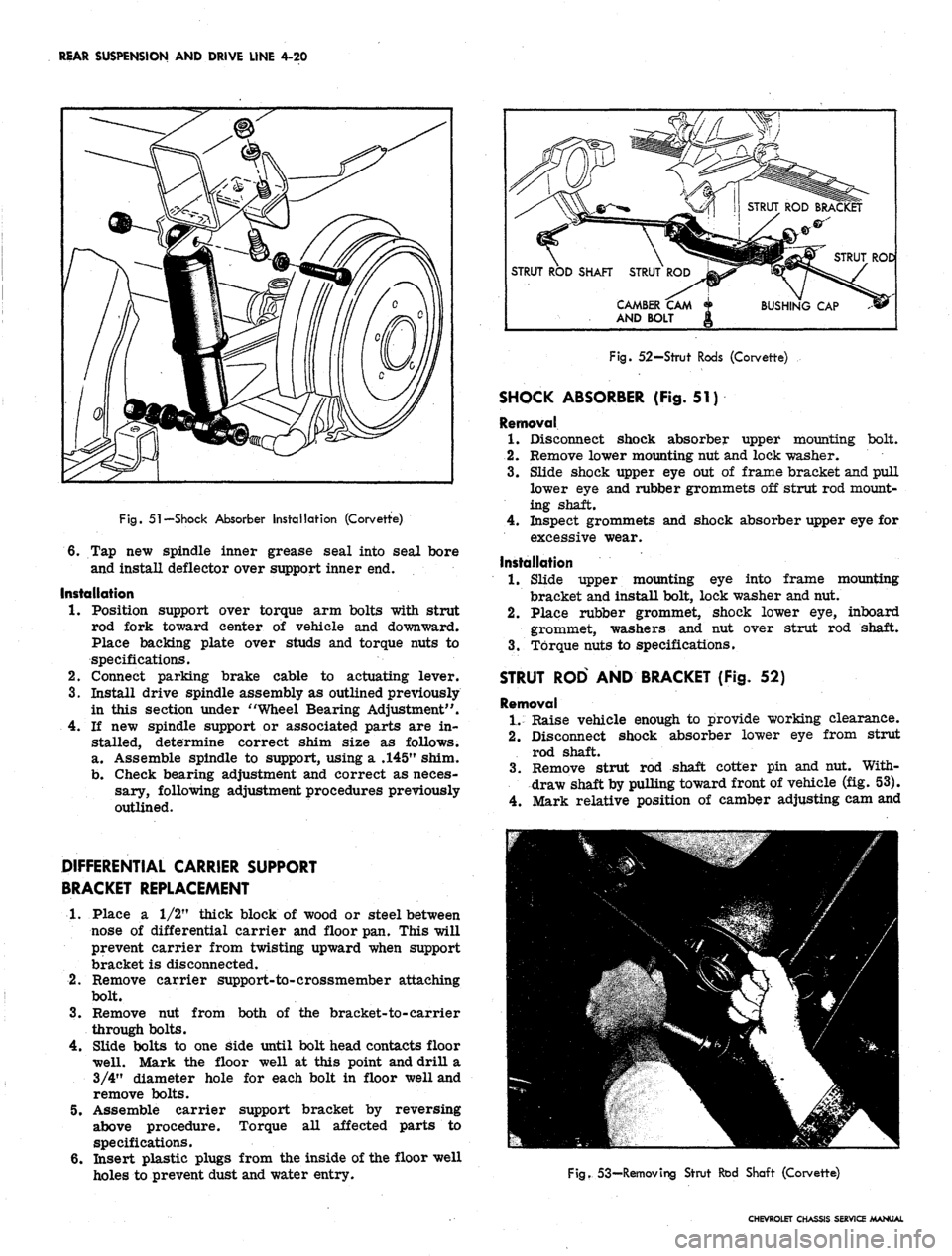
51—Shock Absorber Installation (Corvette)
6. Tap new spindle inner grease seal into seal bore
and install deflector over support inner end.
Installation
1.
Position support over torque arm bolts with strut
rod fork toward center of vehicle and downward.
Place backing plate over studs and torque nuts to
specifications.
2.
Connect parking brake cable to actuating lever.
3.
Install drive spindle assembly as outlined previously
in this section under "Wheel Bearing Adjustment".
4.
If new spindle support or associated parts are in-
stalled, determine correct shim size as follows.
a. Assemble spindle to support, using a .145" shim.
b.
Check bearing adjustment and correct as neces-
sary, following adjustment procedures previously
outlined.
DIFFERENTIAL CARRIER SUPPORT
BRACKET REPLACEMENT
1.
Place a 1/2" thick block of wood or steel between
nose of differential carrier and floor pan. This will
prevent carrier from twisting upward when support
bracket is disconnected.
2.
Remove carrier support-to-crossmember attaching
bolt.
3.
Remove nut from both of the bracket-to-carrier
through bolts.
4.
Slide bolts to one side until bolt head contacts floor
well. Mark the floor well at this point and drill a
3/4"
diameter hole for each bolt in floor well and
remove bolts.
5. Assemble carrier support bracket by reversing
above procedure. Torque all affected parts to
specifications.
6. Insert plastic plugs from the inside of the floor well
holes to prevent dust and water entry.
STRUT ROD SHAFT STRUT ROD
CAMBER CAM
AND BOLT
Fig.
52—Strut Rods (Corvette)
SHOCK ABSORBER (Fig. 51)
Removal
1.
Disconnect shock absorber upper mounting bolt*
2.
Remove lower mounting nut and lock washer.
3.
Slide shock upper eye out of frame bracket and pull
lower eye and rubber grommets off strut rod mount-
ing shaft.
4.
Inspect grommets and shock absorber upper eye for
excessive wear.
Installation
1.
Slide upper mounting eye into frame mounting
bracket and install bolt, lock washer and nut.
2.
Place rubber grommet, shock lower eye, inboard
grommet, washers and nut over strut rod shaft.
3.
Torque nuts to specifications.
STRUT ROD AND BRACKET (Fig. 52)
Removal
1.
Raise vehicle enough to provide working clearance.
2.
Disconnect shock absorber lower eye from strut
rod shaft.
3.
Remove strut rod shaft cotter pin and nut. With-
draw shaft by pulling toward front of vehicle (fig. 53).
4.
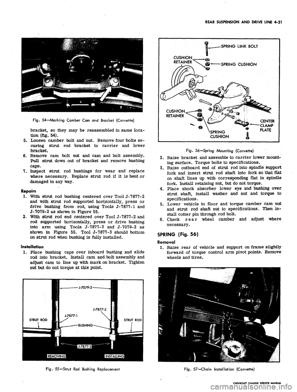
Mark relative position of camber adjusting cam and
Fig.
53-Removing Strut Rod Shaft (Corvette)
CHEVROLET CHASSIS SERVICE MANUAL
Page 211 of 659
REAR SUSPENSION AND DRIVE LINE 4-21
Fig.
54—Marking Camber Cam and Bracket (Corvette)
bracket, so they may be reassembled in same loca-
tion (fig. 54).
5.
Loosen camber bolt and nut. Remove four bolts se-
curing strut rod bracket to carrier and lower
bracket.
6. Remove cam bolt nut and cam and bolt assembly.
Pull strut down out of bracket and remove bushing
caps.
7.
Inspect strut rod bushings for wear and replace
where necessary. Replace strut rod if it is bent or
damaged in any way.
Repairs
1.
With strut rod bushing centered over Tool J-7877-2
and with strut rod supported horizontally, press or
drive bushing from rod, using Tools J-7877-i and
J-7079-2 as shown in Figure 55.
2.
With strut rod end centered over Tool J-7877-2 and
rod supported horizontally, press or drive bushing
into arm using Tools J-7877-3 and J-7079-2 as
shown in Figure 55. Tool J-7877-3 should bottom
on strut rod when bushing is fully installed.
Installation
1.
Place bushing caps over inboard bushing and slide
rod into bracket. Install cam and bolt assembly and
adjust cam to line up with mark on bracket. Tighten
nut but do not torque at this point.
SPRING
LINK BOLT
SPRING
CUSHION
SPRING
CUSHION
CENTER
CLAMP
PLATE
J-7877-3
J-7877-1
STRUT ROD 11 s* ^#3 STRUT ROD
BUSHING
Fig.
56—Spring Mounting (Corvette)
2.
Raise bracket and assemble to carrier lower mount-
ing surface. Torque bolts to specifications.
3.
Raise outboard end of strut rod into spindle support
fork and insert strut rod shaft into fork so that flat
on shaft lines up with corresponding flat in spindle
fork. Install retaining nut, but do not torque.
4.
Place shock absorber lower eye and bushing over
strut shaft, install washer and nut and torque to
specifications.
5.
Lower vehicle to floor and torque camber cam nut
and strut rod shaft nut to specifications. Then in-
stall cotter pin through rod bolt.
6. Check rear wheel camber and adjust where
necessary.
SPRING (Fig. 56)
Removal
1.
Raise rear of vehicle and support on frame slightly
forward of torque control arm pivot points. Remove
wheels and tires.
Fig.
55—Strut Rod Bushing Replacement
Fig.
57—Chain Installation (Corvette)
CHEVROLET CHASSIS SERVICE MANUAL
Page 213 of 659
REAR SUSPENSION AND DRIVE LINE 4-23
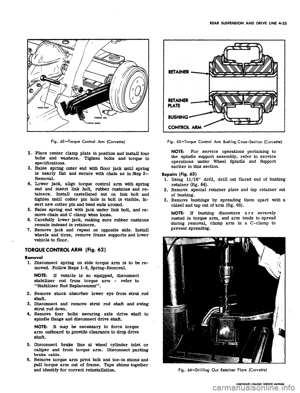
Fig.
62—Torque Control Arm (Corvette)
2.
Place center clamp plate in position and install four
bolts and washers. Tighten bolts and torque to
specifications.
3.
Raise spring outer end with floor jack until spring
is nearly flat and secure with chain as in Step 3-
Removal.
.4.
Lower jack, align torque control arm with spring
end and insert link bolt, rubber cushions and re-
tainers. Install castellated nut on link bolt and
tighten until cotter pin hole in bolt is visible. In-
sert new cotter pin and bend ends around.
5. Raise spring end with jack under link bolt, and re-
move chain and C clamp when loose.
6. Carefully lower jack, making sure rubber cushions
remain indexed in retainers.
7. Remove jack and repeat on opposite side. Install
wheels and tires, remove frame supports and lower
vehicle to floor.
TORQUE CONTROL ARM (Fig. 62)
Removal
1.
Disconnect spring on side torque arm is to be re-
moved. Follow Steps 1-6, Spring-Removal.
NOTE:
If vehicle is so equipped, disconnect
stabilizer rod from torque arm - refer to
"Stabilizer Rod Replacement".
2.
Remove shock absorber lower eye from strut rod
shaft.
3.
Disconnect and remove strut rod shaft and swing
strut rod down.
4.
Remove four bolts securing axle drive shaft to
spindle flange and disconnect drive shaft.
NOTE:
It may be necessary to force torque
arm outboard to provide clearance to drop drive
shaft.
5. Disconnect brake line at wheel cylinder inlet or
caliper and from torque arm. Disconnect parking
brake cable.
6. Remove torque arm pivot bolt and toe-in shims and
pull torque arm out of frame. Tape shims together
and identify for correct reinstallation.
RETAINER
RETAINER
PLATE
BUSHING
CONTROL ARM
Fig.
63—Torque Control Arm Bushing Cross-Sect ion (Corvette)
NOTE:
For service operations pertaining to
the spindle support assembly, refer to service
operations under Wheel Spindle and Support
earlier in this section.
Repairs (Fig. 63)
1.
Using 11/16" drill, drill out flared end of bushing
retainer (fig. 64).
2.
Remove special retainer plate and tap retainer out
of bushing.
3.
Remove bushings by spreading them apart with a
chisel and tap out of arm (fig. 65).
NOTE:
If bushing diameters are severely
rusted in torque arm, and arm tends to spread
during removal, clamp arm in a C-clamp to
prevent spreading.
Fig.
64—Drilling Out Retainer Flare (Corvette)
CHEVROLET CHASSIS SERVICE MANUAL