wheel bolts CHEVROLET CAMARO 1967 1.G Chassis Repair Manual
[x] Cancel search | Manufacturer: CHEVROLET, Model Year: 1967, Model line: CAMARO, Model: CHEVROLET CAMARO 1967 1.GPages: 659, PDF Size: 114.24 MB
Page 391 of 659
CLUTCH AND TRANSMISSIONS 7-32
21.
Remove transmission output shaft slip yoke and in-
sert a plastic shipping plug in end of extension to
prevent spillage of transmission fluid.
NOTE:
The yoke is removed to avoid tearing
the heat reflecting pad on the underbbdy, when
the transmission is being removed.
22.
Remove bright metal ignition shielding from dis-
tributor area.
23.
Remove the transmission dip stick and tube
assembly.
24.
Disconnect transmission vacuum modulator line at
distributor advance line tee.
25.
Position transmission hoist under transmission and
attach safety chain to transmission.
26.
Remove transmission converter housing-to-engine
attaching foolts and slide transmission rearward.
NOTE:
Observe converter when moving trans-
mission rearward. If converter does not move
with the transmission, pry it free of flywheel
before proceeding.
27.
Install converter retaining strap.
28.
Lower and remove transmission from vehicle by
tilting the front down and to the right while inter-
mittently lowering the transmission to facilitate its
• removal.
29.
Reinstall transmission assembly by performing the
above steps in reverse order.
Bolt Torques
Transmission Case to Flywheel
Housing Bolts 35 ft. lbs.
Converter to Flywheel Bolts. . , . . 35 ft. lbs.
OTHER SERVICE OPERATIONS
Although certain operations, such as oil pan or gasket
replacement, valve body, governor, filler pipe "O" ring,
speedometer drive gear, case extension "0" ring and
rear oil seal, vacuum modulator, and servo cover or
gasket service may be performed from underneath the
vehicle without removing the Powerglide; their service
procedure is covered in the Passenger Overhaul Manual
and is not repeated here. Refer to the- Powerglide Sec-
tion of the Passenger Overhaul Manual for all other
service operations not covered here.
DIAGNOSIS
Proper operation of the Powerglide transmission may
be affected by a number of factors, all of which must be
considered when trouble in the unit is diagnosed.
Proper trouble diagnosis can only be accomplished
when performed in a thorough step by step procedure.
The following procedure has been devised and tested and
is recommended for all trouble diagnosis complaints and
if the service man will follow this checking procedure,
accurate and dependable diagnosis may be accomplished.
This will result in a savings of time, not only to the
service man, but to the customer as well.
WARMING UP TRANSMISSION
Before attempting to check and/or correct any com-
plaints on the Powerglide transmission it is absolutely
essential that the oil level be checked and corrected if
necessary. An oil level which is either too high or too
low can be the cause of a number of abnormal conditions
from excessive noise to slippage in all ranges.
It must be remembered that cold oil will slow up the
action of the hydraulic controls in the transmission. For
this reason a trouble or oil leak diagnosis should not be
attempted until the transmission has been warmed up by
either of the following procedures:
Shop Warm Up
1.
Connect tachometer to engine.
2.
Set parking brake tight and start engine.
3.
Place selector light in
"D"
(drive) range.
4.
Adjust carburetor idle speed adjusting screw to run
engine at approximately 750 rpm and operate in this
manner for two minutes. At the end of two minutes
of operation, the transmission will be sufficiently
warmed up for diagnosis purposes.
NOTE:
At this point, readjust the engine idle
speed to 450-475 rpm in
"D"
range.
Road Warm Up
Drive the car approximately 5 miles with frequent
starts and stops.
NOTE:
At this point, make sure the engine idle
speed is set to 450-475 rpm in
"D"
range.
CHECKING FLUID LEVEL AND CONDITION
After transmission has been warmed up, check the
fluid level with the engine idling, parking brake set and
control lever in "N" (neutral). If the fluid level is low,
add fluid to bring level up to the full mark on gauge rod,
CAUTION: If fluid level is too high, fluid may
be aerated by the planet carrier. Aerated fluid
will cause turbulence in the converter which will
result in lost power, lower stall speed and lower
pressures in control circuits. Lower fluid level
to full mark, then shut off engine to allow air
bubbles to work out of fluid.
When checking oil level, aburned smell and discolora-
tion indicate burned clutches or bands and the transmis-
sion will have to be removed.
MANUAL LINKAGE
Manual linkage adjustment and the associated neutral
safety switch are important from a safety standpoint.
The neutral safety switch should be adjusted so that the
engine will start in the Park and Neutral positions only.
With the selector lever in the Park position, the park-
ing pawl should freely engage and prevent the vehicle
CHEVROLET CHASSIS SERVICE MANUAL
Page 399 of 659
CLUTCH AND TRANSMISSIONS 7-40
pipes.
If
care
is
taken
in
removing control valve
body
the six (6)
check balls will stay
in
place above
the spacer plate.
CAUTION:
Do not
drop manual valve.
5. Remove
the
governor pipes
and
manual valve from
control valve body.
Installation
Installation
of the
control valve body
is the
reverse
of
the removal.
GOVERNOR
Removal
.
1.
Remove governor cover attaching screws, cover,
and
gasket.
2.
Discard gasket.
3.
Withdraw governor assembly from case.
Installation
Installation
of the
governor assembly
is the
reverse
of
the removal.
Use a new
gasket under
the
governor
cover.
MODULATOR AND MODULATOR VALVE
Removal
1.
Remove modulator assembly attaching screw
and
retainer.
2.
Remove modulator assembly from case. Discard
"O"
ring seal.
3.
Remove modulator valve from case.
Installation
Installation
of the
modulator assembly
and
modulator
valve
is the
reverse
of the
removal.
Use a new
"O" ring
seal
on the
modulator assembly.
PARKING LINKAGE
Removal
1.
Remove bottom
pan and oil
strainer.
2.
Unthread
jam nut
holding detent lever
to
manual
shaft.
3.
Remove manual shaft retaining
pin
from case.
4.
Remove manual shaft
and jam nut
from case.
NOTE:
DO NOT
remove manual shaft seal
un-
less replacement
is
required.
5. Remove parking actuator
rod and
detent lever
as-
sembly.
6. Remove parking pawl bracket attaching screws
and
bracket.
7. Remove parking pawl return spring.
NOTE:
The
following steps should
not be com-
pleted unless part replacement
is
required.
8. Remove parking pawl shaft retainer.
9.
Remove parking pawl shaft,
cup
plug, parking pawl
shaft, and parking pawl.
Installation
Installation
of the
parking linkage
is the
reverse
of the
removal.
Use new
seal
and cup
plug,
if
removed,
and
new bottom
pan
gasket.
REAR SEAL
Removal
1.
Remove propeller shaft.
2.
Pry
seal
out
with screw driver.
Installation
1.
Using Tool J-5154
or
J-21359 install
new
seal.
2.
Re-install propeller shaft.
OTHER SERVICE WITH TRANSMISSION IN VEHICLE
The following operations when done
as
single opera-
tions
and not as
part
of a
general overhaul should,
as a
practical matter,
be
performed with
the
transmission
in
the.
vehicle. Refer
to the
"Transmission Disassembly
and Reassembly" section
of the
Overhaul Manual
for
service procedures.
a. Oil
filler pipe
and
"O"
ring seal.
b.
Oil pan
and
gasket.
c. Down shift solenoid
or
connector.
d. Valve body spacer plate, gasket
and
check balls.
e. Front accumulator piston.
f.
Rear servo
and
rear accumulator assembly.
g.
Rear band apply checking with Tool J-21370.
Ji.
Front servo assembly.
i. Speedo driven gear.
j.
Case extension
or
gasket.
k.
Strainer
and
"O"
ring.
TRANSMISSION REPLACEMENT
Before raising
the car,
disconnect
the
battery
and re-
lease
the
parking brake.
1.
Remove propeller shaft.
8.
2.
Disconnect speedometer cable, electrical lead to case
9.
connector, vacuum line
at
modulator,
and oil
cooler
10.
pipes.
3.
Disconnect shift control linkage.
4.
Support transmission with suitable transmission jack.
11.
5. Disconnect rear mount from frame crossmember.
6. Remove
two
bolts
at
each
end of
frame crossmember
12.
and remove crossmember.
7. Remove
oil
cooler lines, vacuum modulator line,
speedo cable,
and
detent solenoid connector wire
at
transmission.
Remove converter under
pan.
Remove converter
to
flywheel bolts.
Loosen exhaust pipe
to
manifold bolts approximately
1/4
inch,
and
lower transmission until jack
is
barely
supporting
it.
Remove transmission
to
engine mounting bolts
and
remove
oil
filler tube
at
transmission.
Raise transmission
to its
normal position, support
engine with jack
and
slide transmission rearward
from engine
and
lower
it
away from vehicle.
CHEVROLET CHASSIS SERVICE MANUAL
Page 442 of 659

STEERING 9-2
Fig.
1—Cover
Attaching Bolts—Chevy li Shown
ADJUSTMENTS
STEERING
GEAR
Before any adjustments are made to the steering gear
in an attempt to correct such conditions as shimmy,
loose or hard steering etc., a careful check should be
made of front end alignment, shock absorbers, wheel
balance and tire pressure for possible cause.
Correct adjustment of the steering gear is very im-
portant. Perform adjustments following the sequence
listed below,
1.
Remove pitman arm nut and mark relation of pitman
arm position to sector shaft. Remove pitman arm
with Tool J- 6632 as shown in Figure 2.
2.
Loosen the pitman shaft lash adjuster screw locknut
and turn the adjuster screw a few turns in a counter-
clockwise direction (fig. 3). This removes the load
Fig. 2—Removing Pitman Arm
imposed on the worm bearings by the close meshing
of rack and sector teeth. Turn steering wheel gently
in one direction until stopped by gear, then back away
about one turn.
CAUTION: Do not turn steering wheel hard
against stops when steering relay rod is discon-
nected as damage to ball guides may result.
3.
All except Corvette and telescopic columns:
a. Disconnect steering column harness at chassis
wiring connector plug.
b.
Remove horn cap or ornament and using an inch
pound torque wrench and socket on steering wheel
nut, measure torque required to keep the wheel
in motion.
LASH ADJUSTER
SCREW
LOCK NUT
WORM BEARING
ADJUSTER
\
WORM
ADJUSTER
Fig.
3—Steering Gear Adjustment Points
CHEVROLET CHASSIS SERVICE MANUAL
Page 443 of 659
STEERING 9-3
Fig.
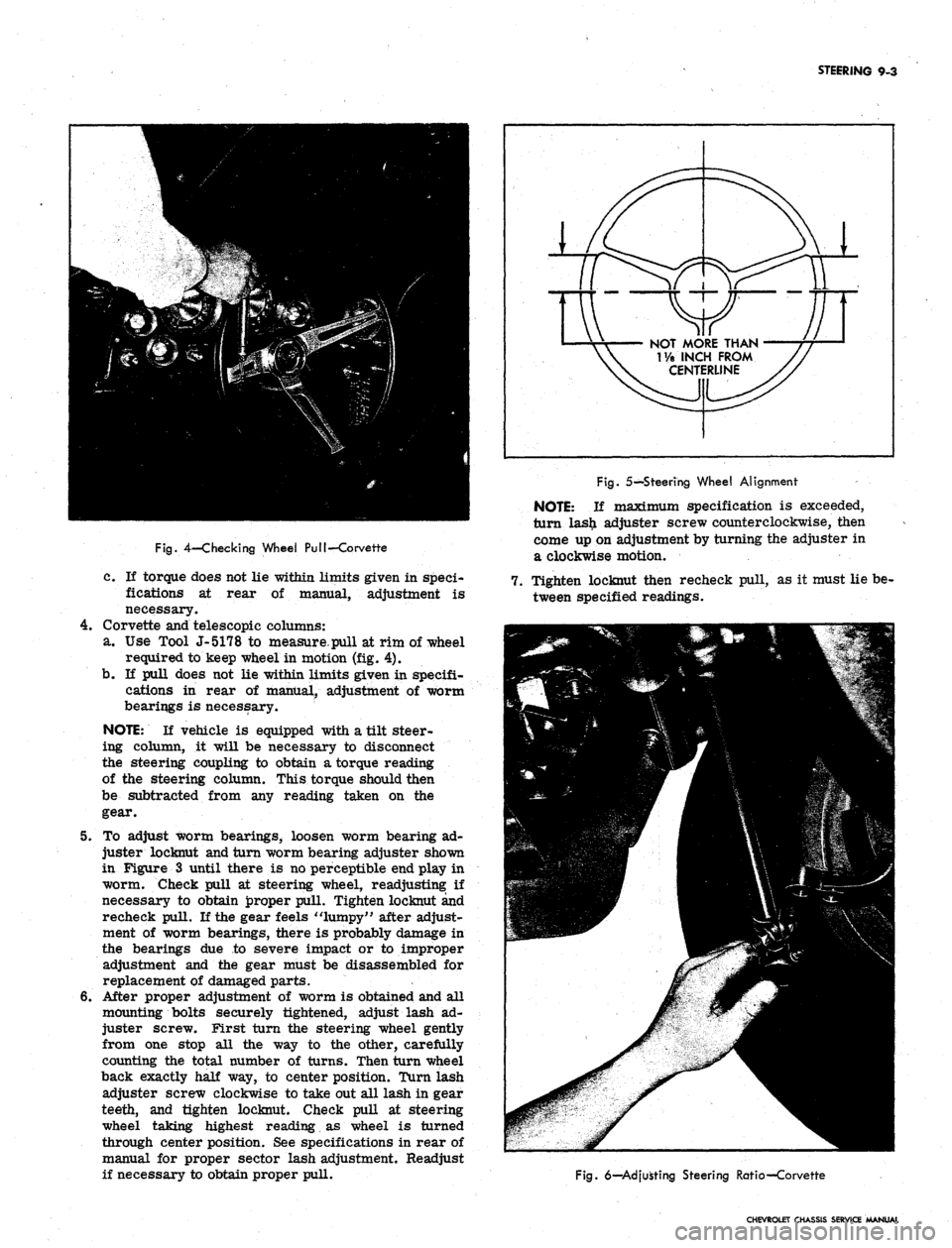
4-Checking Wheel PuI!-Corvette
c. If torque does not lie within limits given in speci-
fications at rear of manual, adjustment is
necessary.
4.
Corvette and telescopic columns:
a. Use Tool J-5178 to measure.pull at rim of wheel
required to keep wheel in motion (fig. 4).
b.
If pull does not lie within limits given in specifi-
cations in rear of manual, adjustment of worm
bearings is necessary.
NOTE:
If vehicle is equipped with a tilt steer-
ing column, it will be necessary to disconnect
the steering coupling to obtain a torque reading
of the steering column. This torque should then
be subtracted from any reading taken on the
gear.
5. To adjust worm bearings, loosen worm bearing ad-
juster locknut and turn worm bearing adjuster shown
in Figure 3 until there is no perceptible end play in
worm. Check pull at steering wheel, readjusting: if
necessary to obtain proper pull. Tighten locknut and
recheck pull. If the gear feels "lumpy" after adjust-
ment of worm bearings, there is probably damage in
the bearings due to severe impact or to improper
adjustment and the gear must be disassembled for
replacement of damaged parts.
6. After proper adjustment of worm is obtained and all
mounting bolts securely tightened, adjust lash ad-
juster screw. First turn the steering wheel gently
from one stop all the way to the other, carefully
counting the total number of turns. Then turn wheel
back exactly half way, to center position. Turn lash
adjuster screw clockwise to take out all lash in gear
teeth, and tighten locknut. Check pull at steering
wheel taking highest reading as wheel is turned
through center position. See specifications in rear of
manual for proper sector lash adjustment. Readjust
if necessary to obtain proper pull.
NOT MORE THAN
T/a INCH FROM
CENTERLINE
Fig.
5—Steering Wheel Alignment
NOTE:
If maximum specification is exceeded,
turn las£ adjuster screw counterclockwise, then
come up on adjustment by turning the adjuster in
a clockwise motion.
7. Tighten locknut then recheck pull, as it must lie be-
tween specified readings.
Fig.
6—Adjusting Steering Ratio—Corvette
CHEVROLET CHASSIS SERVICE MANUAL
Page 444 of 659
STEERING 9-4
8. Reassemble pitman arm to sector shaft, lining up
marks made during disassembly. Refer to torque
specifications at rear of manual for correct torque
value.
9. Install horn cap or ornament and connect steering
column harness at chassis connector.
NOTE:
Chevy.n models are equipped with a
shim at the frame to steering gear mounting
bolts.
Shims may be removed or installed as
required for proper steering gear alignment.
STEERING WHEEL ALIGNMENT AND
HIGH POINT CENTERING
1.
Set front wheels in straight ahead position. This can
be checked by driving vehicle a short distance on a
flat surface to determine steering wheel position at
which vehicle follows a straight path.
2.
With front wheels set straight ahead, check position
of mark on wormshaft designating steering gear high
point. This mark should be at the top side of the shaft
at 12 o'clock position and lined up with the mark in
the coupling lower clamp.
3.
If gear has been moved off high point when setting
wheels in straight ahead position, loosen adjusting
sleeve clamps on both left and right hand tie rods,
then turn both sleeves an equal number of turns in
the same direction to bring gear back on high point.
CAUTION: Turning the sleeves an unequal
number of turns or in differential directions will
disturb the toe-in setting of the wheels.
4.
Readjust toe-in as outlined in Section 3 (if necessary).
5. With wheels in a straight ahead position and the
steering gear on highpoint, check the steering wheel
alignment by measuring the distance from each hori-
zontal spoke to the horizontal centerline of the
steering wheel (fig. 5). If the horizontal spokes are
over 1-1/8 inches from the horizontal position the
wheel should be removed and centered. (See steering
wheel removal in this section.)
TOE-IN ADJUSTMENT
Adjust the steering linkage for proper toe-in setting as
outlined in Section 3.
CORVETTE STEERING RATIO (Fig. 6)
The Corvette steering ratio may be changed as follows:
CAUTION: Do not use the rearward hole in the
steering arm with power steering equipment or
interference may result.
1.
Remove tie rod ball stud nut at steering arm and
disconnect tie rod from steering arm.
2.
Move tie rod end to forward hole for 17.6:1 ratio
(fast ratio) or rear hole for 20.2:1 ratio (standard
ratio).
3.
Install tie rod stud nut and tighten securely. Repeat
operation on opposite steering arm.
COMPONENT REPLACEMENT AND REPAIRS
STEERING WHEEL
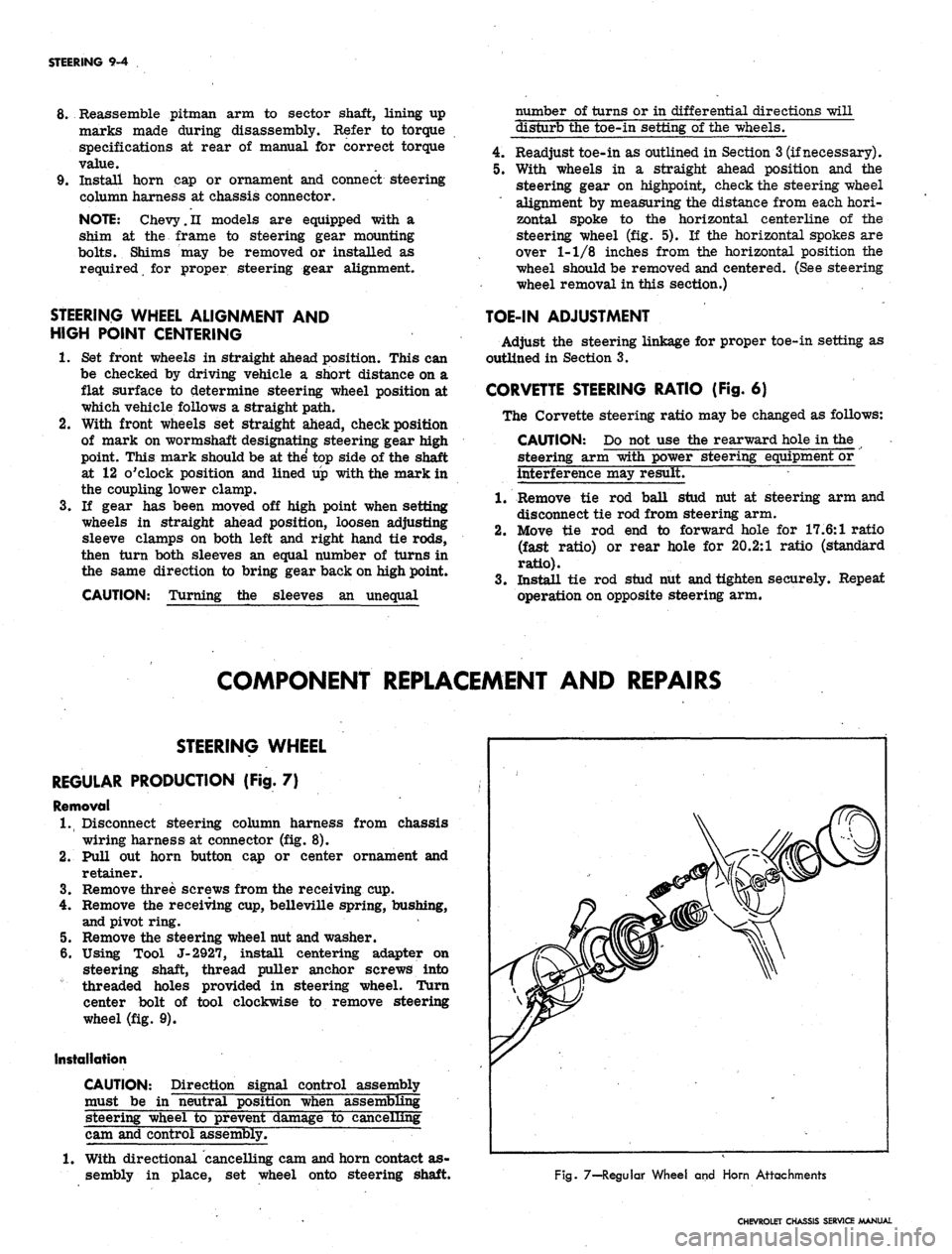
REGULAR PRODUCTION (Fig. 7)
Removal
1.
Disconnect steering column harness from chassis
wiring harness at connector (fig. 8).
2.
Pull out horn button cap or center ornament and
retainer.
3.
Remove three screws from the receiving cup.
4.
Remove the receiving cup, belleville spring, bushing,
and pivot ring.
5. Remove the steering wheel nut and washer.
6. Using Tool J-2927, install centering adapter on
steering shaft, thread puller anchor screws into
threaded holes provided in steering wheel. Turn
center bolt of tool clockwise to remove steering
wheel (fig. 9).
Installation
CAUTION: Direction signal control assembly
must be in "neutral position when assembling
steering wheel to prevent damage to cancelling
cam and control assembly.
1.
With directional cancelling cam and horn contact as-
sembly in place, set wheel onto steering shaft.
Fig. 7—-Regular Wheel and Horn Attachments
CHEVROLET CHASSIS SERVICE MANUAL
Page 452 of 659
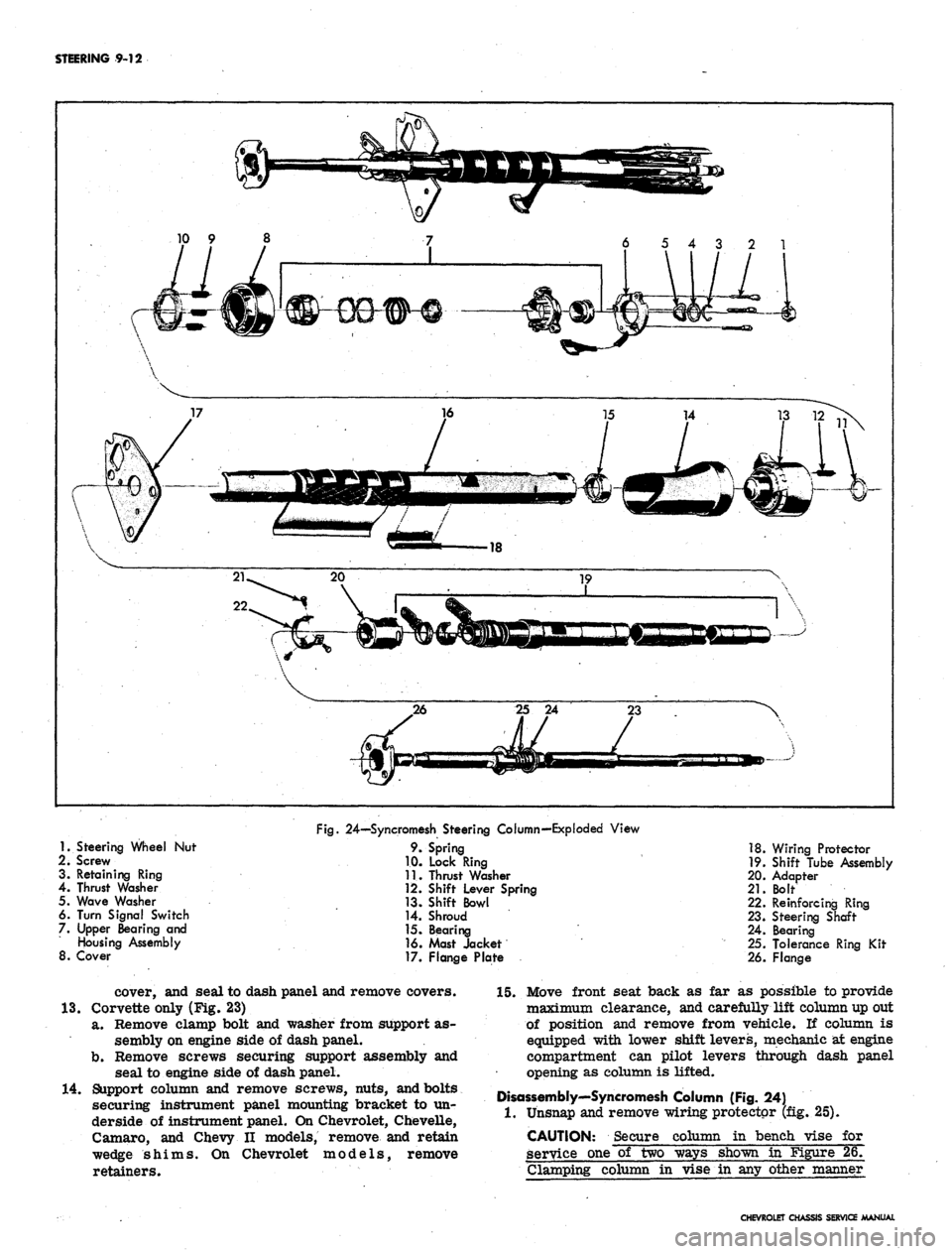
STEERING 9-12
1.
Steering Wheel Nut
2i Screw
3. Retaining Ring
4.
Thrust Washer
5. Wave Washer
6. Turn Signal Switch
7. Upper Bearing and
Housing Assembly
8. Cover
Fig.
24—Syncromesh Steering Column—Exploded View
9. Spring
1.0. Lock Ring
11.
Thrust Washer
12.
Shift Lever Spring
13.
Shift Bowl
14.
Shroud
15.
Bearing
16.
Mast Jacket
17.
Flange Plate
18.
Wiring Protector
19.
Shift Tube Assembly
20.
Adapter
21.
Bolt
22.
Reinforcing Ring
23.
Steering Shaft
24.
Bearing
25.
Tolerance Ring Kit
26.
Flange
cover, and seal to dash panel and remove covers.
13.
Corvette only (Fig. 23)
a. Remove clamp bolt and washer from support as-
sembly on engine side of dash panel.
b.
Remove screws securing support assembly and
seal to engine side of dash panel.
14.
Support column and remove screws, nuts, and bolts
securing instrument panel mounting bracket to un-
derside of instrument panel. On Chevrolet, Chevelle,
Camaro, and Chevy II models, remove and retain
wedge shims. On Chevrolet models, remove
retainers.
15.
Move front seat back as far as possible to provide
maximum clearance, and carefully lift column up out
of position and remove from vehicle. If column is
equipped with lower shift levers, mechanic at engine
compartment can pilot levers through dash panel
opening as column is lifted.
Disassembly'—Syncromesh Column (Fig. 24)
1.
Unsnap and remove wiring protector (fig. 25).
CAUTION: Secure column in bench vise for
service one of two ways shown in Figure 26.
Clamping column in vise in any other manner
CHEVROLET CHASSIS SERVICE MANUAL
Page 455 of 659
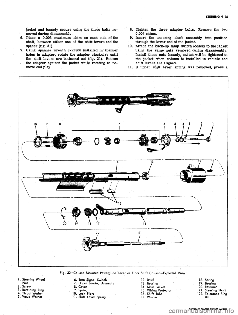
STEERING 9-15
jacket and loosely secure using the three bolts re- 8.
moved during disassembly.
Place a 0.005 maximum shim on each side of the 9.
shaft, between either one of the shift levers and the
spacer (fig. 31). 10.
Using spanner wrench J-22568 installed in spanner
holes in adapter, rotate the.adapter clockwise until
the shift levers are bottomed out (fig. 31). Bottom
the adapter against the jacket while rotating to re-
move end play. 11.
Tighten the three adapter bolts. Remove the two
0.005 shims.
Insert the steering shaft assembly into position
through the lower end of the jacket.
Attach the back-up lamp switch loosely to the jacket
using the same nuts removed during disassembly.
Install these nuts loosely, switch will be tightened to
the jacket when column is installed in vehicle and
shift levers are aligned.
If upper shift lever spring was removed, press a
10 9 8
6 5 4 3 2 1
Fig.
32—Column Mounted Powerglide Lever or Floor Shift Column—Exploded View
1.
Steering Wheel
Nut
2.
Screw
3. Retaining Ring
4.
Thrust Washer
5. Wave Washer
6. Turn Signal Switch
7. Upper Bearing Assembly
8. Cover
9. Spring
10.
Lock Plate
11.
Shift Lever Spring
12.
Bowl
13.
Bearing
14.
Mast Jacket
15.
Wiring Protector
16.
Shift Tube
17.
Washer
18.
Spring
19.
Bearing
20.
Retainer
21.
Steering Shaft
22.
Tolerance Ring
Kit
CHEVROLET CHASSIS SERVICE MANUAL
Page 464 of 659
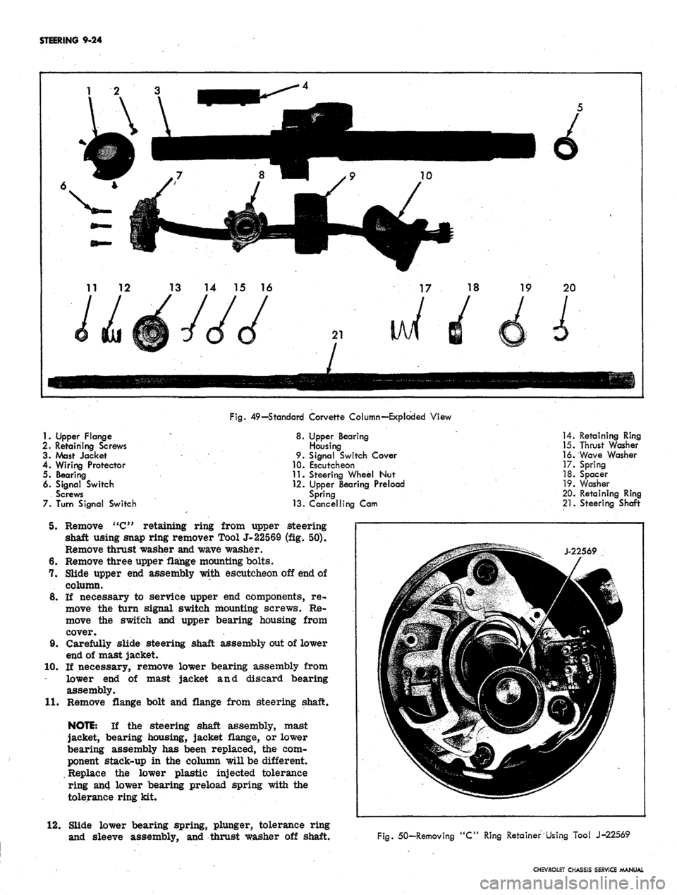
STEERING
9-24
1.
Upper Flange
2.
Retaining Screws
3.
Mast Jacket
4.
Wiring Protector
5. Bearing
6. Signal Switch
. Screws
7.
Turn Signal Switch
Fig.
49—Standard Corvette Column—Exploded View
8.
Upper Bearing
Housing
9.
Signal Switch Cover
10.
Escutcheon
11.
Steering Wheel Nut
12.
Upper Bearing Preload
Spring
13.
Cancelling Cam
5. Remove "C" retaining ring from upper steering
shaft using snap ring remover Tool J-22569 (fig. 50).
Remove thrust washer and wave washer.
6. Remove three upper flange mounting bolts.
7. Slide upper end assembly with escutcheon off end of
column.
8. If necessary to service upper end components, re-
move the turn signal switch mounting screws. Re-
move the switch and upper bearing housing from
cover.
9. Carefully slide steering shaft assembly out of lower
end of mast jacket.
10.
If necessary, remove lower bearing assembly from
lower end of mast jacket and discard bearing
assembly.
11.
Remove flange bolt and flange from steering shaft.
NOTE:
If the steering shaft assembly, mast
jacket, bearing housing, jacket flange, or lower
bearing assembly has been replaced, the com-
ponent stack-up in the column will be different.
Replace the lower plastic injected tolerance
ring an4 lower bearing preload spring with the
tolerance ring kit.
12.
Slide lower bearing spring, plunger, tolerance ring
and sleeve assembly, and thrust washer off shaft.
14.
Retaining Ring
15.
Thrust Washer
16.
Wave Washer
17.
Spring
18.
Spacer
19.
Washer
20.
Retaining Ring
21.
Steering Shaft
Fig.
50-Removing "C" Ring Retainer Using Tool J-22569
CHEVROLET CHASSIS SERVICE MANUAL
Page 469 of 659

STEERING 9-29
column mounting bracket, and place bracket in cor-
rect position on underside of instrument panel.
Loosely install bracket using bracket to column
mounting screws and bracket to instrument panel
washers and bolts.
NOTE: Steering shaft to gear clamp must be
tightened before column attaching bolts are
torqued. Refer to "Steering Gear-Chevy n",
installation procedure, for correct Chevy II
steering column alignment procedure.
5.
Camaro only (fig. 60):
Lay wedge shim in position on instrument panel
column mounting bracket and place bracket in cor-
rect position on underside of instrument panel.
Loosely install bracket using bracket to column
mounting screws, nuts, and washer and bolt as shown
in Figure 60.
6. Corvette only (fig. 61):
Loosely secure column mounting bracket to sup-
port plate and instrument panel with washers and
bolts.
7.
Secure flanged end of column to steering coupling
with lockwashers and nuts. On Chevy n, connect col-
umn to steering gear with clamp, clamp bolt, and
nut. On Corvette, slide steering shaft flange into
lower coupling
half,
and install upper clamp bolt
loosely; also secure support, seal and clamp loosely
at dash on engine side.
8. Tighten instrument panel mounting bracket bolts and
nuts.
Refer to torque specifications at rear of manual
for correct torque values.
9. Chevrolet only (fig. 15):
Place upper and lower mast jacket covers in po-
sition and secure covers together and to instrument
panel using nuts and screws as shown in Figure 15.
10.
Chevy H only (fig. 18):
Place lower mast jacket cover in position under
mast jacket and secure to upper cover with screws.
11.
CheveUe only (fig. 15):
Place mast jacket trim cover in position over col-
Fig.
61—Instrument Panel Mounting Bracket and
Support Plqte—Corvette
umn on underside of instrument panel and secure
with screws.
12.
Corvette only (fig. 14):
Slide escutcheon into position at instrument panel
and secure with screws. Place upper end lower
covers in position and secure with screws.
13.
On Chevrolet and CheveUe models with column
mounted powerglide controls, secure transmission
shift indicator pointer into position with set screw
(fig. 15). ,
14.
Chevrolet only (fig. 19):
a. Secure seal and cover to dash panel with screws.
b.
Place clamp assembly in position and install
clamp screw.
c. Install dash panel trim cover with mounting
screws.
15.
Chevelle only (fig. 20):
a. Secure seal and inner and outer covers to dash
panel with screws.
b.
Secure inner and outer covers together with
screws.
c. Install trim cover to dash panel with two
retainers.
16.
Chevy H only (fig. 21):
a. Secure seal, retainer, and clamp to dash panel
with screws.
b.
Install clamp screw.
c. Slide collar into position. Pinch and staple upper
tabs together.
17.
Camaro only (fig. 22):
a. Secure seal, upper cover, and lower cover to
dash panel with screws.
b.
Secure upper and lower cover together with
screws.
c. Fold rubber boot over securely against dash panel
to conceal covers.
18.
Corvette only (fig. 23):
a. Secure seal and support assembly to dash panel
on engine compartment side.
b.
Tighten clamp, washer, and clamp bolt on engine
compartment side.
19.
Connect transmission linkage to lower shift tube
levers in engine compartment, if column is so
equipped. Adjust levers as outlined in Section 7.
20.
Install steering wheel as outlined in this section.
21.
Connect directional signal, horn, back-up lamp, and
neutral start switch at wiring harness plugs. Adjust
back-up lamp, neutral start switch as outlined in
Section 12.
22.
Adjust steering gear and align and center steering
wheel as outlined in this section.
STEERING LINKAGE (Fig. 62)
TIE RODS
There are two tie rod assemblies used on all models.
Each assembly is of three piece construction, consisting
of a sleeve and two tie rod ends. The ends are threaded
into the sleeve and locked with clamps. Right and left
hand threads are provided to facilitate toe-in adjustment
and steering gear centering.
The tie rod ends are self-adjusting for wear and re-
quire no attention in service other than periodic lubrica-
tion and occasional inspection to see that ball studs are
tight. Replacement of tie rod ends should be made when
CHEVROLET CHASSIS SERVICE MANUAL
Page 471 of 659

STEERING 9-31
Fig.
63—Freeing Ball Stud
rod threads with EP Chassis lube and install ends on
tie rod making sure both ends are threaded ah equal
distance from the tie rod.
2.
Make sure that threads on ball stud and in ball stud
nuts are perfectly clean and smooth. Install neoprene
seals on ball studs.
NOTE: If threads are not clean and smooth,
ball studs may turn in tie rod ends when at-
tempting to tighten nut.
3.
Install ball studs in steering arms and relay rod.
4.
Install ball stud nut, and install cotter pins. Lubri-
cate tie rod ends.
5.
Adjust toe-in as described in Section 3.
NOTE: Before locking clamp bolts on the rods,
make sure that the tie rod ends are in alignment
with their ball studs (each ball joint is in the
center of its travel). If the tie rod is not in
alignment with the studs, binding will result.
RELAY ROD-ALL MODELS EXCEPT CORVETTE
Removal
1.
Remove inner ends of tie rods from relay rod as
described under Tie Rod - Removal.
2.
Remove cotter pin and nut from relay rod ball stud
attachment at pitman arm.
3.
Detach relay rod from pitman arm. Shift steering
linkage as required to free pitman arm from relay
rod.
4.
Remove cotter pin and nut from idler arm and re-
move relay rod from idler arm.
Installation
1.
Install relay rod to idler arm, making certain idler
stud seal is in place, then install and tighten nut.
Advance nut just enough to align castellation with
cotter pin hole and install pin.
2.
Raise end of rod and install on pitman arm. Secure
with nut and cotter pin.
3.
Install tie rod ends to relay rod as previously
described under Tie Rods. Lubricate tie rod ends.
4.
Adjust toe-in (see Section 3) and align steering wheel
as described previously in this section under Steer-
ing Wheel Alignment and High Point Centering.
RELAY ROD-CORVETTE
Removal
1.
Remove steering damper from relay rod as outlined
under Steering Damper-Removal. Remove anchor
bracket from relay rod by disconnecting two mount-
ing bolts.
2.
Remove inner ends of tie rods from relay rod as
described under Tie Rod--Removal.
3.
Remove cotter pin from end of relay rod at pitman
arm ball stud attachment, and remove stud nut.
4.
Tap brJl stud out of pitman arm and lower relay rod.
5.
Remove cotter key and nut from idler arm and re-
move relay rod from idler arm. Remove washer and
seal from idler arm.
Installation
1.
Place relay rod on idler arm stud, making certain
idler stud seal and washer are in place, then install
and tighten nut. Advance nut just enough to align
castellation with cotter pin hole and install pin.
2.
Install new seal and clamp over ball at end of pitman
arm.
3.
Install inner spring seat and spring to relay rod.
4.
Raise end of rod and install on pitman arm.
5.
Install spring seat, spring, and end plug.
6. Tighten end plug until springs are compressed and
plug bottoms, then back off 3/4 turn plug amount
necessary to insert cotter pin. Insert cotter pin to
lock adjustment.
7.
Install tie rod ends to relay rod as previously de-
scribed under Tie Rods.
8. Lubricate tie rod ends and pitman arm to relay rod
ball joint.
9. Install steering damper bracket and tighten bolts.
Install damper as outlined under Steering Damper--
Installation.
10.
Adjust toe-in and align steering wheel as described
previously in this section.
IDLER ARM
Chevrolet, Chevelle, Comoro, and Corvette (Fig. 62)
Removal
1.
Remove idler arm to frame nut, washer, and bolt.
No washer is used on Corvette.
2.
Remove cotter pin and nut from idler arm to relay
rod ball stud.
3.
Remove relay rod from idler arm by tapping relay
rod with a hammer using a heavy hammer as a
backing.
4.
Remove idler arm.
Installation
1.
On Chevrolet, place seal in position on idler arm
stud; position stud up through frame, and secure with
lock washer and nut.
2.
On Chevelle, Camaro, and Corvette, position idler
CHEVROLET CHASSIS SERVICE MANUAL